Showing 93 items
matching distance measures
-
 Eltham District Historical Society Inc
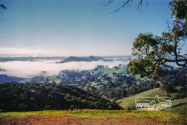
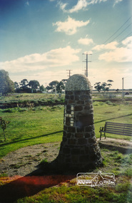
Photograph, Murchison Gap viewed from Strath Creek, Autumn Excursion, Hume and Hovell's 1824 expedition, 26 May 1996, 26/05/1996
... of the You Yangs to Lara and Avalon Beach. Because their distance... of the You Yangs to Lara and Avalon Beach. Because their distance ...[article by Bettina Woodburn in EDHS Newsletter No. 109, July 1996:] ON THE TRAIL OF HUME AND HOVELL - REPORT ON THE AUTUMN EXCURSION - On a green and fresh morning (Sunday 26th May 1996) the Cobb and Co coach (driven by the most obliging Peter Tampion) set off in a north easterly direction from Eltham to connect with Hume and Hovell's route on their 1824 explorations of central Victoria. The Society would follow a series of monuments erected for the 1924 centenary of the expedition from King Parrot Creek (Tuesday 7th December 1824), through Strath Creek, over Sunday Creek (Sunday 12th December 1824) at Broadford, Tullamarine, St Albans, Deer Park, through Werribee, skirting east of the You Yangs to Lara and Avalon Beach. Because their distance-measuring wheel had broken and a one degree mistake was made in calculations, the two leaders of the original group of six convict-companions arrived at Corio Bay, instead of the expected Western Port, discovered earlier by Flinders. From below Mt. Disappointment (Hume and Hovell's difficulties in "scrambling over brush and rock", "leeches in forest, as well as no water", "cutting grass 4-5 ft. high", dreadful scrub", "devil flies") we took an easier route, saw the Strath Creek memorial in ground fog and a wonderful "field of dreams", the Hume-Hovell privately owned cricket ground with its white picket boundary fence. Now, after a steep climb, in sunshine under gums we stretched and viewed magnificent rolling hills and fog-filled valleys - not "smoke from Aborigines' bush fires". After morning tea at Broadford we followed the Sunday Creek valley beside the Hume Freeway, passed the Wallan Wallan Rest Area (more appropriately Hume and Hovell Rest Area) to tum right at Beveridge. In Gellibrand Hill Park, near the headwaters of the Moonee Ponds Creek, we experienced the landscape the first European settlers saw - huge river red gums and rolling pastures. The gardens and sheltered courtyard of the 1840s, timber, brought from .....[?] prefabricated Woodlands Homestead, provided a pleasant lunch stop. We enjoyed a private tour, panoramic views over Melbourne and surroundings and the excitement of arriving and departing aircraft. Our next river crossing was at Werribee, "in a vast treeless plain", then we drove on by-ways no coach had previously travelled, to find "an immense sheet of water" salty Corio Bay, off-course to the west. In late afternoon of a super, calm, late autumn day we headed homewards. Back at Eltham we were rather surprised to find that we had travelled a total of 347 km. Thanks again to Russell Yeoman for his research and organization. What a wonderful day! Colour photographactivities, hume and hovell, murchison valley, murchison gap, strath creek -
 Eltham District Historical Society Inc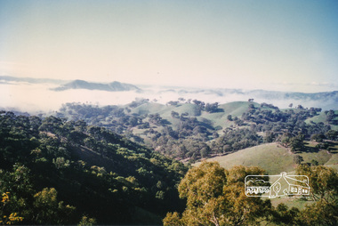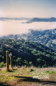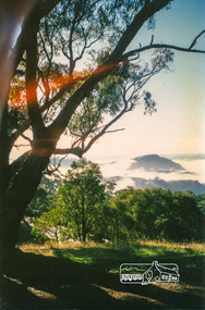
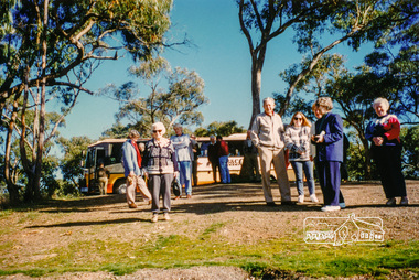
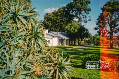
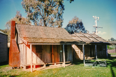
Photograph, Autumn Excursion, Hume and Hovell's 1824 expedition, 26 May 1996, 26/05/1996
... of the You Yangs to Lara and Avalon Beach. Because their distance... of the You Yangs to Lara and Avalon Beach. Because their distance ...[article by Bettina Woodburn in EDHS Newsletter No. 109, July 1996:] ON THE TRAIL OF HUME AND HOVELL - REPORT ON THE AUTUMN EXCURSION - On a green and fresh morning (Sunday 26th May 1996) the Cobb and Co coach (driven by the most obliging Peter Tampion) set off in a north easterly direction from Eltham to connect with Hume and Hovell's route on their 1824 explorations of central Victoria. The Society would follow a series of monuments erected for the 1924 centenary of the expedition from King Parrot Creek (Tuesday 7th December 1824), through Strath Creek, over Sunday Creek (Sunday 12th December 1824) at Broadford, Tullamarine, St Albans, Deer Park, through Werribee, skirting east of the You Yangs to Lara and Avalon Beach. Because their distance-measuring wheel had broken and a one degree mistake was made in calculations, the two leaders of the original group of six convict-companions arrived at Corio Bay, instead of the expected Western Port, discovered earlier by Flinders. From below Mt. Disappointment (Hume and Hovell's difficulties in "scrambling over brush and rock", "leeches in forest, as well as no water", "cutting grass 4-5 ft. high", dreadful scrub", "devil flies") we took an easier route, saw the Strath Creek memorial in ground fog and a wonderful "field of dreams", the Hume-Hovell privately owned cricket ground with its white picket boundary fence. Now, after a steep climb, in sunshine under gums we stretched and viewed magnificent rolling hills and fog-filled valleys - not "smoke from Aborigines' bush fires". After morning tea at Broadford we followed the Sunday Creek valley beside the Hume Freeway, passed the Wallan Wallan Rest Area (more appropriately Hume and Hovell Rest Area) to tum right at Beveridge. In Gellibrand Hill Park, near the headwaters of the Moonee Ponds Creek, we experienced the landscape the first European settlers saw - huge river red gums and rolling pastures. The gardens and sheltered courtyard of the 1840s, timber, brought from .....[?] prefabricated Woodlands Homestead, provided a pleasant lunch stop. We enjoyed a private tour, panoramic views over Melbourne and surroundings and the excitement of arriving and departing aircraft. Our next river crossing was at Werribee, "in a vast treeless plain", then we drove on by-ways no coach had previously travelled, to find "an immense sheet of water" salty Corio Bay, off-course to the west. In late afternoon of a super, calm, late autumn day we headed homewards. Back at Eltham we were rather surprised to find that we had travelled a total of 347 km. Thanks again to Russell Yeoman for his research and organization. What a wonderful day! Colour photographactivities, hume and hovell -
 Eltham District Historical Society Inc
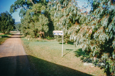
Photograph, Sign to Hume and Hovell Cricket Ground, at Allandale Road, Strath Creek, Autumn Excursion, Hume and Hovell's 1824 expedition, 26 May 1996, 26/05/1996
... of the You Yangs to Lara and Avalon Beach. Because their distance... of the You Yangs to Lara and Avalon Beach. Because their distance ...[article by Bettina Woodburn in EDHS Newsletter No. 109, July 1996:] ON THE TRAIL OF HUME AND HOVELL - REPORT ON THE AUTUMN EXCURSION - On a green and fresh morning (Sunday 26th May 1996) the Cobb and Co coach (driven by the most obliging Peter Tampion) set off in a north easterly direction from Eltham to connect with Hume and Hovell's route on their 1824 explorations of central Victoria. The Society would follow a series of monuments erected for the 1924 centenary of the expedition from King Parrot Creek (Tuesday 7th December 1824), through Strath Creek, over Sunday Creek (Sunday 12th December 1824) at Broadford, Tullamarine, St Albans, Deer Park, through Werribee, skirting east of the You Yangs to Lara and Avalon Beach. Because their distance-measuring wheel had broken and a one degree mistake was made in calculations, the two leaders of the original group of six convict-companions arrived at Corio Bay, instead of the expected Western Port, discovered earlier by Flinders. From below Mt. Disappointment (Hume and Hovell's difficulties in "scrambling over brush and rock", "leeches in forest, as well as no water", "cutting grass 4-5 ft. high", dreadful scrub", "devil flies") we took an easier route, saw the Strath Creek memorial in ground fog and a wonderful "field of dreams", the Hume-Hovell privately owned cricket ground with its white picket boundary fence. Now, after a steep climb, in sunshine under gums we stretched and viewed magnificent rolling hills and fog-filled valleys - not "smoke from Aborigines' bush fires". After morning tea at Broadford we followed the Sunday Creek valley beside the Hume Freeway, passed the Wallan Wallan Rest Area (more appropriately Hume and Hovell Rest Area) to tum right at Beveridge. In Gellibrand Hill Park, near the headwaters of the Moonee Ponds Creek, we experienced the landscape the first European settlers saw - huge river red gums and rolling pastures. The gardens and sheltered courtyard of the 1840s, timber, brought from .....[?] prefabricated Woodlands Homestead, provided a pleasant lunch stop. We enjoyed a private tour, panoramic views over Melbourne and surroundings and the excitement of arriving and departing aircraft. Our next river crossing was at Werribee, "in a vast treeless plain", then we drove on by-ways no coach had previously travelled, to find "an immense sheet of water" salty Corio Bay, off-course to the west. In late afternoon of a super, calm, late autumn day we headed homewards. Back at Eltham we were rather surprised to find that we had travelled a total of 347 km. Thanks again to Russell Yeoman for his research and organization. What a wonderful day! Colour photographactivities, hume and hovell, allandale road, strath creek -
 Eltham District Historical Society Inc
Photograph, Autumn Excursion, Hume and Hovell's 1824 expedition, 26 May 1996, 26/05/1996
... of the You Yangs to Lara and Avalon Beach. Because their distance... of the You Yangs to Lara and Avalon Beach. Because their distance ...[article by Bettina Woodburn in EDHS Newsletter No. 109, July 1996:] ON THE TRAIL OF HUME AND HOVELL - REPORT ON THE AUTUMN EXCURSION - On a green and fresh morning (Sunday 26th May 1996) the Cobb and Co coach (driven by the most obliging Peter Tampion) set off in a north easterly direction from Eltham to connect with Hume and Hovell's route on their 1824 explorations of central Victoria. The Society would follow a series of monuments erected for the 1924 centenary of the expedition from King Parrot Creek (Tuesday 7th December 1824), through Strath Creek, over Sunday Creek (Sunday 12th December 1824) at Broadford, Tullamarine, St Albans, Deer Park, through Werribee, skirting east of the You Yangs to Lara and Avalon Beach. Because their distance-measuring wheel had broken and a one degree mistake was made in calculations, the two leaders of the original group of six convict-companions arrived at Corio Bay, instead of the expected Western Port, discovered earlier by Flinders. From below Mt. Disappointment (Hume and Hovell's difficulties in "scrambling over brush and rock", "leeches in forest, as well as no water", "cutting grass 4-5 ft. high", dreadful scrub", "devil flies") we took an easier route, saw the Strath Creek memorial in ground fog and a wonderful "field of dreams", the Hume-Hovell privately owned cricket ground with its white picket boundary fence. Now, after a steep climb, in sunshine under gums we stretched and viewed magnificent rolling hills and fog-filled valleys - not "smoke from Aborigines' bush fires". After morning tea at Broadford we followed the Sunday Creek valley beside the Hume Freeway, passed the Wallan Wallan Rest Area (more appropriately Hume and Hovell Rest Area) to tum right at Beveridge. In Gellibrand Hill Park, near the headwaters of the Moonee Ponds Creek, we experienced the landscape the first European settlers saw - huge river red gums and rolling pastures. The gardens and sheltered courtyard of the 1840s, timber, brought from .....[?] prefabricated Woodlands Homestead, provided a pleasant lunch stop. We enjoyed a private tour, panoramic views over Melbourne and surroundings and the excitement of arriving and departing aircraft. Our next river crossing was at Werribee, "in a vast treeless plain", then we drove on by-ways no coach had previously travelled, to find "an immense sheet of water" salty Corio Bay, off-course to the west. In late afternoon of a super, calm, late autumn day we headed homewards. Back at Eltham we were rather surprised to find that we had travelled a total of 347 km. Thanks again to Russell Yeoman for his research and organization. What a wonderful day! Colour photographactivities, hume and hovell -
 Eltham District Historical Society Inc
Photograph, Autumn Excursion, Hume and Hovell's 1824 expedition, 26 May 1996, 26/05/1996
... of the You Yangs to Lara and Avalon Beach. Because their distance... of the You Yangs to Lara and Avalon Beach. Because their distance ...[article by Bettina Woodburn in EDHS Newsletter No. 109, July 1996:] ON THE TRAIL OF HUME AND HOVELL - REPORT ON THE AUTUMN EXCURSION - On a green and fresh morning (Sunday 26th May 1996) the Cobb and Co coach (driven by the most obliging Peter Tampion) set off in a north easterly direction from Eltham to connect with Hume and Hovell's route on their 1824 explorations of central Victoria. The Society would follow a series of monuments erected for the 1924 centenary of the expedition from King Parrot Creek (Tuesday 7th December 1824), through Strath Creek, over Sunday Creek (Sunday 12th December 1824) at Broadford, Tullamarine, St Albans, Deer Park, through Werribee, skirting east of the You Yangs to Lara and Avalon Beach. Because their distance-measuring wheel had broken and a one degree mistake was made in calculations, the two leaders of the original group of six convict-companions arrived at Corio Bay, instead of the expected Western Port, discovered earlier by Flinders. From below Mt. Disappointment (Hume and Hovell's difficulties in "scrambling over brush and rock", "leeches in forest, as well as no water", "cutting grass 4-5 ft. high", dreadful scrub", "devil flies") we took an easier route, saw the Strath Creek memorial in ground fog and a wonderful "field of dreams", the Hume-Hovell privately owned cricket ground with its white picket boundary fence. Now, after a steep climb, in sunshine under gums we stretched and viewed magnificent rolling hills and fog-filled valleys - not "smoke from Aborigines' bush fires". After morning tea at Broadford we followed the Sunday Creek valley beside the Hume Freeway, passed the Wallan Wallan Rest Area (more appropriately Hume and Hovell Rest Area) to tum right at Beveridge. In Gellibrand Hill Park, near the headwaters of the Moonee Ponds Creek, we experienced the landscape the first European settlers saw - huge river red gums and rolling pastures. The gardens and sheltered courtyard of the 1840s, timber, brought from .....[?] prefabricated Woodlands Homestead, provided a pleasant lunch stop. We enjoyed a private tour, panoramic views over Melbourne and surroundings and the excitement of arriving and departing aircraft. Our next river crossing was at Werribee, "in a vast treeless plain", then we drove on by-ways no coach had previously travelled, to find "an immense sheet of water" salty Corio Bay, off-course to the west. In late afternoon of a super, calm, late autumn day we headed homewards. Back at Eltham we were rather surprised to find that we had travelled a total of 347 km. Thanks again to Russell Yeoman for his research and organization. What a wonderful day! Colour photographactivities, hume and hovell -
 Bendigo Military Museum
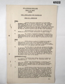
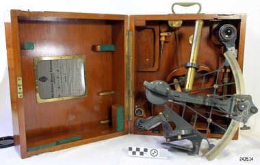
Administrative record - Royal Australian Survey Corps - 1st, 2nd and 3rd Order Triangulation Precis, School of Military Survey, Balcombe, Circa 1948 - 1960
... by measuring only angles to it from known points at either end... by measuring only angles to it from known points at either end ...A School of Military Survey Precis, 8 x foolscap sized pages of typed text, stapled and two hole punched. The precis No 3 covers the Observation procedure to be used for 1st, 2nd and 3rd Order Triangulation using the Royal Australian Survey Corps standard Cooke, Troughton and Simms Tavistock or Wild T2. The geodetic model Tavistock with a 5.25" horizontal circle should be used for 1st Order Triangulation and maybe used for 2nd Order Triangulation if specially directed. The standard Tavistock with 3.5" horizontal circle or the Wild T2 should be used for 2nd and 3rd Order observations. The Precis discusses the types of errors, the source of errors and the best ways of managing them. In surveying, triangulation is the process of determining the location of a point by measuring only angles to it from known points at either end of a fixed baseline by using trigonometry, rather than measuring distances to the point directly as in trilateration.A School of Military Survey Precis, 8 x foolscap sized pages of typed text, stapled and two hole punched.royal australian survey corps, rasvy, fortuna, army survey regiment, army svy regt, asr, school of military survey, sms, balcombe -
 Flagstaff Hill Maritime Museum and Village
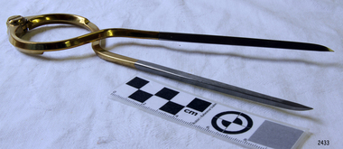
Functional object - Map Calipers/ Divider, Unknown
... adjustment. Or the marine dividers used to measure the distance... dividers used to measure the distance a vessel has travelled ...Compass, divider, and caliper are basically instruments that have two legs pivoted to each other at the top and are concerned with small-distance measurement or transfer. The compass and divider have straight legs; the caliper has curved legs. Dividers and Calipers were known to both the Greeks and Romans, though the caliper was uncommon. A divider with a circular sector, or wing, connecting the two legs was sketched in 1245, its modern counterpart is the wing divider with a thumbscrew clamp and screw for fine adjustment. Or the marine dividers used to measure the distance a vessel has travelled by transferring the vessels distance from a map with the divider and transferring that measurement to a marine ruler to mathematical calculate the distance.Item is believed to be a replica/ copy of a 19th century map calipers used in marine navigation to determine distance travelled. Item was probably purchased between 1972-1975 to add to the marine displays at Flagstaff Hill.Stainless steel dividers used in navigation charts. Top half is alloy plated. "W & HC" and "Made in England".flagstaff hill, warrnambool, shipwrecked-coast, flagstaff-hill, flagstaff-hill-maritime-museum, maritime-museum, shipwreck-coast, flagstaff-hill-maritime-village, stainless steel dividers, steel dividers, dividers -
 Flagstaff Hill Maritime Museum and Village
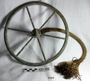
Tool - Ship Taffrail Log Flywheel, 1930+
... of the rotor would register on the indicator, thus measuring... on the indicator, thus measuring the distance the vessel had travelled ...The flywheel possibly belongs to a Walker's Cherub Mark III Ship-log taffrail, how the flywheel operates is a metal loop of the recording log would have been connected to the flywheel, so you could see if it was spinning properly. After the flywheel, is the rotor that was towed behind the ship and the revolutions of the rotor would register on the indicator, thus measuring the distance the vessel had travelled. Thomas Ferdinand Walker (1837–1921) first patented the Cherub log in 1878. It was one of the first logs in which the recorder was placed onboard a ship rather than being incorporated as part of the rotor. The Cherub Mark III series was produced from 1930 it came in two versions a thousand-mile which is quite rare and a five hundred-mile version.This ship log flywheel was invented and made by a significant marine instrument maker and innovator of machinery Thomas Walker. It demonstrates the huge leap taken to improve navigational accuracy at sea with an instrument that was in use for decades to measure the distance travelled at sea updated versions are in use today by mariners.Log Governor (or Fly-wheel) from a Ships Taffrail Log, metal wheel with 6 spokes, hub has rope attached for connecting to ships log. Boss the other side for attachment to the spinner.Noneflagstaff hill, warrnambool, shipwrecked-coast, flagstaff-hill, flagstaff-hill-maritime-museum, maritime-museum, shipwreck-coast, flagstaff-hill-maritime-village, log governor -
 Flagstaff Hill Maritime Museum and Village
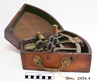
Instrument - Navigational Sextant, 1882-1890
... latitude and longitude at sea by measuring angular distances... mainly by sailors to measure the angular distance between two ...A sextant is an astronomical instrument used to determine latitude and longitude at sea by measuring angular distances, especially the altitudes of the sun, moon, and stars. It is a doubly reflecting navigation instrument and used mainly by sailors to measure the angular distance between two visible objects. The name comes from the Latin sextans, or “sixth part of a unit,” because the sextant’s arc can be 60° or 120° of a circle depending on the model used. The primary use was to measure the angle between an astronomical object and the horizon for the purposes of celestial navigation. The estimation of this angle is known as sighting or shooting the object, or taking a sight. This angle and the time when it was measured is used in order to determine Greenwich Mean Time and hence longitude. Sighting the height of a landmark on land can also give a measure of distance from that object. History: The development of the sextant was as an improvement over the octant, an instrument designed to measure one's latitude. The octant was first implemented around 1731-present but can only measure angles up to 45°. As larger angles were needed to allow the measurement of lunar objects - moon, stars and the sun - at higher angles, the octant was superseded by the sextant. The sextant is a similar instrument but better made and allows larger angles from 60° to 120°. This improvement allows distances to be accurately calculated thereby giving longitude when used with a chronometer. The sextant was derived from the octant in 1757, eventually making all previous instruments used for navigational positioning obsolete. The sextant had been attributed to by John Hadley (1682–1744) and Thomas Godfrey (1704–1749), but reference to the sextant was also found later in the unpublished writings of Isaac Newton (1643–1727). Earlier links can be found to Bartholomew Gosnold (1571–1607) indicating that the use of a sextant for nautical navigation predates Hadley's implementation. In 1922, the sextant was modified for aeronautical navigation by Portuguese navigator and naval officer Gago Coutinho. It should be noted that the octant and quadrant are in the same family as they were, and all are, regarded as sextants. The sextant is representative of it's type and although not fully complete it demonstrates how 18th,19th and 20th century mariners determined their latitude and longitudinal to determine their position on a chart, allowing them to navigate there way across the world's oceans. It also demonstrates the skill and workmanship of the early instrument makers that operated scientific instrument businesses from London and other areas of England to provide most of the navigational instrumentation used by commercial and military navies of the time.Sextant with square, fitted box of polished wood, "Hezzanith" brand. Box contains many parts for the sextants use. On certificate "Heath & Co, London. Sextant Number Y 822". Catch on lid "DEFIANT LEVER" and "PATENT NUMBER 187.10". Maker's certificate is attached to the inside of the box.flagstaff hill, warrnambool, shipwrecked-coast, flagstaff-hill, flagstaff-hill-maritime-museum, maritime-museum, shipwreck-coast, flagstaff-hill-maritime-village, sextant box, sextant, hezzanith, heath & co, navigational instrument, george wilson heath, astronomical instrument, instrument manufacturers, scientific instrument, navigation, celestial navigation, octant, quadrant, lunar navigation -
 Myrtleford and District Historical Society
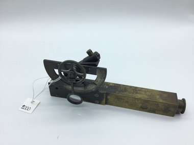
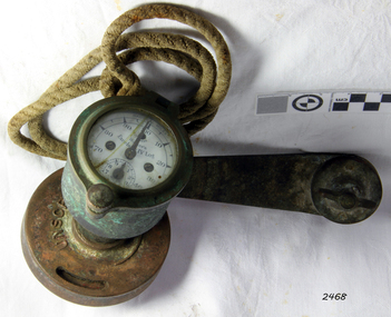
Inclinometer, Early 20th Century
... and by measuring the distance on the ground to the object, trigonometry can... of the subject object. An angle is thus obtained and by measuring ...Provenance not clear. Leather case has 'MMBW' inscribed in black pen, indicating an association with Melbourne Metropolitan Board of Works. Item has been in the possession of Terry McCormack since 1972Hand held brass pocket inclonometer level, circa 1920. Leather case for safe storage. Semi circular graduated dial with 90 degree vernier scale with a small (20mm) magnifying glass to aid reading the vernier scale. Above the body, mounted at the rear of the graduated dial, is a spirit level tube which is tilted by finger movement to the milled hand wheel. The height to be determined is sighted through the instrument eyepiece and the bubble tube is tilted until the bubble, viewed in the mirror inside the sighting tube, is brought level with the graticule sighted at the top of the subject object. An angle is thus obtained and by measuring the distance on the ground to the object, trigonometry can be applied to determine the height of the object.Herga & Co. BRISBANE. Made in England -
 Bendigo Military Museum
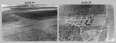
Photograph - RA Svy Project C4 Aerodist Operation, Eastern Arnhem Land, NT, 1967
... adapted for aircraft to accurately measure distances between non... adapted for aircraft to accurately measure distances between non ...This is a set of 30 photographs of Royal Australian Survey Corps (RA Svy) personnel from Central Comd Fd Svy Unit (Adelaide) on Aerodist survey operation - Project C4 in Eastern Arnhem Land, Northern Territory in 1967. Photos of personnel were taken either at the operations base at Numbulwar or the main base at Gove (Nhulunbuy). RA Svy conducted nineteen Aerodist operations for 12 years from 1964 to 1975. Aerodist MRC2 was a tellurometer-based system adapted for aircraft to accurately measure distances between non-intervisible ground survey stations, using the aircraft as an intermediate station. Lower order geodetic results could be achieved by survey network trilateration. The measured distances between stations formed survey networks from which each station’s latitude and longitude was computed. Aerodist MRC2 was RA Svy’s major horizontal control survey tool for mainly medium scale topographic mapping (scale 1:100,000 Class A being spatially accurate to within 50 metres) in PNG, northern NT, north-west WA, Kalimantan Barat (West) Indonesia, Sumatra Indonesia, Gulf of Carpentaria and Cape York, QLD. In 1967, the Aerodist MRC2 Master equipment was installed in the aircraft featured in this set of photos, Executive Air Services’ (Essendon VIC) Grand Aero Commander VH-EXX. It was the same aircraft type and company contracted to Division of National Mapping for Aerodist MRC2 surveys. From July to October 1967 the aircraft was attached to Central Comd Fd Svy Unit (Adelaide - Major Don Ridge) on Project C4 eastern-Arnhem Land NT, where 317 Aerodist lines measuring 17,300 line miles were successfully completed. This was the most productive Aerodist project thus far. The most common helicopter used by RA Svy up to 1972 was the civilian Bell 47G-2 and the Sioux Light Observation Helicopters (LOH), the Australian Army’s equivalent featured in this photo set. These light observation helicopters had a limiting load carrying capacity of up to about 500 pounds. By comparison, one Aerodist team including two people weighed up to 1,500 pounds. Source: Royal Australian Survey Corps – Aerodist Years 1964-1975 by Peter Jensen. This is a set of 30 photographs of Royal Australian Survey Corps (RA Svy) personnel on Aerodist survey operations in Eastern Arnhem Land, Northern Territory in 1967. The photographs are on 35mm negative film and scanned at 96 dpi. They are part of the Army Survey Regiment’s Collection. .1) to .4) - black & white, 20th August 1967, Project C4 Aerodist Operations Base - Numbulwar, NT. .5) - Photo, black & white, 1967. Probable wrecked Indonesian fishing vessel. .6) to .8) - Photo, black & white, 1967. Unidentified survey operations base, L to R: unidentified personnel. .9) - Photo, black & white, 1967. Unidentified survey operations base, unidentified soldier driving a Haflinger 4x4 Light utility vehicle. .10) - Photo, black & white, 1967. Unidentified survey operations base, L to R: unidentified technician. .11) - Unidentified technician reading two survey altimeters to compute corrections to the measured distances for atmospheric refraction and to compute the sea level distances from the slope distances aircraft to the ground stations. .12) - Photo, black & white, 1967. Unidentified survey operations base, L to R: unidentified personnel. .13) to .16) - Photo, black & white, 1967. Unidentified personnel operating remote Aerodist MRC2 ground instruments. .17) to .18) - Photo, black & white, 1967. Unknown RA Svy office location. .19) to .20) - Photo, black & white, 1967. Aerodist MRC2 Master equipment. .21) to .22) - Photo, black & white, 1967. Aero Commander VH-EXX probably at Gove, NT, Central Comd Fd Svy Unit (Adelaide) – OC Major Don Ridge. .23) to .25) - Photo, black & white, 1967. Aero Commander VH-EXX probably at Gove, NT. Unidentified personnel. .26) - Photo, black & white, 1967. Aero Commander VH-EXX probably at Gove, NT. Aerodist antenna pods are visible on the aircraft. .27) to .29) - Photo, black & white, 1967. Australian Army Sioux Light Observation Helicopter (LOH) probably at Gove, NT. .30) - Photo, black & white, 1967. Panelled U337 survey station, visible as a white cross on aerial identification photo..1P to .2P – date and location on edge of film negative. .5P to .28P – no annotations .29P - annotated in white ‘RW-JEP Gove NT’ .30P - annotated in white ‘U337 Spool No1 Jun67’royal australian survey corps, rasvy, army survey regiment, army svy regt, fortuna, asr, aerodist, surveying, central comd fd svy unit -
 Flagstaff Hill Maritime Museum and Village
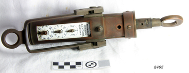
Ship Log, 1900-1920
... the distance traveled. The counter could measure enough miles to cover... the ship over a fixed time period in order to measure the distance ...Thomas Walker & Son was internationally renowned in the manufacturing of ships logs. Founding father Thomas Walker (1805–1871), an engineer in Birmingham, patented a mechanical log in 1878 which was a recording instrument that attached to a rail at the stern of a vessel connected by a long cord with a rotor which was towed behind the ship. The instrument dial recorded the distance travelled. Thomas Walker first went into business to manufacture stoves at 58 Oxford Street Birmingham. Walker’s self-feeding stove was widely lauded at the Paris Exhibition of 1855, winning a prize medal and kick starting the first of many notable innovations for the Walker family's manufacturing business. However, it wasn’t until working on an earlier ships log model invented by his Uncle that Thomas Walker became interested in the further development of this device, used to ascertain a ship’s speed. Walker continued to improve on the common log for the company of Massey & Sons and these improvements were deemed revolutionary. This log became a firm favourite of the West India Association (British-based organisation promoting ties and trade with the British Caribbean) and the most common log in use for two generations. It took till 1861 for Thomas Walker and his son, Thomas Ferdinand Walker (1831-1921) to patent the first Walker log of many. Together, with the introduction of the A1 Harpoon Log two years later, they established the Walker Log Business as a force to be reckoned with. By the time of his passing in 1871, Thomas Walker Snr had not only founded a family business with considerable staying power but also instilled a tradition of public service. Having sat as a representative on the Birmingham Town Council for 15 years and played an active role in public works, he was soon given the nickname of ‘Blue Brick Walker’. Much like his father, Thomas Ferdinand Walker changed the face of the maritime industry. His patent of 1897, the ‘Cherub’ log, was a notable departure from the past providing a far more accurate reading and replacing the majority of logs of the age. They were the first to produce an electric log and the Walker factory was one of the first to introduce the 48 hour work week for employees. This ship log was invented and made by a significant marine instrument maker and innovator of machinery. It demonstrates the huge leap taken to improve navigational accuracy at sea with an instrument that was in use for decades. Ship Log, three analogue dials calibrated in increments of Miles, the Rocket Log is a nautical instrument for measuring a vessel’s speed and distance traveled. The floating log was drawn behind the ship over a fixed time period in order to measure the distance traveled. The counter could measure enough miles to cover the maximum distance traveled by a ship in one day. The log has two distinct parts; a brass register, made by Walker, showing the distance recorded and the rotator made by Reynolds, that spins in the water driving the counter. both parts are connected by a linked chain. The register has a cylindrical brass body approx 4.5 cm diameter containing registering mechanism with hardened steel bearings. Distance is indicated by the three pointers on enamel plate as follows: graduated every 10 miles from 0-100; every mile from 1-10; every 1/4 mile from 1/4 -1. A brass sling and eye secured to the body enables it to be attached to the taffrail. The original rotator would have had a cylindrical tapered wooden body, approx 4.5 cm in diameter with three metal alloy fins or could be all made from brass. A towing eye is fitted to the tapered end. The two pieces of apparatus are connected by a length of linked chain, length 22.9 cm."Walkers Rocket Ship-Log Birmingham (Patented)" printed on face-plate. "Made by Thomas Walker".flagstaff hill, warrnambool, shipwrecked-coast, flagstaff-hill, flagstaff-hill-maritime-museum, maritime-museum, shipwreck-coast, flagstaff-hill-maritime-village, ship log, rocket log, mechanical ship log, measuring instrument, marine instrument, nautical instrument, speed recording instrument, ship log register, walker ship log, walkers rocket ship-log, thomas walker, thomas walker & son, thomas ferdinand walker, walker log business, reynolds ship log rotor, taffrail log, taff rail log, west india association -
 Flagstaff Hill Maritime Museum and Village
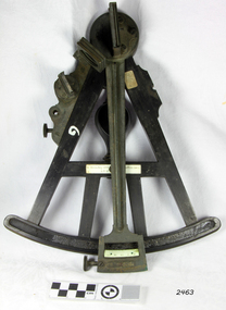
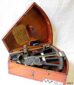
Octant, Late 18th to mid-19th century
... primarily by sailors to measure the angular distance between two... navigation instrument used primarily by sailors to measure ...An Octant is a doubly reflecting navigation instrument used primarily by sailors to measure the angular distance between two visible objects and was a forerunner of the sextant. The name comes from the Latin octo, or “one-eighth of a circle,” for the Octant’s arc which spans 45°, or one-eighth of a circle. The primary use of an Octant is to measure the angle between an astronomical object and the horizon for the purposes of celestial navigation. The estimation of this angle is known as sighting or shooting the object, or taking a sight. The angle, and the time when it was measured, can be used to calculate a position line on a nautical chart (latitude), for example, sighting the Sun at noon or Polaris at night (in the Northern Hemisphere) gives an angle by which the latitude can then be estimated. Sighting the height of a landmark on land can also give a measure of distance. History: The principle of the Octant as an instrument to measure ones latitude was first implemented around 1742-present but was superseded by the improvement of the octant to a sextant, a very similar instrument, better made and able to measure bigger angles 120°, allowing the measurement of Luna distances to give longitude when used with an accurate chronometer. The sextant started to appear around 1730 and had been attributed to by John Hadley (1682–1744) and Thomas Godfrey (1704–1749), but reference to the sextant was also found later in the unpublished writings of Isaac Newton (1643–1727). Earlier links can be found to Bartholomew Gosnold (1571–1607) indicating that the use of a Sextant for nautical navigation predates Hadley's implementation. In 1922, the sextant was modified for aeronautical navigation by Portuguese navigator and naval officer Gago Coutinho. Henry Hemsley was a lesser-known instrument maker and optician working in London in the late 17th and early 18th century. However, it should be noted that there were two Henry Hemsley opticians and instrument makers around this period. (Henry Hemsley 1, 1786-89, who had premises at 85 Fleet St London and Henry Hemsley 2, 1828-56), whose workshop was at 135-138 Radcliff Highway London. Therefore, based on the inscribed workshop address Henry Hemsley 2 is responsible for making this example.The octant is representative of its type and although not fully complete it demonstrates how 18th and 19th-century mariners determined their latitude on a chart to navigate their way across the world's oceans in the 18th and 19th century. It also demonstrates the skill and workmanship of the early instrument makers that operated from London at this time and provided most of the navigational instrumentation use by commercial and military navies of the time.Octant, ebony wooden frame and handle. Scale is missing from recess in frame. "H. Hemsley 135-138 Ratliff Highway, London", no box"H. Hemsley 135-138 Ratcliff Highway, London"flagstaff hill, warrnambool, shipwrecked-coast, flagstaff-hill, flagstaff-hill-maritime-museum, maritime-museum, shipwreck-coast, flagstaff-hill-maritime-village, navigation, navigational instrument, instrument used for navigation, sextant, henry hemsley, instrument maker, london, octant -
 Flagstaff Hill Maritime Museum and Village
Instrument - Octant, mid 1800's
... primarily by sailors to measure the angular distance between two... of a landmark on land can also give a measure of distance. This fine ...An Octant is a doubly reflecting navigation instrument used primarily by sailors to measure the angular distance between two visible objects and was a forerunner of the sextant. The name comes from the Latin octo, or "one-eighth of a circle," for the Octan'ts arc which spans 45°, or one-eighth of a circle. The primary use of an Octant is to measure the angle between an astronomical object and the horizon for celestial navigation. The estimation of this angle, is known as sighting or shooting the object, or taking a sight. The angle, and the time when it was measured, can be used to calculate a position line on a nautical chart (latitude), for example, sighting the Sun at noon or Polaris at night (in the Northern Hemisphere) gives an angle by which the latitude can then be estimated. Sighting the height of a landmark on land can also give a measure of distance. This fine octant once belonged to Captain Farquhar Chisholm and was donated by his granddaughter, Margaret Ruth Greer (nee Chisholm, born 1914). The label inside the Octant's box reads “Thomas L. Ainsley, Instrument Maker … etc”. Farquhar Chisholm was born in 1832 in Inverness, Scotland. He regularly sailed on perilous voyages between Quebec, Canada and the Baltic ports of Europe. In 1854 he migrated to Australia during the Gold Rush, to a place called Fiery Creek (near Beaufort Victoria) where he was fairly successful in his quest for gold. In the years of the Great Gold Rush, it was said that there were over 40,000 diggers in the goldfields of the Beaufort area! In 1857 having made sufficient money, he hired another crew and returned to Clachnacuddin, Inverness shire, Scotland and in that same year, he studied and obtained his Master Mariner Certificate (which would have included the use of an octant for navigation). He was appointed to Mr George (or James) Walker, as commander of his sailing ship, the 3-masted ELIZABETH, built 1859 and known as “The Walker barque”. In 1870 he married, then in 1887 returned to Australia with his wife and children (Kenneth Chisholm (1871), Mary Bremner Chisholm (1873), Margaret Hood Chisholm (1874), Farquhar Chisholm (1878)). They arrived in Port Melbourne, Victoria and sadly, only six weeks after landing, his wife Caroline passed away (in Geelong,1888). In 1900 Capt. Chisholm lived in Camperdown (Victoria) and not long after this his daughter Margaret died of consumption. In his later years, he went to live in the manse of St. Paul’s Presbyterian Church, Wangaratta, with his son, Rev. Farquhar Chisholm. He died there on Sat, 23rd March 1912, 80 years old. He was known as “… quiet, unobtrusive and competent, respected by all with whom he came in contact”. Some other members of Captain Chisholm’s family are; his older son Kenneth Chisholm, who was a contractor in Camperdown; a nephew Donald Macintosh (of 23 Douglas Row, Inverness); a grandson Brian Jones (son of Caroline Belle-Jones nee Chisholm, who lived in Camperdown in the earlier part of her life).The octant, the forerunner of the sextant, was a significant step in providing accuracy of a sailors latitude position at sea & his vessels distance from land when taking sightings of land-based landmarks.Octant, once belonging to Captain Farquhar Chisholm. Wedge shape (the size of an eighth of a circle), made of wood, glass and metal. Used in the 1880s. Maker’s name across centre “L. SIMON - - - SHIELDS”. Three (3) light filtering, coloured glass shades. Two (2) eyepieces. Scale attached for measuring angles. Label inside the fitted, wedge-shaped case "Thomas L. Ainsley, Optician"Label inside case "Thomas L. Ainsley, Optician" Maker’s name across centre “L. SIMON - - - SHIELDS”.flagstaff hill, warrnambool, shipwrecked-coast, flagstaff-hill, flagstaff-hill-maritime-museum, maritime-museum, shipwreck-coast, flagstaff-hill-maritime-village, maritime navigation, navigation instrument, migration, captain chisholm, farquhar chisholm, sailing ship, the elizabeths, thomas l. ainsley, l. simons, shields england, octant, john hadley, chisholm -
 Flagstaff Hill Maritime Museum and Village
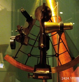
Instrument - Sextant, Late 20th Century
... . It is a doubly reflecting navigation instrument that measures the angular.... It is a doubly reflecting navigation instrument that measures the angular ...In 1941, the scientific instrument manufacturing firms of Henry Hughes & Son Ltd, London, England, and Kelvin Bottomley & Baird Ltd, Glasgow, Scotland, came together to form Kelvin & Hughes Ltd. Kelvin Company History: The origins of the company lie in the highly successful and strictly informal relationship between William Thomson (1824-1907), Professor of Natural Philosophy at Glasgow University from 1846-1899 and James White, a Glasgow optical maker. James White (1824-1884) founded the firm of James White, an optical instrument maker in Glasgow in 1850 and was involved in supplying and mending apparatus for Thomson university laboratory and working with him on experimental constructions. White was declared bankrupt in August 1861 and released several months later. In 1870, White was largely responsible for equipping William Thomson laboratory in the new University premises at Gilmore hill. From 1876, he was producing accurate compasses for metal ships to Thomson design during this period and this became an important part of his business in the last years of his life. He was also involved in the production of sophisticated-sounding machinery that Thomson had designed to address problems encountered laying cables at sea, helping to make possible the first transatlantic cable connection. At the same time, he continued to make a whole range of more conventional instruments such as telescopes, microscopes and surveying equipment. White's association with Thomson continued until he died. After his death, his business continued under the same name, being administered by Matthew Edwards (until 1891 when he left to set up his own company. Thomson who became Sir William Thomson and then Baron Kelvin of Largs in 1892, continued to maintain his interest in the business after James White's death. In 1884 raising most of the capital needed to construct and equip new workshops in Cambridge Street, Glasgow. At these premises, the company continued to make the compass Thomson had designed during the 1870s and to supply it in some quantity, especially to the Admiralty. At the same time, the firm became increasingly involved in the design, production and sale of electrical apparatus. In 1899, Lord Kelvin resigned from his University chair and became, in 1900, a director in the newly formed limited liability company Kelvin & James White Ltd which had acquired the business of James White. At the same time Kelvin's nephew, James Thomson Bottomley (1845-1926), joined the firm. In 1904, a London branch office was opened which by 1915 had become known as Kelvin, White & Hutton Ltd. Kelvin & James White Ltd underwent a further change of name in 1913, becoming Kelvin Bottomley & Baird Ltd. Hughes Company History: Henry Hughes & Sons were founded in 1838 in London as a maker of chronographic and scientific instruments. The firm was incorporated as “Henry Hughes & Sons Ltd” in 1903. In 1923, the company produced its first recording echo sounder and in 1935 a controlling interest in the company was acquired by S Smith & Son Ltd resulting in the development and production of marine and aircraft instruments. Following the London office's destruction in the Blitz of 1941, a collaboration was entered into with Kelvin, Bottomley & Baird Ltd resulting in the establishing “Marine Instruments Ltd”. Following the formal amalgamation of Kelvin, Bottomley & Baird Ltd and Henry Hughes & Sons Ltd in 1947 to form Kelvin & Hughes Ltd. Marine Instruments Ltd then acted as regional agents in the UK for Kelvin & Hughes Ltd who were essentially now a part of Smith's Industries Ltd founded in 1944 and the successors of S. Smith & Son Ltd. Kelvin & Hughes Ltd went on to develop various marine radar and echo sounders supplying the Ministry of Transport, and later the Ministry of Defence. The firm was liquidated in 1966 but the name was continued as Kelvin Hughes, a division of the Smiths Group. In 2002, Kelvin Hughes continues to produce and develop marine instruments for commercial and military. G. Falconer Company History: G Falconer (Hong Kong Ltd) appear to have had a retail presence in Hong Kong since 1885, according to the company website, and currently have a shop in the Peninsula Hotel. G Falconer was the Hong Kong selling agent for several British companies. Ross Ltd of 111 New Bond St London was one and the other was Kelvins Nautical Instruments. Falconers were primarily watchmakers, jewellers and diamond merchants.They were also agents for Admiralty Charts, Ross binoculars and telescopes, and sold English Silverware and High Class English Jewellery. In 1928 the company was operating from the Union Building opposite the Hong Kong general post office. It is unclear if the item is an original Sextant made by Kelvin prior to his amalgamation with Henry Hughes & Sons in 1941 as Kelvin appears to have only made compasses up to this date. If the Sextant can be established that it was made by Kelvin then it is very significant and a rare item made for and distributed through their Hong Kong selling agents G Falconer Ltd. There are many Sextants advertised for sale stating "Kelvin & Hughes 1917 model sextant". These can be regarded as replicas as the company was not formed until 1941 and production of marine instruments was not fully under way until after the war in 1947. Further investigation needs to be undertaken to accurately determine the provenance of this item. As the writer currently has the impression that the subject object was possibly made by Kelvin and Hughes in the mid to late 20th century or is a replica made by an unknown maker in the late 1970s. Purchased as an exhibition of marine navigational instruments for the Flagstaff Hill museum. The Sextant is a brass apparatus with filters and telescope lens, and comes with a wooden felt lined storage box. It is a doubly reflecting navigation instrument that measures the angular distance between two visible objects. The primary use of a sextant is to measure the angle between an astronomical object and the horizon for the purposes of celestial navigation.G Falconer and Co. Hong Kong (retailers of nautical equipmentflagstaff hill, warrnambool, shipwrecked-coast, flagstaff-hill, flagstaff-hill-maritime-museum, maritime-museum, shipwreck-coast, flagstaff-hill-maritime-village, sextant, kelvin & hughes ltd, hong kong, navigational instrument, g falconer, mariner's quadrants -
 Flagstaff Hill Maritime Museum and Village
Ship Log, 1900-1920
The Excelsior IV Log is a nautical instrument for measuring a vessel’s speed and distance travelled. When navigating a ship it is essential to be able to estimate the boat’s speed and distance travelled to determine its position at sea. In times past the only way to measure a ship’s speed was to throw a wood log into the water and observe how fast it moved away from the ship. In the 16th century, the log was fastened to a rope knotted at set intervals. The log was thrown over the stern (back) of the vessel and a crew member counted the number of knots that were paid out in a set time. From this, they could estimate the speed of the vessel through the water. This was known as streaming the log and is also the derivation of the knot as a measurement of nautical speed. The Walker’s Excelsior Mark IV instrument was designed for smaller vessels, such as yachts, launches and fishing vessels. Historical: Thomas Walker & Son was internationally renowned in the manufacturing of ships logs, founding father , Thomas Walker (1805–1871), an engineer in Birmingham, patented a mechanical log in 1878 which was a recording instrument that attached to a rail at the stern of a vessel connected by a long cord with a rotor which was towed behind the ship. The instrument dial recorded the distance travelled. Thomas Walker first went into business to manufacture stoves at 58 Oxford Street Birmingham. Walker’s self-feeding stove was widely lauded at the Paris Exhibition of 1855, winning a prize medal and kick starting the first of many notable innovations for the Walker family's manufacturing business. However, it wasn’t until working on an earlier ship’s log model invented by his Uncle that Thomas Walker became interested in the further development of this device, used to ascertain a ship’s speed. Walker continued to improve on the common log for the company of Massey & Sons and these improvements were deemed revolutionary. This log became a firm favourite of the West India Association (British-based organisation promoting ties and trade with the British Caribbean), being the most common log in use for two generations. It took until 1861 for Thomas Walker and his son, Thomas Ferdinand Walker (1831-1921) to patent the first Walker log of many. Together, with the introduction of the A1 Harpoon Log two years later, they established the Walker Log Business as a force to be reckoned with. By the time of his passing in 1871, Thomas Walker Snr had not only founded a family business with considerable staying power but also instilled a tradition of public service. Having sat as a representative on the Birmingham Town Council for 15 years and played an active role in public works, he was soon given the nickname of ‘Blue Brick Walker’. Much like his father, Thomas Ferdinand Walker changed the face of the maritime industry. His patent of 1897, the ‘Cherub’ log, was a notable departure from the past providing a far more accurate reading and replacing the majority of logs of the age. They were the first to produce an electric log and the Walker factory was one of the first to introduce the 48 hour work week for employees. The ship log was invented and made by a significant marine instrument maker and innovator of machinery. It demonstrates the huge leap taken to improve navigational accuracy at sea with an instrument that was in use for decades.Ship's Taff Rail Log, rope attached. Walker's Excelsior IV Log model. Nautical miles dials: units and 10's. "Walker's Excelsior IV Log", "Made in England by Thomas Walker, Birmingham"flagstaff hill, warrnambool, shipwrecked-coast, flagstaff-hill, flagstaff-hill-maritime-museum, maritime-museum, shipwreck-coast, flagstaff-hill-maritime-village, log register, taff rail log, taffrail log, marine navigation, a1 harpoon log, cherub’ log, walker’s excelsior mark iv log, ship’s log instrument, mechanical ship’s log, measure ship’s speed, nautical instrument, navigation instrument, massey & sons, thomas walker, blue brick walker, thomas walker & son, thomas ferdinand walker, 48 hour work week -
 Bendigo Military Museum
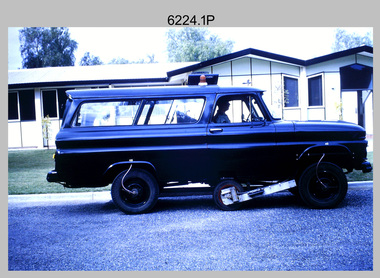
Photograph - Johnson Ground Elevation Meter (JGEM) Survey Vehicle - Army Survey Regiment, Fortuna, Bendigo, c1960s
This is a set of 16 photograph of the Royal Australian Survey Corps’ Johnson Ground Elevation Meter (JGEM) Survey Vehicle taken at the Army Survey Regiment, Fortuna, Bendigo. The JGEM vehicle was extensively used by RA Svy within Australia from the late 1960s. A limited number of Ground Elevation Meter (GEM) station wagon type vehicles were manufactured by General Motors Corporation (GMC) in the USA for the United States Geological Survey, Canada’s mapping agencies, RA Svy and National Mapping (Natmap). The GEM was a four-wheel drive, four-wheel steer vehicle. Four-wheel steering was necessary to avoid systematic errors caused by non-tracking of front and rear wheels on conventionally steered vehicles. The manufacturer substituted the rear axle with a front axle and connected them to form the four-wheel steering mechanism. The two Australian GEM vehicles, referred to as Johnson GEMs (JGEMs) were converted into right-hand drive. After delivery in 1964, acceptance Natmap and RA Svy testing and operator training was undertaken at the Army's School of Military Survey located at Balcombe, Victoria. A small fifth wheel was mounted on a cantilever arm suspension midway between the front and rear wheels on the right side of the vehicle. It was lowered to and raised from its operating position by use of a constant pressure air cylinder. A telescopic bar, suspended between the front and rear axles, provided the reference datum for the angle measurement. The wheel provided the velocity or distance signal through a pulse generator system. A sensitive pendulum mounted on this bar provided the angle measurement for each minute distance traversed. The JGEM contained electromechanical instruments used to determine relative elevations, by trigonometric principles, along a traversed path. These relative elevations were obtained through apparatus which measures the instantaneous angle of inclination of the road and the instantaneous velocity of the meter along such a path. Road routes over which the JGEM operated were planned so that each started and ended as near as practicable to an existing point of known elevation (formally referred to as a level traverse bench mark). The difference in height from the bench mark and the road surface alongside the JGEM’s fifth wheel was measured with a level and staff. Along each route, mapping control photo reference points where new elevation values were required were identified on aerial photographs. Under favourable conditions it was possible to survey as much as 160km in an ordinary working day. The first of RA Svy’s JGEM operations was undertaken in 1:250,000 scale map areas of Queensland. CPL John Hook was the JGEM’s main operator in the early 1970s undertaking operations covering 1:250,000 scale map blocks over northern Victoria and central NSW, each requiring 36 points (9 runs of photography and 4 points across. SPR Lyn Thompson and SPR Bob McDonagh teamed with CPL Hook on some of these JGEM operations. When RA Svy was integrated into the Royal Australian Engineers in 1996, the JGEM vehicle with the Survey Corps collection was donated to its museum. It is believed to be the last of the original manufactured fleet in existence. The JGEM has undergone extensive refurbishment to achieve roadworthiness and is currently housed at The Australian Army Museum of Military Engineering, Hoslworthy Barracks, NSW. It can be viewed by making an appointment with the museum’s curator.This is a set of 16 photograph of the Royal Australian Survey Corps’ Johnson Ground Elevation Meter (JGEM) Survey Vehicle taken at the Army Survey Regiment, Fortuna, Bendigo. The photographs were on 35mm slide film and were scanned at 96 dpi. They are part of the Army Survey Regiment’s Collection. .1) - Photo, colour, c1960s, Johnson Ground Elevation Meter (JGEM) Survey Vehicle .2) - Photo, colour, c1960s, JGEM instrumentation, on-board computer. .3) - Photo, colour, c1960s, JGEM instrumentation. .4) - Photo, colour, c1960s, JGEM instrumentation, on-board computer. .5) - Photo, colour, c1960s, JGEM tyre pressure controller .6) - Photo, colour, c1960s, JGEM rear doors, SGT Geoff Briggs. .7) - Photo, colour, c1960s, JGEM 5th wheel distance/angle measurement device in lowered position, SGT Geoff Briggs. .8) - Photo, colour, c1960s, JGEM 5th wheel distance/angle measurement device in lowered position. .9) & .10) - Photo, colour, c1960s, JGEM tyre pressure system, SGT Geoff Briggs. .11) - Photo, colour, c1960s, JGEM tyre pressure system. SGT Geoff Briggs. .12) - Photo, colour, c1960s, JGEM levelling scope, levelling staff, unidentified technicians. .13) & .14) - Photo, colour, c1960s, JGEM levelling scope, unidentified technician. .15) & .16) - Photo, colour, c1960s, probably survey operation adjusted height plotted on block base sheet. .1P to .16P - Some of the equipment is annotated on the frame of the 35mm slides.royal australian survey corps, rasvy, army survey regiment, army svy regt, fortuna, asr, surveying -
 Bendigo Military Museum
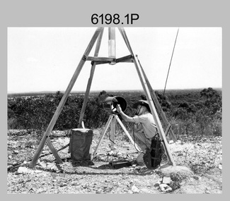
Photograph - Royal Australian Survey Corps Electronic Distance Measuring Equipment Demonstration, c1960s
... Survey Corps Electronic Distance Measuring Equipment ...This is a set of five photographs of CAPT James ‘Jim’ Leslie Stedman in the field demonstrating the setup of prisms used as electric distance measurement (EDM) receiver reflectors for tellurometer equipment and the sighting of a large surveyor’s light. This equipment was deployed in establishing mapping and geodetic control operations. The photos were most likely taken in the late 1950s or early 1960s. The tellurometers of this era were man-portable systems that improved geodetic survey efficiencies for rapid network extension and densification replacing triangulation with EDM and theodolite traverse sometimes using Bilby Towers to extend line lengths. Jim Stedman later reached the rank of Colonel, was Director of Military Survey from 1975 to 1978 and was appointed as Colonel Commandant (honorary appointment, Retd) of the Royal Australian Survey Corps from 1978 to 1983. Jim Stedman is demonstrating EDM equipment. See item 6180.16P, photos .14) to .16) for more information and photos of Jim Stedman’s EDM demonstration. This is a set of five photographs of a surveyor in the field demonstrating electric distance measurement (EDM) equipment. c1950s – 1960s. The photographs were printed on photographic paper and are part of the Army Survey Regiment’s Collection. The photographs were scanned at 300 dpi. .1) to .2) - Photo, black & white, c1960s, CAPT Jim Stedman demonstrating the sighting of a large surveyor’s light. .3) to .5) – Photo, black & white, c1960s, CAPT Jim Stedman demonstrating EDM prism equipment. .1P to .5P on back – CAPT Stedman EDM Eqpt.royal australian survey corps, rasvy, army survey regiment, army svy regt, fortuna, asr, surveying -
 Flagstaff Hill Maritime Museum and Village
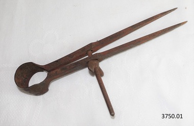
Instrument - Dividers, 1930-1955's
... . Used to measure and mark reoccurring distances. This set... and measuring set of dividers Sovereign of the sea Ship model Hobby Ship ...This set of dividers was used for measuring and marking details in the planning making of components for the ship model Sovereign of the Seas. It is part of a collection of objects used by Jim Williams, maker of fine ship models from about 1930-1955. Most of the components for the models, as well as many of the tools, were handmade by Jim Williams. Jim’s family has donated the ship model “Sovereign of the Seas” and many tools, accessories and documents used in the making of this and other ship models have been donated to Flagstaff Hill Maritime Village. Ship model of HMS Sovereign of the Seas, scale model of 17th Century English war ship, was handmade and carved from plans, enclosed in airtight glass case. All components of that model, including even the smallest pulleys, were hand crafted using tools designed and made by Jim. Outstanding details include functional rigging and moving cannons. Please see our record 3732 of the mode Sovereign of the Seas for further details of the ship and the maker.This set of dividers is connected with the hobby and skill of ship model making that has been crafted as a leisure activity for many generations. The hobby is often chosen by serving and retired mariners who appreciate the connection with maritime history. These dividers were used by local Warrnambool man, Jim Williams, who was employed at Cramond and Dickson clothing store, and then at Fletcher Jones menswear for 27 years. It was used in making components for the model of the historic ship, the Sovereign of the Seas. The Sovereign of the Seas was a historic 17th century English war ship with important maritime heritage. Dividers, metal, adjustable with wingnut to hold in place. Used to measure and mark reoccurring distances. This set of dividers is part of a collection of tools and accessories once used by Jim Williams, maker of a series of ship models 1930-1955 including “HMS Sovereign of the Seas”.flagstaff hill, warrnambool, flagstaff hill maritime museum, maritime museum, shipwreck coast, flagstaff hill maritime village, great ocean road, jim williams, james bernard williams, ship model hobby, ship model tools, ship model making equipment, ship model making accessories, technical drawing instrument, dividers for drawing and measuring, set of dividers, sovereign of the sea, ship model, hobby, ship model tool, english war ship, measuring instrument -
 Kiewa Valley Historical Society
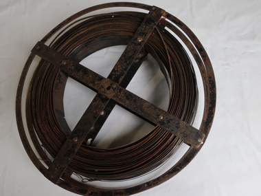
Surveyors Chain - Steel Band
... to measure distances when developing the land. surveyors surveyors ...A chain is a unit of length equal to 66 feet or 22 yards. This is a statute measure in the United Kingdom. One link is 100th part of a chain, which is 7.92 inches (20.1 cm). The chain and link became standard surveyors' units of length and crossed to the colonies from the United Kingdom. The chain is the unit of linear measurement for the survey of the public lands as prescribed by law. In Australia most building lots in the past were a quarter of an acre, measuring one chain by two and a half chains. Also street frontages, roads, laneways. The chain also survives as the length of a cricket pitch, being the distance between the stumps. Surveyors and residents of the Kiewa Valley used the Steel Band Surveyors Chain to measure distances when developing the land.Surveyors' steel band measuring tape, known as a 'standard band', or a 'steel band chain'.This chain consists of a long narrow strip of steel of uniform width of 3 mm and thickness of 0.3 to 0.6 mm. The chain itself is between 20 m and 30 m long.surveyors, surveyors chain, measurement of distance -
 Flagstaff Hill Maritime Museum and Village
Octant, Mid to late 19th Century
An octant is an astronomical instrument used in measuring the angles of heavenly bodies such as the sun, moon and stars at sea in relation to the horizon. This measurement could then be used to calculate the altitude of the body measured, and then the latitude at sea could also be calculated. The angle of the arms of an octant is 45 degrees, or 1/8 of a circle, which gives the instrument its name. Two men independently developed the octant around 1730: John Hadley (1682–1744), an English mathematician, and Thomas Godfrey (1704–1749), a glazier in Philadelphia. While both have a legitimate and equal claim to the invention, Hadley generally gets the greater share of the credit. This reflects the central role that London and the Royal Society played in the history of scientific instruments in the eighteenth and nineteenth century's. There were also two others who are attributed to having created octanes during this period, Caleb Smith, an English insurance broker with a strong interest in astronomy (in 1734), and Jean-Paul Fouchy, a mathematics professor and astronomer in France (in 1732) In 1767 the first edition of the Nautical Almanac tabulated lunar distances, enabling navigators to find the current time from the angle between the sun and the moon. This angle is sometimes larger than 90°, and thus not possible to measure with an octant. For that reason, Admiral John Campbell, who conducted shipboard experiments with the lunar distance method, suggested a larger instrument and the sextant was developed. From that time onward, the sextant was the instrument that experienced significant development and improvements and was the instrument of choice for naval navigators. The octant continued to be produced well into the 19th century, though it was generally a less accurate and less expensive instrument. The lower price of the octant, including versions without a telescope, made it a practical instrument for ships in the merchant and fishing fleets. One common practice among navigators up to the late nineteenth century was to use both a sextant and an octant. The sextant was used with great care and only for lunar sightings while the octant was used for routine meridional altitude measurements of the sun every day. This protected the very accurate and pricier sextant while using the more affordable octant for general use where it performs well. The invention of the octant was a significant step in providing accuracy of a sailors latitude position at sea and his vessels distance from land when taking sightings of land-based landmarks.Octant with metal handle, three different colored shades are attached, in wooden wedge-shaped box lined with green felt. Key is attached. Two telescope eyepieces are in box. Some parts are missing. Oval ink stamp inside lid of box, scale is graduated to 45 degrees. Ink stamp inside lid of box "SHIPLOVERS SOCIETY OF VICTORIA. LIBRARY"instrument, flagstaff hill, warrnambool, shipwrecked coast, flagstaff hill maritime museum, maritime museum, shipwreck coast, flagstaff hill maritime village, great ocean road, octant, navigation, nautical instrument, navigation instrument, john hadley, sextant, astronomical instrument -
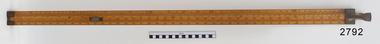 Flagstaff Hill Maritime Museum and Village
Head Rod, Dring & Fage, c. 1901
The Australian Customs Service, Melbourne, donated a set of gauging instruments, and Port Fairy Customs donated another instrument, the Sike’s Hydrometer, to Flagstaff Hill Maritime Village, all of which were no longer required. However these ullaging tools were in use for many years by Customs officials, called Gaugers. Ullaging is a term describing the measurement of the amount of liquid remaining in a container of spirits such as a cask or barrel. It can also measure the free space or head space remaining. The primary role of customs officers in Victoria was to calculate the tariff or excise duty payable on goods imported into Victoria. (Excise duty is a tax on goods produced within a country, and customs duty is imposed on imports.) Customs officers spent a great deal of their time measuring and weighing goods, and then calculating the amount of duty to be paid by the importer. The tariffs for different products varied, and officers consulted published lists. Calculating the duty payable on a barrel of brandy was a detailed task. The gauger had to measure the barrel to determine its volume. Barrels were irregular in shape, and finding the volume required several measurements and checking tables of figures. Alcoholic content was then measured with a hydrometer. The duty paid varied according to the alcoholic strength of the spirits. Uniform national customs and excise duties were operative in Australia from October 1901. These tools were still being used in Australia in the 1950’s. The Federal Government still imposes excise taxes on goods such as cigarettes, petrol, and alcohol. The rates imposed may change in February and August each year in response to changes in the consumer price index. ULLAGING TOOLS (1) Head Rod - this instrument measures the diameter of the heads (top and bottom ends) of a cask or barrel. The shaped brass pieces on the head rod enable the diameter of a barrel to be measured inside the chimes at the head end. The slide rule could then be used to calculate the internal volume of the barrel. On the reverse side is a set of ullaging scales, used like those on any ullaging rule, to calculate the volume of liquid in a partially filled barrel. (2) Bung Rod – this instrument measures the diameter of a cask or barrel when it is lying on its side. It is a rod that fits into the ‘bung’ hole of a cask and is long enough be extended to reach the opposite side of the cask. The brass sliding pointer can be moved to mark the ‘wet’ line. When the rod is removed the bung measurement can be read from the scale on the rod. (3) Long Calipers - this instrument measures the length of the cask between the heads. It has two rules sliding beside each other, each end having another piece of wood fixed firmly at right angles downwards then turned inwards at the ends so as to reach over the heads of the casks without touching the projecting ends. The centre pieces enable it to extend or contract, changing the distance between the two other parallel sides, the distance they are apart being shown by the rule on the sliding pieces. (4) Cross Calipers – this instrument is used to take the bung diameters of casks, or "the Cross " as it is called. This instrument has two rules sliding beside each other, each end having another piece of wood fixed firmly at right angles downwards, together forming a 3 sides of a rectangle with the centre pieces enabling it to extended or contracted, changing the distance between the two other parallel sides, the distance they are apart being shown by a the rule on the sliding pieces. (5) Sike’s Hydrometer – this instrument is used to gauge the strength of different alcoholic spirits when fitted with the different weights in the set. Every set is individually calibrated to ensure that it meets the exact Standard Weight and Measure compliance, then every piece in that set is stamped with the same number by the Calibrator, to ensure that the measurements are taken using the same hydrometer set. [References: A Handbook of Practical Gauging, Janes Boddely Keene of H.M. Customs, 1861, F. Pitman, London; Customs Act, Volume 2, No. 1, April 1999; Old Customs House website ] Head Rod, ullaging gauge. Long wooden rod made of three joined sections, brass hook on end, sliding centre section with hook, measurements marked along each section as on a slide rule. Used for measuring diameter of heads of casks in order for Customs to calculate excise (tax) on the contentsflagstaff hill, warrnambool, shipwrecked coast, flagstaff hill maritime museum, maritime museum, shipwreck coast, flagstaff hill maritime village, great ocean road, head rod, gauging rod, ullaging rods, measuring instruments, customs tax -
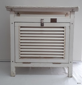 Flagstaff Hill Maritime Museum and Village
Equipment - Stevenson Screen, Thomas Stevenson, ca. 1910
Stevenson screens were first introduced in Australia in the 1880s and were widely installed by 1910. The screens have been used to shelter and protect thermometers and other meteorological instruments from rain and direct heat while the holes and double-louvre walls allowed air to flow around them. Sometimes other meteorological instruments were included in the weather stations, so there were different Stevenson Screen sizes. This authentic, original Stevenson screen was previously owned by the Australian Bureau of Meteorology and was used for many years for weather readings at the Cape Otway Light Station in southwest Victoria. The Lighthouse Keepers recorded the readings for minimum and maximum temperatures at 9 a.m. every day from January 1865 until April 1994. The equipment was sheltered in a Stevenson Screen from 1902 until April 15 1994, when the mercury thermometer was replaced by a platinum resistance probe within an Automatic Weather Station (AWS). This Stevenson screen is one of the two screens that then became redundant. The other Stevenson screen was kept to display to visitors. Lightkeepers were no longer required at the Cape Otway Light station either, due to the automated system. The meteorological instruments donated with the screen were used for measuring temperature and humidity. They are mounted on a metal bracket that fits across the screw holes on the screen’s internal frame. The glass-covered Relative Humidity (RH) sensor was made by the renowned precision instrument maker, Rotronic AG of Switzerland, which was founded in 1965. The firm made its first electronic temperature and humidity instrument in 1967. Meteorological records have been collected in Australia from the 1800s. The records were collated, published and used as a basis for weather forecasts. Many sectors, such as maritime and agriculture industries, have relied on these figures for making important decisions. The quality and placement of the meteorological instruments used to measure temperature and humidity are of utmost importance for accuracy. In early colonial times, there were no national standards for meteorological instruments that would allow for accurate figures and comparisons. Once the Bureau of Meteorology was established (around 1908 to 1910) the department installed Stevenson screens throughout Australia, many at lighthouses and light stations, and the measuring instruments were standardised. The Stevenson Screen was named after its inventor, Scottish Civil Engineer Thomas Stevenson (1818-1887) who was also the father of Robert Louis Stevenson, author. Stevenson developed the small thermometer screen around 1867. It had double-louvred walls around the sides and a top of two asbestos sheets with an air space between them and was thickly painted with a white coating that reflected the sun’s rays. This design was modified in 1884 by Edward Mawley of the Royal Meteorological Society. Standards were set for the locations of the screens and instruments, including their distance above ground level and the direction the door faced.Stevenson screens played a significant part in providing a standardised shelter for all meteorological instruments used by the Australian Bureau of Meteorology from about 1910 until 1994. The readings from the instruments gave the meteorological statistics on which weather forecasts throughout Australia were based. This Stevenson screen was used locally at Cape Otway, along the Great Ocean Road in southwest Victoria, so contributed towards our local forecasts and weather warnings.Stevenson screen, original, from the Australian Bureau of Meteorology’s weather station at the Cape Otway Lighthouse. The screen is a white wooden cupboard with a slanted cover raised above the top. The top has ten drilled ventilation holes, and the sides and door are made of downward-slanting double louvres. Two brass hinges join the door to the lower edge of the screen and a metal fitting at the top edge allows for a padlock closure. The screen is supported on four short legs, each with a hole drilled from side to side for fitting to a frame. Inside the screen are two wooden frames fitted with hooks and screws. The floor has three boards; one across the back and one across the front at the same level, and a board wider than the space between these boards is fitted higher, overlapping them slightly. Inside the screen, a pair of electronic instruments with short electric cables is mounted on a metal bracket with drilled holes in it. One of the instruments is a Relative Humidity (RH) probe. It is 26 cm long and is a glass tube with a filter on one end and an electrical connection on the other. It has inscriptions on its label, showing that was made by Rotronic AG, Switzerland. The other instrument is a Resistance Temperature Device (RTD) thermometer. It is 22.5 cm long and has a narrow metal probe joined to a hexagonal metal fitting. A brass plate on the front of the screen has impressed inscriptions. The screen is Serial Number 01/C0032, Catalogue Number 235862.Stamped into brass plate "CAT. NO. / 253862 / SERIAL NO. 01/C0032" On instrument’s electrical fitting; “CD2” [within oval ‘+’ above S] “Serie693 op65 / 220/380V~16A” On instrument’s glass; “rotronic ag” “SWISS MADE” “CE / CH-8303 / Bassersdorf” Symbol for [BARCODE] “ART NO MP 101A_T4-W4W” “POWER 4.8.30VDC“ “OP. RANGE: 0-100%RH/-40+60° C” “OUT H 0-100% 0-1V” “OUT T -40+60°C -0.4..+0.6V” “SERIE NO 19522 009”flagstaff hill maritime museum and village, warrnambool, maritime museum, maritime village, great ocean road, shipwreck coast, cotton region shelter, instrument shelter, thermometer shelter, thermoscreen, thermometer screen, measuring instruments, meteorological instrument, weather recording, weather station, lighthouse equipment, light station equipment, stevenson screen, marine instruments, mercury thermometer, platinum resistance probe, aws, automatic weather station, rotronic ag, swiss made, meteorological device, weather forecast, weather prediction, weather records, meteorological forecast, meteorological record, australian bureau of meteorology, bureau of meteorology, bureau, bom, relative humidity, rh, relative humidity probe, resistance temperature device, rtd, thermometer, temperature, humidity, cape otway, cape otway lighthouse, cape otway light station, rotronic, switzerland, swiss instrument, thomas stevenson, double-louvered walls, edward mawley, royal meteorological society, 01/c0032, serial number, cat. no. 235862, serial no. 01/c00323 -
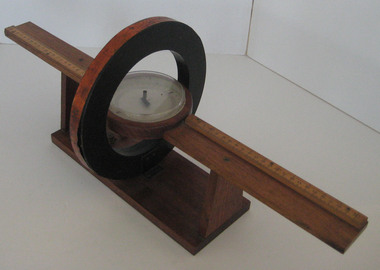 Federation University Historical Collection
Equipment - Scientific Instrument, Tangent Galvanometer
Used for measuring electric current. It works by using a compass needle to compare a magnetic field generated by the known current to the magnetic field of the Earth.A "compass rose" type of horizontal full-circle scale, with 4 0-90 unit quandrants. Balanced, free-floating needle. Located centrally wired to a vertical coil. Horizontal distance scales, one each side and perpendicular to the core. All mounted on polished wood base, equipped with 3 terminal posts. Materials: glass, wood, metal.elementary, physics, experiment, galvanonometer, ballarat school of mines, scientific instruments -
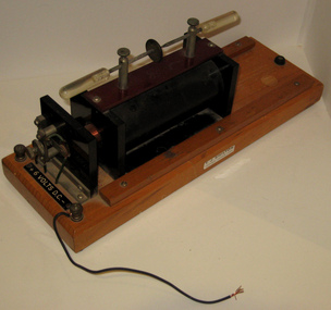 Federation University Historical Collection
Scientific Instrument, Induction Coil
An induction coil consists of two coils of insulated copper wire wound around a common iron core. One coil, called the primary winding, is made from relatively few (tens or hundreds) turns of coarse wire. The other coil, the secondary winding, typically consists of many (thousands) turns of fine wire. An electric current is passed through the primary, creating a magnetic field. Because of the common core, most of the primary's magnetic field couples with the secondary winding. The primary behaves as an inductor, storing energy in the associated magnetic field. When the primary current is suddenly interrupted, the magnetic field rapidly collapses. This causes a high voltage pulse to be developed across the secondary terminals through electromagnetic induction. Because of the large number of turns in the secondary coil, the secondary voltage pulse is typically many thousands of volts. This voltage is often sufficient to cause an electric spark, to jump across an air gap separating the secondary's output terminals. For this reason, induction coils were called spark coils. The size of induction coils was usually specified by the length of spark it could produce; an '8 inch' (20 cm) induction coil was one that could produce an 8 inch arc. (http://en.wikipedia.org/wiki/Induction_coil)A metal and plastic object on a timber stand. In an induction coil the distance between the plates is often used to measure the voltage of the spark since the air breaks down at 30 000 volts per centimetreballarat college of advanced education, scientific instrument, induction coil, scientific instruments, electricity -
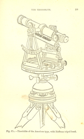 Federation University Historical Collection
Book, Bennett H. Brough, A treatise on Mine-Surveying, 1904
... , measurement distances, the chain, rods, steel bands, measuring wheel..., measurement distances, the chain, rods, steel bands, measuring wheel ...The author, Bennett H. Brough was an associate of theRoyal School of Mines, a member of the COuncil of the Institution of Mining Engineers, a fellow of the geological society and of the Institute of Chemistry, a member of the Mining Institute of Cornwall, and a former instructor of mine-surveying at the Royal School of MinesRed had covered book 372 pages - part of Griffin's Mining Series. Contents include general explanatinos of surveying, an historical sketch, mineral deposits, mining terms, measures of length, measurement distances, the chain, rods, steel bands, measuring wheel, Miner's Dial, Magnetic needle, Fixed needle, German Dial, theodolite, traversing underground. Surface-surveys. plotting the survey, calculation of area, leveling, Telescope, Setting out, Mine-Surveying Problems, Mine Plans, Photographic Surveying, examination Surveying. Illustrations include: Whitelaw's Dial (Fig 22), Theodolite of the American Type with Hoffman tripod head, (fig 37a)mining, surveying, miner's dial, chain, survey, theodolite, scientific instruments