Showing 786 items matching "specification"
-
 Southern Sherbrooke Historical Society Inc.
Information folder - "The Bungalow"
Material donated by current owner, Inga Melgaard, 20th November 2006.Folder containing information pertaining to "The Bungalow", Belgrave Heights. Material supplied by current owner, Inga Melgaard, on 20th November, 2006. Contents:/"Specifications of a bungalow for W.J. Murrell's (sic) Esq" drawn up by Leslie J.W.Reed, Architect, "Kaleno", 45 Thanet St, Malvern, dated September 1915./House sale advertisement, showing photograph, floor plan, description and location map./Subdivision maps, 6 sheets./Certificate of Title, Vol. 3892, Fol.778347, dated 28th May 1915, William Joseph Murrells./Certificate of Title, Vol. 6939. Fol. 1387757, dated 31st October, 1946, Agnes Murrells and Nora Murrells./CD containing Certificates of Title, photos taken in 1994 and photos taken by current owner, and a list of previous owners, 1915-1979./Copy of above list. -
Moorabbin Air Museum
Archive (Item) - Box WP1 Prowse Collection See details under Description, Box WP1 Prowse Collection
-
 Melbourne Tram Museum
Legal record, Christie & Gardiner, Consulting Engineer', "Contract between Footscray Tramway Trust and The Australian General Electric, 31/07/1919 12:00:00 AM
Set of documents sewn within a green folder titled "Contract between The Chairman and Members of the Footscray Tramway Trust and The Australian General Electric Co. Queen St Melbourne for the supply, delivery and Erection of Rotary Converters, Transformers and Switchgear for the Footscray Tramway Trust" containing: 1 - "Footscray Tramways Trust - General Conditions, Specifications and Forms for Tendering - Tender for the Supply Delivery and Erection of Rotary Converters, Transformers and Switchgear", Schedule of Prices, Tender Form, Schedule of documents, contract dated 31/7/1919, includes the seal of the FTT and copies of some 10 letters clarifying matters between the time of the tender and documentation. Documents have been signed and sealed. See page 5 bottom right hand corner for the FTT Seal. Documents prepared by Christie & Gardiner, Consulting Engineers, 97 Queen St Melbourne. Parts of the document have scanned to pdf.Has in pencil in the top right hand corner "49"trams, tramways, ftt, footscray, rotary converters, electrical engineering, electrical equipment, tenders, contracts -
 Ballarat Heritage Services
Photograph - Photograph - Black and White, Hepburn Springs Swimming Pool
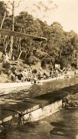
The Hepburn Pool was built in Spring Creek during the 1930s by the Zelmans of Bellinzona Guest House. Alberto Zelman paid for local workers to construct the pool to their specifications so the visitors to local guest houses could swim on hot days. The Hepburn Pool was used for the Victorian Swimming Championships, with 6 stones marked at one end for each lane. It is 50 yards long, the length required for competitions. In 1935 the Hepburn Amateur Swimming Club organised their first swimming carnival, the meeting conducted by the Victorian Amateur Swimming Association, In 1969 the Daylesford Olympic Swimming Pool was constructed so this 'old swimming pool' was neglected. Fortunately in 1993 local volunteers associated with the Savoia Hotel returned the pool to its former glory with the help of old photos and a lot of hard work. Two well known swimmers swam at the pool in the Victorian swimming Championships, they were Annette Kellerman and Frank Beaurepaire. The Pool was named Victoria's Favourite Built Place in 2004 as part of the Victorian Government's involvement in the International Year of the Built Environment. It was included on the Victorian Heritage Register following a nomination and comparative analysis of pre Olympic Swimming Pools in Victoria by Lisa Gervasoni.Black and white photograph of the Hepburn Pool in Spring Creek, including the diving board.hepburn springs swimming pool, hepburn springs, hepburn pool, pre-olympic swimming pools, albert zelman, bellinzona, annette kellerman, frank beaurepaire, victorian amateur swimming association, hepburn amateur swimming club -
 Wodonga & District Historical Society Inc
Memorabilia - China Souvenir Plate Shire Chambers Wodonga, Westminster Fine China Australia, C. 1957 - 1962
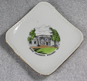
After meeting for 14 years in rented premises, in the Prince of Wales Hall, Wodonga Council built its first Shire Hall on the corner of High and Elgin Streets in 1890. The first Shire Hall was demolished in 1971. The second building, Wodonga’s new Municipal Offices in Woodland Grove were used for the first time by Wodonga Councillors on 7th August 1957. The Woodland Grove building has since been used for a range of purposes, most recently as a café, but is currently unoccupied. The third purpose-built council chambers were opened in November 1976 with the first council meeting there on 1st December 1976. Westminster Fine China Australia started in the Melbourne suburb of Cheltenham at 7 Arnold Street, in 1954 by Stanley Rogers and Son Ltd. They initially used imported blanks from Japan, which were made to their specifications, and which were then decorated locally. They produced a standard range of shapes for souvenir ware, later expanding into a wide range of tea sets, dinnerware and many other styles of china ware. The Abbey mark, based on Westminster Abbey in London, was used from the start of production until about 1962.Woodland Grove was named in honour of Wodonga Shire’s first president, John Woodland. The building depicted served as the centre of municipal government for approximately 20 years, throughout the 1960s and 1970s. Woodland Grove is a central point in the Wodonga CBD and a focus for many civic and cultural activities.Small square plate with gold trim and central coloured image of Wodonga Shire Chambers. The trademark of Westminster Fine China Australia is on the under side of the plateOn front beneath image "SHIRE CHAMBERS WODONGA VIC" Underneath the plate, surrounding an drawing of Westminster Abbey "FINE CHINA/WESTMINSTER CHINA /AUSTRALIA/ 7" municipal offices, woodland grove wodonga, souvenirs, westminster china -
 Trafalgar Holden Museum
Vehicle - VZ Holden Executive, 2004
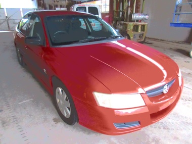
Released in August 2004, the VZ series was a minor facelift of the previous VY series that featured a new V6 engine in different tune guises. The powerplants included 175 and 190 kW (235 and 255 hp), 3.6-litre Alloytec V6 engines in place of the older 3.8-litre Ecotec V6. Other changes to the V6 was the loss of the supercharger that was included in the S models The VZ Commodore was available in several model variations, most of which carried over from the VY range, with the exception of the newly introduced SV6, a specification level that replaced the S range. All models in the Commodore range (Executive, Acclaim, Berlina, Calais, SV6, SV8 and SS) were available as sedans. The advanced 3.6-litre Alloytec engines were more powerful, responsive and fuel-efficient than the outgoing Ecotec V6. To achieve 190 kW (255 hp), the Alloytec V6 gains variable valve timing on both inlet and exhaust sides as well as a dual stage intake manifold, while the 175 kW (235 hp) version retains variable valve timing on the inlet side only. Sales of the VZ series failed to match those of the preceding VY in light of rising small car sales, higher fuel prices and growing interest in the whole new replacement, the VE series. Selected models bring advanced active safety features that electronically assist the driver to maintain vehicle control in emergency situations. VZ Holden 4 door sedan with red body paint and fabric upholsteryLion badge front grille,V6 badge on mudguards. Executive badge on RHS of boot and Comnmodore on LHS. Lion badge on middle of bootvehicle, vz holden, car -
 Warrnambool RSL Sub Branch
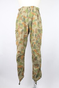
Trousers, Australian Defence Apparel, 2015
These trousers are part of a Disruptive Pattern Combat Uniform issued by the Australian Airforce to Bernard Farley during service. This uniform type was used in base and field activities and was replaced in 2014 by the General Purpose Uniform as the uniform worn during general base duties and in non-warlike environments.This item has social significance, as an item of uniform worn by Warrnambool RSL community member and Secretary (2019), Bernard Farley during service with the Australian Airforce. The item is a representative example of previously standard issue Airforce uniform and is in excellent condition. As a set, the uniform has aesthetic significance in it’s design, incorporating the Disruptive Pattern style of camouflage which has its roots in the 1980s and continues to be adapted into uniform design by the Defence Force.Disruptive Pattern trousers in five colours of green and brown. Long pants with elasticised drawstring fastener at ankle and velcro adjustment fasteners at the waist. Pants take a straight leg style and bears several pockets: two thigh level pockets with zippered horizontal opening, two open hip pockets on the front, one open pocket on the reverse right hand side with blue plastic button fastener. Five large belt loops encircle the waist and there is a zippered fly, secured at the top with a blue plastic button.Label on interior front right of trousers reads: “A13/ADA/VICTORIA 2008/(broad arrow)/SPECIFICATION ARMY (AUST)6542/NSN: 8415 66 152 1059/SIZE: 95 S/NAME/SERVICE NO/75% COTTON 25% POLYESTER/WARM MACHINE WASH 40*C/RINSE WELL, WARM IRON/DO NOT IRON OVER HOOK AND PILE/DO NOT BLEACH/DO NOT STARCH/MAY BE TUMBLE DRY 40*C/MADE IN AUSTRALIA” The name “FARLEY” is also handwritten on the back interior waist band of the trousers. camouflage, general purpose uniform, airforce, uniform, australian defence force -
 Forests Commission Retired Personnel Association (FCRPA)
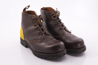
Uniform - Safety Boot (Yellow back), Oliver Stevens in Ballarat, circa 1982
These boots were manufactured by Oliver Stevens in Ballarat to the Forests Commission's own specification. Safety boots were a bit "hit and miss" back in 1981. As well as the steel toe caps these boots had a screwed, glued and stitched Sherpa-pattern rubber nitrile sole. The sole was oil resistant and didn't melt on hot coals. The yellow heels signified safety boots. There were two styles with different leather and staff were all personally fitted and given their choice of style. The only thing that has fundamentally changed over 40 years is there is much more choice and comfort in boots today. These boots proved to be the catalyst for boot manufacturers realising there was a market outside of the armed forces not being served. Ankle injuries along with elastic sided boots were virtually eliminated by these boots. The iconic Tasmanian company, Blundstone, had a work boot called "Forester" at the time. It had won an Australian Design Award and had a bonded Sherpa sole. Unfortunately, the soles tended to separate from the boot under field test conditions. Eventually they perfected the process Oliver Stevens' main issue was not being able to recruit enough workers to meet the increased demand. Info: Trevor Brown.First safety boots issued to Victorian forest firefightersYellow Back safety boots with leather laces. FCV marked on the heel fire fighting, bushfire, forests commission victoria (fcv), protective clothing -
 Ballarat Tramway Museum
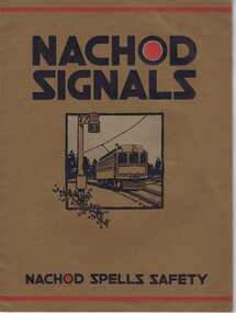
Book, Nachod and United States Signal Co, "Nachod Signals", c1918
Sixteen page book with brown paper covers in addition. Pages printed on art paper with a red overprint on some pages. Titled "Nachod Signals", published by the Nachod and United States Signal Co. Inc, successors to Nachod Signal Co of Louisville Kentucky. Has a list of dates on page 2, of patents, the last being 5/2/1918. Has on the bottom of most pages "Nachod Spells Safety" Details the Nachod signals system, type CD with the details of the operation, elements of the system, signal layout, installation and wiring, trolley Contactors, signal aspects, relays, assembly on poles, ordering information, fuses, special designs and modifications, information in ordering, quantity and list of material, and specification details of the Type P on the last three pages. See also Reg Item 3318 for another US company system, received by ESCo at the same time. Indicates that the Nachod and US Signal Company had merged.On top of page 1 "Ballarat Tramway Preservation Society Catalogue No. 3" in black ink and overstamped ESCO's date stamp of 4 Nov. 1926. On page 2 at bottom :"Nachod and United States Signal Co. Inc successors to" has been overstamped. trams, tramways, signals, railways, tramways -
 Melbourne Tram Museum
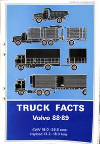
Manual, Volvo, "Volvo Truck facts – 88-89", "Volvo bus data sheet set", "Lubrication recommendations for Volvo buses – post 1950", "Volvo Service bulletin – service intervals for oil and filter", "Volvo service bulletin – Lubricating oil and recommendations.", "Volvo turbo diesel and its Bosch injection system", 1970's
Set of 7 manuals, documents, instructions regarding truck, bus, motors produced by Volvo. .1 - Volvo Truck facts – 88-89 - approx. 70 pages with diagrams, card covers. .2 - Volvo bus data sheet set - 9 foolscap sheets with data on chassis, servicing and general specifications. .3 - Lubrication recommendations for Volvo buses – post 1950 - Foolscap - approx. 40 sheets. .4 - Volvo Service bulletin – service intervals for oil and filter - single A4 sheet. .5 - Volvo service bulletin – Lubricating oil and recommendations - single foolscap sheet, .6 - Volvo turbo diesel and its Bosch injection system - manila folder containing about a 30 pages document titled "The Volvo TD100A Engine". .7 - Letter to MMTB 1977 re oils from Volvo Australia - correspondence - 10 sheets - dated 3/6/1977, with a note saying it does not answer the question.trams, tramways, volvo, buses, instructions, manual, equipment, maintenance -
 Federation University Historical Collection
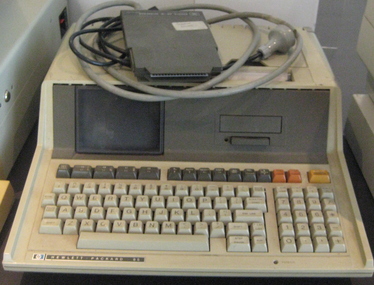
Equipment - Computer, Hewlett Packard, Personal Computer HP85A, 1979 (estimated)
The HP-85A was Hewlett Packard's first Series 80 microcomputer, introduced about 1979. It had a keyboard, a dual alpha/graphics monochrome display, a bidrectional alphanumerics and graphics printer, and mass storage tape drive all integrated into a marvelously designed and compact case. It's operating system was seemlessly integrated with a powerful BASIC programming language that included intuitive graphics and input/output capabilities. The HP-85A was also wonderfully expandable through four ports on the back of the case for adding plug in ROMS and modules. Specifications CRT DISPLAY Size: 12.7 cm (5 in.) diagonal Alphanumeric capacity: 16 lines x 32 characters Graphics capacity: 192 x 256 dots Scrolling capacity: 64 lines Character set: 256 characters; set of 128 + same set underscored Character font: 5 x 7 matrix Intensity: adjustable Cursor: underscore BASIC LANGUAGE AND OPERATING SYSTEM Standard ROM - 32K bytes Maximum add-on ROM - 48K bytes CRT memory RAM - 8K bytes USER READ/ WRITE MEMORY Standard - 16K bytes Maximum - 32K bytes TOTAL MEMORY Standard - 56K bytes Maximum - 120K bytes (Information from http://www.ebbsoft.com/hp/85a.htm)Personal computercomputers, monitor -
 Vision Australia
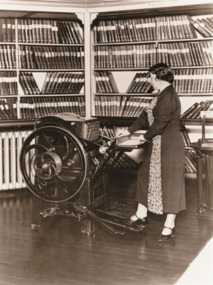
Photograph - Image, Minnie Crabb operating the Crabb-Hulme Braille printing press, circa 1934
Mary Halls "Minnie" Crabb (1885-1974) was the niece of the first librarian (May Harrison) for the Victorian Association of Braille Writers. After her aunt's death in 1912, Miss Crabb took on the role of librarian for the constantly expanding collection. In 1934, the Victorian Association of Braille Writers annual report advised that it had acquired a Crabb-Hulme Braille Printing Press. Two years in development, the Press was designed by Miss Crabb and built to her specifications by Mr Hulme. Invented to produce ephemeral material quickly, such as programs, catalogues and newsletters, it provided more opportunities for information to be quickly sent out to Braille readers. The daughter of James Hall Crabb, who ran the Prahran Telegraph from1882 until his death and the niece of J.M. Yelland who took over the paper until he sold it in 1895, Minnie would have seen printing presses in her youth and recognised the usefulness when producing large numbers of ephemeral materials. In March 1944, Miss Crabb retired from the library, in 1956 she married Charles Foster and she lived until in the St Kilda area until her passing in 1974, aged 89. This iconic image of Miss Crabb using the press has appeared in many reports since.High quality image of Minnie Crabbvictorian association of braille writers, minnie crabb -
 Wodonga & District Historical Society Inc
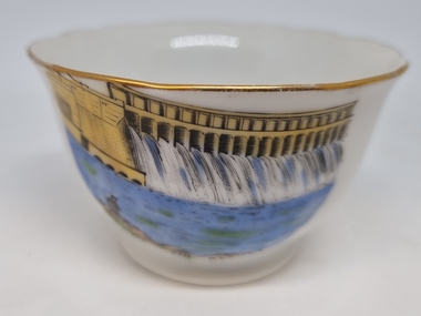
Souvenir - China Bowl - Hume Weir, Albury, Westminster Fine China Australia, c1957
This item is from a collection donated by descendants of John Francis Turner of Wodonga. Mr. Turner was born on 6 June 1885. He completed all of his schooling at Scotts Boarding School in Albury, New South Wales. On leaving school, he was employed at Dalgety’s, Albury as an auctioneer. In 1924 John was promoted to Manager of the Wodonga Branch of Dalgety’s. On 15/03/1900 he married Beatrice Neal (born 7/12/1887 and died 7/2/1953) from Collingwood, Victoria. They had 4 daughters – Francis (Nancy), Heather, Jessie and Mary. In 1920, the family moved From Albury to Wodonga, purchasing their family home “Locherbie” at 169 High Street, Wodonga. "Locherbie" still stands in Wodonga in 2022. The collection contains items used by the Turner family during their life in Wodonga. Westminster Fine China Australia started in the Melbourne suburb of Cheltenham at 7 Arnold Street, in 1954 by Stanley Rogers and Son Ltd. They initially used imported blanks from Japan, which were made to their specifications, and which were then decorated locally. They produced a standard range of shapes for souvenir ware, later expanding into a wide range of tea sets, dinnerware and many other styles of china ware. The Abbey mark, based on Westminster Abbey in London, was used from the start of production until about 1962.The Hume Weir was constructed in the late 1920s and was a critical state in the development of water management in the Murray Darling Basin. At the time of its construction it was the largest water reservoir in the British Empire. Small bowl with gold trim printed with an image of the Hume Weir, Albury. The trademark of Westminster Fine China Australia is on the under side of the plate.On front beneath image "Hume Weir, Albury" Underneath the plate, surrounding an image of Westminster Abbey "FINE CHINA/WESTMINSTER CHINA /AUSTRALIA" souvenirs, westminster china, hume weir australia, memorabilia albury -
 Bendigo Historical Society Inc.
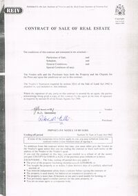
Document - PETER ELLIS COLLECTION: CONTRACT OF SALE
Copy of Contract of Sale of Real Estate and associated papers for property located in Flora Lane, Flora Hill which was purchased by Peter Ellis on 26 May 1993. Contract is in booklet with other loose papers. Contract includes General Conditions, Particulars of Sale, Special Conditions, Guarantee, Vendors Statement to the Purchaser, Shire of Strathfieldsaye Land Information Certificate, Planning Certificate Request for Building Approval Particulars, Coliban Region Water Authority Information Statement, Property Inquiry Application Form, Request for Property Information from Vic roads, Advice on Mine Subsidence Hazard (Department of Energy & Minerals), Map, Copy of Certificate of Title and Folder Numbers. Loose pages include Building Control Act 1981 Inspection Notice, two plans of building, Three plans (Coliban Water Asset Location) of Flora Lane where property is situated, 2 dated 13/11/2007 (have New Carport drawn beside house) and 1 dated 22/11/2007. Last page has specifications for car port.bendigo, house, peter ellis oam, peter ellis collection, reiv, law institute of victoria, real estate institute of victoria ltd, e j gannaway, peter n ellis, ray white bendigo pty ltd, e m monotti & son, rogers and every, craig watts, shire of strathfieldsaye, coliban region water authority, sec, g & fc of vic, telecom, vicroads, bruce l phillips, k deps?, department of energy and minerals, robert james sanderson, t flanagan, land titles office victoria, harston partridge & co pty ltd -
 Orbost & District Historical Society
maps, early 1900s
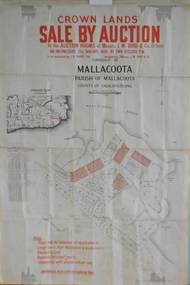
796.1 - Crown Land Sale by auction in the township of Mallacoota on Wednesday January 1920 at 2pm. 796.2 - Snowy River farms , 630 acres of river flat land at Orbost on Wednesday April 28, 1909 at 2.30pm. 796.3 - Famous Orbost Flats - "Important Sale of Snowy River Land" , 900 acres subdivided into 13 choice farms on Wednesday 1st December 1920 at 2.30pm. 796.4 - "Second Great Sale in James' Subdivision", adjoining town of Orbost on 16th May, 1919 at 2pm. 796.5 - "Subdivisional Sale Brooklands Estate", 5 rich Snowy River farms on Wednesday 23rd February at 2.30 at Orbost on account of James Hossack Esq. 796.6 - "Subdivisional sale of Splendid Residence Sites and Handy Small Paddocks" adjoining the progressive town of Orbost on 5th March 1915 at 11am at the rooms of H.James & Co. 796.7 - This is a contract drawing on waxed paper. Crossing near Harbecks Cunninghame Signed and traced N. Anderson 17/11/00. 796.8 - A plan and specification on waxed paper. Shire of Orbost Cunninghame Road - signed by the shire engineer. 796.9 - This is a hand drawn map of Orbost Cunninghame Road, November 1896. 796.10 - This is a hand drawn cross-section of a culvert on the Orbost Cunninghame Road. 796.11 - This is a plan of a culvert on Tabbara Road, 13th January 1899 796.12 - This is a poster for an "Important Subdivisional Sale' for land near Orbost Bridge, on Wednesday 16th March 1921 at the rooms of H. James & Co. These documents are an important part of Orbost history in that they show how the town and surrounding areas were subdivided for farming and residential settlement.A set of twelve maps, plans and land sale posters .orbost-land-1900s maps posters h.james -
 Flagstaff Hill Maritime Museum and Village
Equipment - Foghorn, 20th century
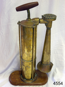
A marine foghorn gives an audible navigational signal to warn vessels of dangers, hazards and the presence of other vessels in fog conditions. The foghorn signal is a series of long and short sounds with short or long pauses between them. These common signals conform to a code called the International Regulations for Preventing Collisions at Sea and provide such information as whether the vessel is under sail or motor, large or small, aground or at anchor. The designs of foghorns vary but they all use a column of air to make a loud sound. Some use vibrating plates or metal reeds, others force air through holes in a revolving cylinder or disc, sounding like a siren, and some use a clockwork mechanism to open the valves that let the air into the horn. They are usually built to meet particular specifications e.g. U.S.C.G. (US Coast Guard). This Tyfon plunger foghorn has a horizontal handle attached to a vertical rod that moves up and down inside a cylinder. When the handle is plunged down, in a similar way to a bicycle pump, the air is forced out of the bottom of the cylinder into a pipe with a bell-shaped horn on the end, making a loud, low sound. The wider base of the cylinder helps to keep it stable. The original type Tyfon foghorns were manufactured in about 1910 by Kochums Mechanical Workshop (Kockums Mechanical Werkstad, Ltd.), Malmo, Sweden. The company was established in 1840, became a Limited company in 1866, and established a shipyard at the Port of Malmo, Sweden, in 1870. The civilian ship production in Malmo ceased in 1987. As well as building ships the company built large industrial and agricultural machinery and maritime goods.this replica foghorn represents the design of a Swedish, Tyfon model 1910. It is an example of the type of safety equipment used on marine vessels to signal other vessels and signal to land. Replica foghorn; portable marine, plunger operation. It has a brass cylinder and adjustable brass horn. The plunger handle and base are wooden. Inscriptions are on the plaque on the horn and moulded into the air intake. Facsimile of a Kockums of Malmo, Sweden, Tyfon model 1910 Fog Horn.Impressed into the attached plaque "KOCKUMS MLK. VERKSTAD / MALMO SWEDEN" and "TRADE TYFON MARK" Also added to the plaque individually "288938" Molded around the circumference of the air intake "TYFON PATENT"flagstaff hill, warrnambool, shipwrecked coast, flagstaff hill maritime museum, maritime museum, shipwreck coast, flagstaff hill maritime village, great ocean road, foghorn, fog horn, tyfon foghorn, kockums mlk verkstad, malmo sweden, replica, warning signal, safety equipment, ship's equipment -
 Eltham District Historical Society Inc
Album - Photograph, J.A. McDonald, Dixons Creek Road, June 1957
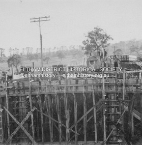
Bridge over Dixons Creek Job 56FD330 June 1957 Formwork for Dixons Creek pier completed Advertising (1957, January 19). The Argus (Melbourne, Vic. : 1848 - 1957), p. 33 (Col. 9). Retrieved August 24, 2022, from http://nla.gov.au/nla.news-article71777065 SHIRE OF ELTHAM. Loan No. 27.-Notice of Intention to Borrow Sum of £ 15,000 for Permanent Works and Undertakings. - Notice is hereby given, that the Council of the Shire of Eltham proposes to borrow the sum of £15,000 on the credit of the municipal revenues of the president, councillors, and ratepayers for the said shire, such sum to be raised by the Issue of debentures in accordance with the provisions of the Local Government Acts. 1. Maximum rate of interest that may be paid is £5/10/ per cent, per annum. 2. The purposes for which the loan is to be applied are: Construction of Sanitary Conveniences at Shire Office, Council's contribution towards costs of Dixons Creek Bridge, Construction of Mt. Pleasant rd., Construction of Cherry Tree rd. 3. The period of the loan shall be 10 years. 4. Moneys borrowed will be repayable by providing out of the Municipal Fund twenty half-yearly instalments of approximately £985/1/6 each, including principal and interest on the first day of October and the first day of April during the currency of the loan. The first Instalment shall be payable on the first day of October 1957. 5. Such moneys shall be repayable at the Commercial Bank of Australia Limited, Melbourne, or at the Council's bankers for the time being in Melbourne. The plans and specifications and the estimates of the costs of the proposed works and a statement showing the proposed expenditure of the moneys to be borrowed are open for inspection at the Shire Office, Eltham. R. J. HAM. Shire Secretary.Record of various Shire of Eltham infrastructure works undertaken during the period of 1952-1962 involving bridge and road reconstruction projects, sometimes with Eltham Shire Council Project Reference numbers quoted. It was during this period that a number of significant improvements were made to roads and new bridges constructed within the shire that remain in place as of present day (2022). In many situations, the photos provide a tangible visible record of infrastructure that existed throughout the early days of the Shire. The album was put together by or under the direction of the Shire Engineer, J.A. McDonald.infrastructure, road construction, shire of eltham, bridge construction, dixons creek bridge, dixon's creek road, 1957-06 -
 Eltham District Historical Society Inc
Album - Photograph, J.A. McDonald, Dixons Creek Road, June 1957
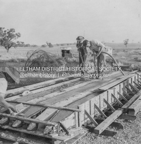
Piles being cast 1957 P. Morris on vibrator Advertising (1957, January 19). The Argus (Melbourne, Vic. : 1848 - 1957), p. 33 (Col. 9). Retrieved August 24, 2022, from http://nla.gov.au/nla.news-article71777065 SHIRE OF ELTHAM. Loan No. 27.-Notice of Intention to Borrow Sum of £ 15,000 for Permanent Works and Undertakings. - Notice is hereby given, that the Council of the Shire of Eltham proposes to borrow the sum of £15,000 on the credit of the municipal revenues of the president, councillors, and ratepayers for the said shire, such sum to be raised by the Issue of debentures in accordance with the provisions of the Local Government Acts. 1. Maximum rate of interest that may be paid is £5/10/ per cent, per annum. 2. The purposes for which the loan is to be applied are: Construction of Sanitary Conveniences at Shire Office, Council's contribution towards costs of Dixons Creek Bridge, Construction of Mt. Pleasant rd., Construction of Cherry Tree rd. 3. The period of the loan shall be 10 years. 4. Moneys borrowed will be repayable by providing out of the Municipal Fund twenty half-yearly instalments of approximately £985/1/6 each, including principal and interest on the first day of October and the first day of April during the currency of the loan. The first Instalment shall be payable on the first day of October 1957. 5. Such moneys shall be repayable at the Commercial Bank of Australia Limited, Melbourne, or at the Council's bankers for the time being in Melbourne. The plans and specifications and the estimates of the costs of the proposed works and a statement showing the proposed expenditure of the moneys to be borrowed are open for inspection at the Shire Office, Eltham. R. J. HAM. Shire Secretary.Record of various Shire of Eltham infrastructure works undertaken during the period of 1952-1962 involving bridge and road reconstruction projects, sometimes with Eltham Shire Council Project Reference numbers quoted. It was during this period that a number of significant improvements were made to roads and new bridges constructed within the shire that remain in place as of present day (2022). In many situations, the photos provide a tangible visible record of infrastructure that existed throughout the early days of the Shire. The album was put together by or under the direction of the Shire Engineer, J.A. McDonald.infrastructure, road construction, shire of eltham, bridge construction, dixons creek bridge, dixon's creek road, 1957-06, p. morris -
 Eltham District Historical Society Inc
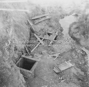
Album - Photograph, J.A. McDonald, Dixons Creek Road, June 1957
Dixons Creek Road P. Morris – Contractor Dixons Creek (North) abutment 1957 Advertising (1957, January 19). The Argus (Melbourne, Vic. : 1848 - 1957), p. 33 (Col. 9). Retrieved August 24, 2022, from http://nla.gov.au/nla.news-article71777065 SHIRE OF ELTHAM. Loan No. 27.-Notice of Intention to Borrow Sum of £ 15,000 for Permanent Works and Undertakings. - Notice is hereby given, that the Council of the Shire of Eltham proposes to borrow the sum of £15,000 on the credit of the municipal revenues of the president, councillors, and ratepayers for the said shire, such sum to be raised by the Issue of debentures in accordance with the provisions of the Local Government Acts. 1. Maximum rate of interest that may be paid is £5/10/ per cent, per annum. 2. The purposes for which the loan is to be applied are: Construction of Sanitary Conveniences at Shire Office, Council's contribution towards costs of Dixons Creek Bridge, Construction of Mt. Pleasant rd., Construction of Cherry Tree rd. 3. The period of the loan shall be 10 years. 4. Moneys borrowed will be repayable by providing out of the Municipal Fund twenty half-yearly instalments of approximately £985/1/6 each, including principal and interest on the first day of October and the first day of April during the currency of the loan. The first Instalment shall be payable on the first day of October 1957. 5. Such moneys shall be repayable at the Commercial Bank of Australia Limited, Melbourne, or at the Council's bankers for the time being in Melbourne. The plans and specifications and the estimates of the costs of the proposed works and a statement showing the proposed expenditure of the moneys to be borrowed are open for inspection at the Shire Office, Eltham. R. J. HAM. Shire Secretary.Record of various Shire of Eltham infrastructure works undertaken during the period of 1952-1962 involving bridge and road reconstruction projects, sometimes with Eltham Shire Council Project Reference numbers quoted. It was during this period that a number of significant improvements were made to roads and new bridges constructed within the shire that remain in place as of present day (2022). In many situations, the photos provide a tangible visible record of infrastructure that existed throughout the early days of the Shire. The album was put together by or under the direction of the Shire Engineer, J.A. McDonald.infrastructure, road construction, shire of eltham, bridge construction, dixons creek bridge, dixon's creek road, 1957-06 -
 Eltham District Historical Society Inc
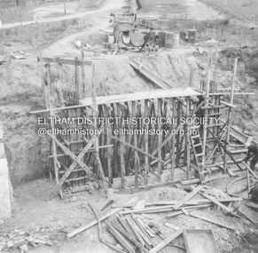
Album - Photograph, J.A. McDonald, Dixons Creek Road, June 1957
Dixons Creek Road Bridge over Dixons Creek – 56FD330 June 1957 Dixons Creek pier forming columns and beam Advertising (1957, January 19). The Argus (Melbourne, Vic. : 1848 - 1957), p. 33 (Col. 9). Retrieved August 24, 2022, from http://nla.gov.au/nla.news-article71777065 SHIRE OF ELTHAM. Loan No. 27.-Notice of Intention to Borrow Sum of £ 15,000 for Permanent Works and Undertakings. - Notice is hereby given, that the Council of the Shire of Eltham proposes to borrow the sum of £15,000 on the credit of the municipal revenues of the president, councillors, and ratepayers for the said shire, such sum to be raised by the Issue of debentures in accordance with the provisions of the Local Government Acts. 1. Maximum rate of interest that may be paid is £5/10/ per cent, per annum. 2. The purposes for which the loan is to be applied are: Construction of Sanitary Conveniences at Shire Office, Council's contribution towards costs of Dixons Creek Bridge, Construction of Mt. Pleasant rd., Construction of Cherry Tree rd. 3. The period of the loan shall be 10 years. 4. Moneys borrowed will be repayable by providing out of the Municipal Fund twenty half-yearly instalments of approximately £985/1/6 each, including principal and interest on the first day of October and the first day of April during the currency of the loan. The first Instalment shall be payable on the first day of October 1957. 5. Such moneys shall be repayable at the Commercial Bank of Australia Limited, Melbourne, or at the Council's bankers for the time being in Melbourne. The plans and specifications and the estimates of the costs of the proposed works and a statement showing the proposed expenditure of the moneys to be borrowed are open for inspection at the Shire Office, Eltham. R. J. HAM. Shire Secretary.Record of various Shire of Eltham infrastructure works undertaken during the period of 1952-1962 involving bridge and road reconstruction projects, sometimes with Eltham Shire Council Project Reference numbers quoted. It was during this period that a number of significant improvements were made to roads and new bridges constructed within the shire that remain in place as of present day (2022). In many situations, the photos provide a tangible visible record of infrastructure that existed throughout the early days of the Shire. The album was put together by or under the direction of the Shire Engineer, J.A. McDonald.infrastructure, road construction, shire of eltham, bridge construction, dixons creek bridge, dixon's creek road, 1957-06 -
 Bendigo Military Museum
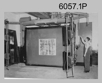
Photograph - Photographic Technicians performing tasks at the Army Headquarters Survey Regiment, c1960s
These eight photographs were most likely taken in the 1960s in Lithographic Squadron at the Army Headquarters Survey Regiment, Fortuna, Bendigo. Although Photo .1P is not annotated the remainder have the name of the technicians written on the back. The equipment operated by the technicians is the KLIMCH Commodore camera. The main tasks undertaken by the technicians were most likely enlargements and reductions of map reproduction material. The KLIMSCH Commodore camera was introduced in 1953 and was the largest in the Southern Hemisphere. It was replaced with a new model of the same size in 1979. The new model with its computer-based interface provided productivity gains with improved speed and its consistent results led to less wastage in time and materials. Its variomat lens system provided improved retention of map feature linear weights during the camera reduction process. The typed description pasted on the back of photo .5P states “Cpl R. MacKenzie of Bentley, Perth (WA) of the AHQ Survey Regt, located at “Fortuna”, Bendigo, (Vic). Has been in the Army for 5 years. He removes the lens cap from the 70 inch F16 lens of the giant KLIMSCH camera used in map making for the Army. The camera which was specially made for the Army in Germany is fully automatic and power operated. It is claimed to be one of the biggest automatic cameras of its type in the world. It was made to the specifications of the Aust Army Survey Corps to assist in the production of the very high standard maps for the Army. The AHQ Survey Regt also assists Commonwealth and other Govt departments in the printing of maps required other than for Army needs. The KLIMSCH camera is used for cartographic mapping photography.” This is a set of photographs of technicians operating photographic reproduction equipment at the Army Headquarters Survey Regiment, Bendigo c1960s. The photographs were printed on photographic paper and are part of the Army Survey Regiment’s Collection. The photographs were scanned at 300 dpi. .1) - Photo, black & white, c1960s, Les ‘Snow’ Taylor, Lithographic Squadron .2) - Photo, black & white, c1960s, Les ‘Snow’ Taylor, Lithographic Squadron .3) - Photo, black & white, c1960s, John Rolfe, Lithographic Squadron .4) - Photo, black & white, c1960s, John Rolfe, Lithographic Squadron .5) - Photo, black & white, c1960s, CPL R. MacKenzie, Lithographic Squadron .6) - Photo, black & white, c1960s, unidentified, Lithographic Squadron .7) - Photo, black & white, c1960s, George Graham, Lithographic Squadron .8) - Photo, black & white, c1960s, L to R: Bill Snelson, George Graham, Lithographic Squadron.1P – no annotation .2 to .4 – personnel names (less rank) annotated on back. .5 – name and rank annotated on back, with detailed typed description .6 to .8 – personnel names (less rank) annotated on back. royal australian survey corps, rasvy, army survey regiment, army svy regt, fortuna, asr, litho -
 Wodonga & District Historical Society Inc
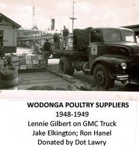
Photograph - Wodonga Poultry Suppliers, Late 1940s
Wodonga Poultry Suppliers was established in the late 1940s by Albert (Bert) Elkington in partnership with his father-in-law Artie Phillips and Aubrey Gilbert. From the beginning they had an eye on the export market. Artie (Arthur) Phillips sold Bert and Aubrey the land and became the third partner. In 1945 Aubrey and Bert each gained a repatriation loan and scored £500. They cleared the land, made the bricks by hand, built freezers and killing pens and started killing and selling to the local trade. By 1947 they had completed the first large freezer, packing room and killing sheds all to the specifications of the Department of Primary Industry. They gained an export licence and began exports to England under the brand name “Donga”. By 1950, 120,000 poultry and 50,000 pairs of rabbits annually left the Athol St, Wodonga premises for overseas markets. Unfortunately the business was adversely impacted by the English wharf strike, with large stock losses and changes to the English poultry trade. Wodonga Poultry Suppliers made changes to the plant to cater for meat export to the ready markets of England, Greece, the Persian Gulf and Japan. By the 1962, Wodonga Poultry Suppliers were exporting poultry, rabbits, hares, lamb, mutton, pie offal and quarter beef to the UK, mutton to Greece and veal sides to Bahrain. The business had outgrown the original works in Athol St and larger and improved facilities were needed. Donga Meats Pty Ltd was set up in October 1963. In 1967 Bert Elkington sold his share of the company to Consolidated Meat Holdings and came back for a time as a stock controller. He passed away in Wodonga in 1993. These images are significant because they document an early major export industry established in Wodonga, Victoria. A collection of images documenting production at the Wodonga Poultry Suppliers premises in the late 1940s.wodonga poultry suppliers, early wodonga businesses, bert elkington -
 Melbourne Tram Museum
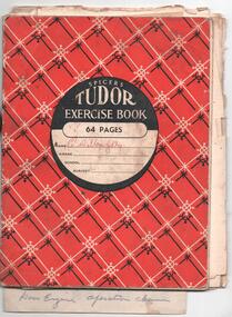
Document - Notebook, Charlie Willoughby, personal notes on tramcar maintenance, operations, recovery etc of C. Willoughby, late 1950's to early 1960's
Exercise book with personal notes on tramcar maintenance, operations, recovery etc of C. Willoughby in a Spicers Tudor Exercise book - 64 pages with arithmetical tables on the rear cover. Topics covered: Rail Grinder - details on how to operate and maintain it North Fitzroy Dick Kerr, Clyde, K35 and RC2 Controller sequences and diagrams - notes on testing and faults Buzzer wiring diagrams Maintenance of trams interiors and rooves - items to be checked for Line Breakers Lighting Circuits Compressors Trolley poles etc Air operated doors Re-railing of Maximum Traction trams - 22E ditto for equal wheel bogies ditto when split points Use of false trucks Derailments on the Royal Park line Electrical equipment faults Adjusting Trolley Poles heights and tension Notes on truck types and braking Brake diagram summary, giving specifications and a list of relevant drawings Forms for the insulation testing of the Rail Grinders Checking motor leads and electrical equipment - written on the rear of a St Patrick's Day Procession notice for 1962. Advice from Neil Elfick, 23/6/2018 knew him when the Running Shed Foreman at Kew Depot.trams, tramways, tramcars, faults, controllers, 22e trucks, derailments, accidents, royal park, grinder, notices and information, st patricks day -
 Melbourne Tram Museum
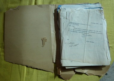
Letter - Correspondence, Melbourne & Metropolitan Tramways Board (MMTB), "Trolley Buses", 1922-36
File containing correspondence between the MMTB Chief Engineer Mr. Strickland and various companies, including Railless Ltd, Australian General Electric, English Electric / Dick Kerr and its UK consultants Heap and Digby (H&D) between the period August 1922 and August 1936. Includes drawings, technical specifications, some of which are duplicated in the Reg Item 535 file. For a listing of the contents of this file and of Reg Item 535, see Related Documents - htd535-536list.pdf Item 536 - Trolley Buses Listed from top of file, in order found. Letters generally to/from MMTB Chief Engineer. Date Type Notes 7/8/1936 Letter from TE Barnes – re Bremen Germany Steam Omnibus. Three pages. On foolscap paper – rest quarto. Has been damaged. 3/2/1926 Letter from Bruce Henderson re transport in the Glen Eira Rd area – poor private bus. 25/10/1925 Letter to G. Higgins, regarding a paper he had presented and printed in Australian Municipal Journal about transport around Melbourne, predicted the demise of trams, trains. Notes Spencer St bridge. Copy of paper is pinned with letters. 28/819/22 Copy of letter to H&D from AEC (see above) Includes the Mexborough test gradient drawing. Undated Pamphlet from Railless Limited about Birmingham’s new trolley buses. 16/3/1923 Extract from Electric Railway and Tramway Journal – wages of trolleybus drivers not getting paid extra in Bradford. Two copies pinned together. 9/4/1923 Letter from H&D re pamphlet exchange You should have had it! 23/2/1923 Letter to H&D asking for information. Has a note re the Board’s attitude towards motor buses. 28/8/1922 to 24/23 Series of letters pinned together with L. de Koenneritz regard trolley buses and Paris. Noted that the MMTB did not have the legislative power to run trolley buses. 15/2/1922 to 10/4/23 Series of letters pinned together with the Aust. GE regarding trolley buses and references to their operation in journals. 10/1/1923 Letter from H&D re request for information on driving gear of Railless Ltd. vehicles 23/2/1923 Letter to H&D re above. 23/2/1923 Sheet of paper on “Steads Review” paper – pamphlet not yet to hand. 8/11/1922 to 10/1/1923 Series of letters with H&D pinned together asking for Railless driving gear – reluctant to provide. 26/9/1922 Letter from H&D, with copy of letter from English Electric enclosing materials regarding Trolley Bus equipment. Note much of this material is the same as that in Reg Item 535 contained within the green cloth tape. Performance curves for DK 26B motor Blueprint – 4449 – outline of controller DK, Type D, form B. Specification for DK 26B trolley motor. Blueprint – drawing 2810 – DK 26 Motor Blueprint – No. 1312D – controller diagram Pamphlet – EE – tramcar Type D automatic circuit Breakers. Publication No. 230, dated 9/1920. Ditto, Form A, drawings No 3565, 1/1/19. Performance curves for DK85A motor Blueprint – P2002M034 – DK85 Motor. EE specification for Traction Motor DK85 Modified from a tram motor. Blueprint – EE drawing – P2002M036 – DK85 motor with ball bearings. EE blueprint P2102F021, traction control wiring for form D controller. EE blueprint P2103F033 – outline of controller type SE1, form C and D. EE blueprint P2102Z011 – wiring diagram for type SE1 form controller. EE blueprint – P2102F025 – diagram of connections (wiring) for Type SE1, form D controller.trams, tramways, trolley buses, melbourne, mmtb, aec, heap and digby, english electric, railless, dick kerr, general electric -
 Trafalgar Holden Museum
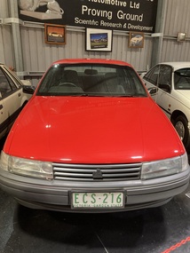
Vehicle - VN Commodore, 1988
The VN Commodore was available in Executive, S, SS, Berlina and Calais specification levels, although a more basic SL model (opt. code A9K) was supposedly offered to government and fleet buyers, as it was not officially listed as part of the Commodore range. Changes in the relative values of the Australian dollar, the Japanese yen, and the US dollar made it impractical to continue with the well-regarded Nissan engine of the VL. Instead, Holden manufactured their own 90-degree V6 based on an old Buick design from the US, although initially it was imported. The 5.0-litre V8 remained optional and received a power boost to 165 kW (221 hp). Both these engines used multi point GM EFI and the V6 using 3 coil-packs for ignition. Holden and HSV developed this car as the basis for racing in Group A Confederation of Australian Motor Sport events. While the minimum number of cars built to qualify in Australian Touring car Championships, with modified body kit, brakes or engine is 500, only 302 VN were built but CAMS granted an exemption allowing them to compete.Holden and HSV had worked hard to develop this car to be a serious competitor to the Skyline, Ford Sierra and the BMW which had dominated in the previous years. This was to be the Holden’s answer and coincided with the return of Peter Brock back to the Holden team from 1987.Mechanically the cars were fitted with reworked version of Holden’s 4.9 litre V8. The engine block was cast for additional strength, modified cylinder heads roller rockers and high fuel flow fuel injection was applied. Output was 215 kw at 5200revs and, though at today’s standard, that is not that much it was very impressive at that time. The drive was through a six speed ZF gearbox with a heavy duty racing clutch and a limited slip differential.Under the Hawke government's Button car plan, which saw a reduction in the number of models manufactured locally, and the introduction of model sharing, the VN Commodore was rebadged as the Toyota Lexcen, named after the late America's Cup yacht designer, Ben Lexcen. Subsequently, the Toyota Corolla and Camry were, similarly, badged as the Holden Nova and Holden Apollo.Red executive 4 door sedanHolden Lion and stone emblem grille centre, Commodore boot LHS, Lion and stone emblem boot RHS.vehicle, vn commodore, holden, car -
 Melbourne Tram Museum
Legal record, Melbourne & Metropolitan Tramways Board (MMTB), "Agreement Melbourne and Metropolitan Tramways Board with A.N. Colquhoun", May. 1948
Bound Document, two large ruled grey folded sheets with containing various schedules and letters typed onto foolscap (folio) or quarto sheets. Titled "Agreement Melbourne and Metropolitan Tramways Board with A.N. Colquhoun "signed and sealed on 18th May 1945. Bound on left hand side with green ribbon. Gave Archibald Norman Colquhoun the right to advertising on the inside of tramcars and buses and on the rear of tickets for five years. Gave details of the contract, minimum payments, rebates and conditions of the contract. Schedule A - two pages - space available in tramcars Schedule B - two pages - buses ditto Schedule C - passenger check tickets / annum - some 350million - one page Schedule D - actual tendered document, 15/4/1948 - one page Schedule E - the Specification for the tender - five pages Schedule F - Letter signed by A.N. Colquhoun, on The Reilly Advertising Co. letterhead of which has was the Managing Director giving his credentials. Schedule G - supporting letter on The Reilly Advertising Co letterhead. Schedule H - Letter from the Commercial Bank of Australia Ltd - supporting Mr A.N. Colquhoun. Schedule I - letter from MMTB advising A.N. Colquhoun of his successful bid. Schedule J - Draft agreement in tender document - five pages - signed 15/4/1948."996/7" in top left hand corner of document and stamped "Treasurer"trams, tramways, tickets, advertisements, tramcars, buses, contracts, legal agreements -
 Wodonga & District Historical Society Inc
Photograph - Codling Collection 01 - Woodland Grove, Wodonga
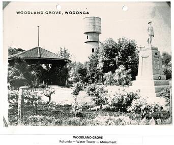
Miss Olive Codling was a Foundation Member and a Life Member of the Wodonga Historical Society. Many of her prize-winning photos are held in the Society Collection. She also held a range of roles and committee positions in a wide range of Wodonga community organisations. These included the Horticultural Society, the Wodonga Arts Council, the Wodonga Camera Club and the Wodonga Lapidary Club. Woodland Grove is located in the triangular reserve at the corner of High and Hovell Streets, Wodonga. ‘Woodland Grove". It was named in honour of John Woodland at the same time as the opening of the band rotunda in September 1920. John Woodland, Wodonga Shire’s first president, was born in Kent, England, in 1829 and came to Sydney with his parents in 1839. He arrived in the Wodonga district about 1853, where he created a successful carrier's business. He first lived on the Old Barnawartha Estate and a few years later purchased land at Green Hills, Wodonga West, where he farmed and also ran a hotel. The hotel licence was relinquished to give attention to duties as secretary and clerk of works to Wodonga Shire, which was then the Wodonga Riding of the Shire of Yackandandah. He was a main agitator for the separation of Wodonga district from Yackandandah Shire. This was successful in 1876, and he became the first president of Wodonga Shire. He held this post for two years, then taking on the role of shire secretary in 1878 until 1913. He concurrently undertook the role of clerk of works (engineer) from 1896 to 1907. As clerk of works he prepared the plans and specifications for, and supervised the construction of the big bridges on the Albury road and at Bonegilla and other important works. In his mid 70s, he proffered his resignation on a number of occasions but it was not accepted. Despite physical weakness and impaired vision, John continued his duties to the end, with the help of his daughter Rose Murphy. Rose became shire secretary for 20 years after her father’s death in 1913.This photo collection is significant as it documents the naming of a public area in Wodonga to honour an original and long-serving member of the Wodonga Shire Council.A black and white photo of Woodland Grove in High Street, Wodonga. It includes the rotunda, the water tower and the soldier's memorial. There is a post and wire fence in the foreground as well as several trees and rose bushes. Beneath the photo: "WOODLAND GROVE / Rotunda - Water Tower - Memorial"high st wodonga, woodland grove, john woodland -
 Bendigo Military Museum
Plaque - Mounted Klimsch Commodore Cartographic Camera Lenses, WYCOMBE Constructions Pty Ltd, 1997
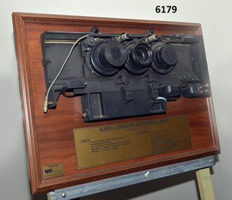
These are the Lenses from the Klimsch Commodore Cartographic Camera that was located in Lithographic Squadron at the Army Survey Regiment, Fortuna, Bendigo. The KLIMSCH Commodore camera was originally introduced to the Survey Regiment in 1953 and was the largest in the Southern Hemisphere. It was replaced with a new model of the same size in 1977. These lenses are from this new model. The new model with its computer-based interface provided productivity gains with improved speed and its consistent results led to less wastage in time and materials. Its variomat lens system provided improved retention of map feature linear weights during the camera reduction process. The camera which was specially made for the Australian Army in Germany was fully automatic and power operated. It was claimed to be one of the biggest automatic cameras of its type in the world. It was made to the specifications of the Royal Australian Army Survey Corps to assist in the production of the very high standard maps for the Australian Army. THIS KLIMSCH COMMODORE CARTOGRAPHIC CAMERA was in operation 1977 - 1997". It was a Precision Darkroom Camera especially suited for Cartographic Reproduction of Line, Continous Tone, Halftone and Colour Separation. Reproduction of Negatives and Positives from a variety of Reflection or Transmission Originals. Its characteristics were: Maximum Negative Size 1.27m sq, Copy Holder (Vacuum) 2m sq, Maximum Enlargement 400%, Maximum Reduction 13%, Automatic 60, 90 and 120cm Focal Length Lens, Transmission or Reflection Originals, Pulsed Xenon, Photo Flood or Fluorescent Tube Light Source, Maximum Reflection Original 1.3m x 1.85m, Maximum Transmission Original 1.3m x 1.85m, Exposure Light Monitoring System." The camera was superseded by computerized image manipulation software associated with the Automap system. These significant and extremely high-quality Lenses were retrieved by WYCOMBE Constructions Pty Ltd during the demolishment of the camera in 1997 and then mounted on a display board. See also Item 6189.4P for more photographs of the camera.Lenses from the Klimsch Commodore Cartographic Camera mounted on a very heavy timber display board. The display board contains an engraved plate that describes the technical characteristics of the camera."KLIMSCH COMMODORE CARTOGRAPHIC CAMERA 1977 - 1997", "FUNCTION: Precision Darkroom Camera especially suited for Cartographic Reproduction of Line, Continous Tone, Halftone and Colour Separation. Reproduction of Negatives and Positives from a variety of Reflection or Transmission Originals." "CHARACTERISTICS: Maximum Neg Size 1.27m sq, Copy Holder 2m sq, Maximum Enlargement 400%, Maximum Reduction 13%, Automatic 60, 90, 120cm Focal Length Lens, Transmission or Reflection Originals, Pulsed Xenon, Photo Flood or Fluorescent Tube Light Source, Maximum Reflection Original 1.3m x 1.85m, Maximum Transmission Original 1.3m x 1.85m, Exposure Light Monitoring System." royal australian survey corps, rasvy, fortuna, army survey regiment, army svy regt, asr, litho -
 Working Heritage Crown Land Collection
Award - Royal Mint Building Award, JA Dodd Excellence in Construction
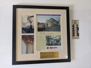
2002 Excellence in Construction AwardsFramed Award 2002 Excellence in Construction Awards, JA Dodd LTD, Excellence in Construction, (Existing Buildings) Under $2 million, Project: The Royal Mint Building, Architect: Robert Peck von Hartel Trethowan, Location: 280 William Street Melbourne, J A Dodd Ltd's refurbishment of the historic former Royal Mint Building delivered to the client's specification in retaining the features of this historic building, while at the same time providing modern office accommodation with state of the art facilities. New works have been defined by a modern style encompassing glass, stainless steel and flush surfaces, offering a stark departure from the ornate finishes of the original building. Traditional timber mouldings, tiles stonework and intricate paint methods have been used only where repairs to the existing building were required. The judges praised the superb job and made special mention of the exposed roof trusses. 38 master builder awards -
 Bendigo Military Museum
Map - Map Extract - Charterhouse of Mendip, John James Raisbeck, Unknown
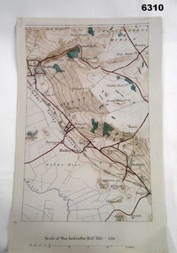
Map extract showing the towns of Cheddar, Rodney Stoke, Westbury and a smaller town of Easton. The area depicted is part of Somerset, England. Map is hand drawn by J.J. Raisbeck date unknown. John James RAISBECK was born on 4 July 1880 at Christchurch New Zealand. He served 4 years (Citizen Military Force - CMF) in 9th Australian Light Horse Regiment in Central VIC with the rank 2nd Lieutenant. He was the first Australian appointed to the Survey Section RAE, on 16 April 1910, as a draughtsman which was his civilian profession, with the rank Warrant Officer, honorary 2nd Lieutenant. He was required to resign his commission in the CMF. He supervised the draughting work of the Section in Melbourne and was largely responsible for the mapping standards and specifications set in the production of the Cowes one-inch-to-one-mile military map, which became the enduring Australian standard. He was also responsible for supervising the printing of the maps by the Victorian Government Printer. He was appointed 2nd Lieutenant in the AIF Survey Corps draft on 6 December 1917 (from Melbourne) embarking for England on 22 December 17. He was attached to the Australian Corps Topographic Section in France from 21 April 1918 to 5 March 1919 serving as Second-in-Command and as Officer Commanding. He was promoted Lieutenant 15 October 1918, attending the AIF Survey School, Southampton in 1919, returning to Australia 23 June 1919, before his AIF appointment was terminated 17 July 1919. He went on to serve the Survey Section RAE and Australian Survey Corps, including in the Second World War, having been promoted Captain then Major and Officer Commanding Army Headquarters Cartographic Section until February 1940. He retired after 33 years of service to military survey, and after serving the Corps in two world wars, on 4 July 1943 with the retired rank Lieutenant-Colonel. He was the author of the article ‘A Short History of the Military Survey of Australia, 1907-1936’, published in The Australian Surveyor, Sept 1, 1937Map extract slightly larger than A4. Scale: One Inch to One and a half Mile. 1:31680, 9 x copiesSignature of "J.J. Raisbeck" bottom right-hand cornerroyal australian survey corps, rasvy, fortuna, army survey regiment, army svy regt, asr