Showing 71 items
matching ignition
-
 Puffing Billy Railway
Lister Auto Truck
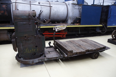
The Lister Auto-Truck was a small monowheel tractor built for moving light loads around factories, railway yards and similar sites. They were built by R A Lister and Company of Dursley, Gloucestershire, well known for their range of small stationary engines The Auto-Truck was one of several monowheel tractors to appear in the 1920s and '30s, with the availability of small, reliable petrol engines, as developed for motorcycles and the stationary engines for which Lister were already known. These were tricycle vehicles, with the single leading wheel used for both drive and steering. Their simple construction carried most of the mechanism on this wheel as a single unit, the chassis with the trailing wheels being little more than a trailer for balance. Simplicity was a key feature. The engines were single-cylinder and air-cooled. Ignition was by magneto, rather than requiring a battery and electrical system. One of these designs was produced in the 1920s by George Grist of the Auto Mower Co., Norton St Philip, Somerset. The engine was a JAP 600 cc four-stroke air-cooled sidevalve, a typical small engine of the time. The Auto Mower Co. were Lister agents and when Lister heard of this 'Auto-Truck' they bought one for use in their own factory. It was used to carry heavy engine castings from the foundry to the machine shop. Lister customers saw them and there was such interest in wanting to buy them that Lister negotiated with Auto Mower to build them under licence. Although Lister were already well known for their small petrol stationary engines, these were heavy cast-iron engines with water hopper cooling and unsuitable for vehicle use. Lister remained with the JAP engine for the Auto-Truck. The Auto-Truck was designed for use in factories or other places with smooth surfaces of concrete or tarmac. This allowed the use of small solid-tyred wheels with only simple suspension, making the vehicle simple, cheap and lightweight. They had little ability on soft surfaces though and could even topple over if driven carelessly across slopes. Their design was a compromise between the top-heavy nature of the tall engine grouping above its wheel and a well thought-out chassis for stability. The bearing between them was a large diameter ring roller bearing, mounted at the lowest part of the chassis. This gave rigidity and stability, even after long wear. A ring of rolled channel girder was attached to the engine group and rollers on the chassis carried the load upon this. On early Auto-Trucks this bearing is set very low, in line with the chassis members, and is covered by thin steel plates. The front panel of the engine cover is distinctive with large ventilation holes and a Lister signature cut through it. Strangely this panel is made of thick cast iron, providing substantial weight high on the engine and only adding to its top heaviness. To improve visibility of moving vehicles in noisy factories, this panel was often painted white, the rest of the vehicle being Lister's usual brunswick green. The driver was seated on a Brooks bicycle saddle, which in recognition of the lack of vehicle suspension, was carried on the end of a cantilevered bar that acted as a leaf spring. A wide handlebar on the engine group was used for steering. A squeeze bar the width of this handlebar engaged the clutch. Controls included a hand throttle, a gear lever with two forward and one reverse gears, and a large handbrake lever. The engine unit rotated freely for a full 360° rotation. When used in reverse, the Auto-Truck could either be driven from the saddle, looking backwards over the driver's shoulder; or they could dismount, swivel the engine unit around and control it as a pedestrian-controlled truck from behind. Under the engine cover were two equal diameter tanks, a fuel tank for petrol and a shorter oil tank. Engine and chain-drive lubrication used a total-loss oil system, controlled by a small pump and needle valve. Info Ref: Lister Auto-Truck - Wikipedia https://en.wikipedia.org/wiki/Lister_Auto-TruckHistoric - Industrial monowheel tractor for moving light loads around factories, railway yards and similar sites.The Lister Auto-Truck - small monowheel tractor Made of steel with three wheels. Powered by a J.A.P single cylinder petrol motor which is Hand Cranked to start.Lister puffing billy, lister, lister auto truck, monowheel tractor -
 Moorabbin Air Museum
Document (item) - Ignition Systems Training Notes RAAF School of Technical Training Wagga
-
Whitehorse Historical Society Inc.
Article, Thornton Crescent, 1996
Article on businesses in Thornton Crescent, MitchamArticle on businesses in Thornton Crescent, MitchamArticle on businesses in Thornton Crescent, Mitchamthornton crescent, mitcham, mitcham automatics, performance ignition services, wonga concrete, link automotive, timbermate products pty ltd, haulaway, pelikan trading company pty ltd, motafit service centres, graphi-cal melbourne -
Moorabbin Air Museum
Document (Item) - High energy ignition unit Rotax NB38, Rocket interceptor, CA-31, CA-23, All weather fighter, GAF all through jet trainer, Air superiority fighter, Rotax, Arrow engines, Kitplane magazine, CAC formulae, data testing, engine testing log of aircraft incidents 1942 to 1957, Australian aircraft components, A3J-1 jet fighter, Ceres, primary jet trainer, Wallaby, CA 31, Mirage III, Jindivik, Ikara, Canberra, Nomad, Military projects, list of managers , Avon 100 series, anti icing, propeller design, gas turbine part 1 and 2, Canberra modification 750, 746, CAC Keith Meggs collection post WW2
-
 Queenscliffe Maritime Museum
Equipment - Rescue Equipment
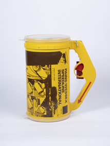
The line throwing apparatus has been in use for several centuries, in a wide variety of forms. It initially started off as manually launched lines that had shorter ranges and were not very accurate. They faced problems on wind-powered boats and ships since they were dependent on wind speed, wind direction, and the operator accuracy.Modern-day line throwing apparatus are powered using rockets, pneumatic systems, or slingshot mechanisms. They fall under two main categories of propulsion- pyrotechnic, and pneumatic. Pyrotechnic systems make use of an ignition that is used to launch the line, whereas pneumatic systems make use of built-up pressure. Pyrotechnic systems are volatile and can be extremely dangerous due to accidental ignition. In response to growing concerns about the safety of pyrotechnic systems, pneumatic based launchers were invented and widely implemented in the late 20th century.Yellow line throwing device consisting of a canaster containing rolled rope and a firing mechanismPains-Wessex Speedline International. Pt No 5151-01/02speed line, line throwing, marine rescue, pyrotechnics -
 Department of Energy, Environment and Climate Action
CSIRO Incendiary Machine
Alan McArthur from the CSIRO began his experimental burning program in the late 1950s near Canberra and published his landmark paper in 1962, “Controlled burning in eucalypt forests”. Leaflet No. 80, as it was known, proved a turning point for forest and fire managers across Australia. It led to the McArthur Forest Fire Danger Meter (FFDM) which first appeared in operational use in 1967 as the Mk 4. The CSIRO had developed its semi-automatic aerial incendiary machine dropping small capsules, with the first trial from a fixed-wing Cessna 337 at Manjimup in December 1965. In April 1969, the Forests Commission borrowed the second prototype of the CSIRO machine to carry out fuel reduction burning at Orbost. The success prompted the purchase of their own machine in 1970, which now sits in the Altona Museum. Pioneering machine in the development of aerial ignition in AustraliaAerial Incendiary Machineforests commission victoria (fcv), planned burning, bushfire aviation, bushfire -
Moorabbin Air Museum
Document (Item) - (SP) Technical Orders - multitude - list in "Context"
Possibly related to navigationtechnical order an 03-10abb-163 cyl plug selector valve assy overhaul with parts breakdown, technical order an 03-5-308 switch pressure actuated overhaul with parts breakdown, technical order an 05-55a-13 d-c selsyn position indicators and transmitters, technical order an-03-10abb-237 swing check valve overhaul with parts breakdown, technical order to-00-20a-2 airplane maintenance forms, technical order to-01-1-390 food and galley equipment responsibility, technical order to-01-1-515 rework solenoid control head part 966129, technical order to-01-1-619 oxygen regulators inspection and replacement, technical order to-02-10ab-1 r985 aircraft engines operations, technical order to-03-1-6 solenoid meshing devices ops service overhaul, technical order to-06-1-8 fuels and lubricants, technical order to-06-10-1 lubrication oils grades and use, technical order to-08-5-10 radio scr-578-a defective reels rl-48, technical order to-1-1-383 removal of ammunition from aircraft, technical order to-10-25-3 film developer assy operations servicing parts catalog, technical order to-14s3-1-503 inspection of life raft co2 cylinders, technical order to-15a1-2-12-3 air pressure regulator overhaul, technical order to-15h4-2-2-3 ignition units overhaul, technical order to-15h6-2-2-123 cockpit temperature control box, technical order to-15h6-2-2-13 cockpit temperature control box, technical order to-15h6-2-2-163 cockpit temperature control box overhaul, technical order to-1f-1-525 safety wirting pilot oxygen shutoff valve, technical order to-1f-86-210 sabre electrical connector for test equipment, technical order to-2r-0470-12 an 02a-40eb-2 aircraft engines service, technical order to-2r-0470-13 an 02a-40eb-3 aircraft engines overhaul, technical order to-2r-0470-14 an 02a-40eb-4 aircraft engines parts breakdown, technical order to-4s-1-2 high pressure air valve cores, technical order to-4s5-2-3 tail skid shock struts overhaul, technical order to-5f4-3-3 true airspeed signal control amplifier overhaul, technical order to-6j13-2-1-501 dual float switch assy installation, technical order to-6j14-1-5 torque values self sealing bladder cell multi bolt fittings, technical order to-6j3-4-15-4a vs-2 fuel regulator parts breakdown, technical order to-6j5-15-3 fuel filetr assy overhaul, technical order to-6j5-15-4 fuel filter assy parts breakdown, technical order to-6j5-18-3 micronic filters overhaul, technical order to-6j5-18-4 micronic filters parts breakdown, technical order to-6j5-24-3 av fuel filter replaceable micronic element, technical order to-6j5-5-3 fuel filter 03s12166d overhaul with parts breakdown, technical order to-6r-1-2 engine carburetor installation, technical order to-6r1-3-1-35 bendix injector carburetor overhaul, technical order to-6r9-2-11-3 valve check overhaul with parts breakdown, technical order to-6r9-2-12-3 swing check valve overhaul with parts breakdown, technical order to-6r9-2-14-3 check valve flow indicator overhaul wth parts breakdown, technical order to-8a6-3-3-3 ac generator overhaul, technical order to-8a6-8-4-4 engine driven aircraft generator parts breakdown, technical order to-8a6-9-3-3 aircraft ac generator overhaul, technical order to-8d1-21-3-33 fractional horsepower motor 5ba25aj28b overhaul with parts breakdown, technical order to-8d1-21-3-33 fractional horsepower motor 5ba25mj426b overhaul with parts breakdown, technical order to-8d1-29-2-3 direct current motor parts breakdown, technical order to-8d1-9-13-23 oil cooler flap control overhaul parts breakdown, technical order to-8d1-9-19-3 direct current motor overhaul with parts breakdown, technical order to-8d1-9-21-3 electromechanical linear actuator overhaul, technical order to-8d1-9-21-4 electromechanical linear actuator parts breakdown, technical order to-8d1-9-22-3 electromechanical power unit overhaul, technical order to-8d1-9-22-4 electromechanical power unit parts breakdown, technical order to-8d3-8-6-3 position light flasher overhaul, technical order to-8d6-5-4-504 mod westinghouse generator a45j247, technical order to-8e2-5-2-13 aircraft magnetos overhaul, technical order to-8e2-5-2-14 aircraft magnetos parts breakdown, technical order to-8ri-3-5-3 generator field control relay m-2 overhaul, technical order to-9h4-2-24-4a stratopower hydraulic pump parts breakdown -
 Moorabbin Air Museum
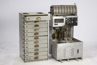
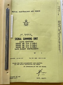
Manual (Item) - (SP) AAP 7444.005-3M Signal Summing Unit Auto Ignition C74406-4 5 and 6 Safe Flight Instrument
-
Moorabbin Air Museum
Manual (item) - CAC cylinders wiring ignition oil pump sump propeller shaft reduction gears crankshaft, CAC Pratt and Whitney wasp engine drawings R-1830 82 and 92
-
Moorabbin Air Museum
Book - A Text Book on Aviation Volume 3 Engines, Ignition, Carburation, Diesel Engine Supplement, Leslie Thorpe
-
Moorabbin Air Museum
Manual - Griffon Engines, Maintenance Notes Griffon Mk 74 Engine ( As Fitted to Firefly Mk 4,5 & 6 Aircraft )
Maintenance instructions for Griffon Mk 74 engine, as fitted to Firefly.Photocopies in blue manila walletnon-fictionMaintenance instructions for Griffon Mk 74 engine, as fitted to Firefly.crankshaft & connecting rods, pistons & rings, crankcase & reduction gear, cylinder block & camshaft assembly, sumps, wheelcase, supercharger, valve & ignition timing, oil system, auxiliary gear box