Showing 246 items matching "engine parts"
-
 Flagstaff Hill Maritime Museum and Village
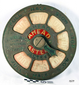
Equipment - Ship's Telegraph section, A. Robinson & Co. Ltd, Late-19th to mid-20th centuries
The ship’s communication system that was used from the late 19th century to early-to-mid-20th-century is called an Engine Order Telegraph (E.O.T.) or ship’s telegraph. The system has two parts, the Bridge Section and the Engine Room Section. The Bridge Section is usually mounted on top of a pedestal, and the Engine Room Section is often attached to a vertical surface. The standard commands printed or stamped onto the dial are the directions of AHEAD and ASTERN, and the speeds of STOP, SLOW, HALF, and FULL. The ship’s pilot on the Bridge of a vessel sends his Orders for speed and direction to the to the Engine Room with the E.O.T. He moves the lever or levers, depending on the number of engines the ship has, to change the indicator on the Bridge Section’s dial to point in the new direction and speed of travel. This change causes the Orders to be duplicated on the Engine Room Section’s dial and a bell to signal the change at the same time. The engineer then adjusts the ship’s engines and steering equipment to follow the pilot’s Order. The manufacturer, A. Robinson & Co. Ltd of Liverpool, established his business in 1780 and continued until 1968 when the business was purchased by marine products maker Chadburns, established in London in 1870.This Engine Room section is part of a ship's telegraph communication system and represents marine technology used in the late-19th to mid-20th-century. Engine Room Section of a ship’s telegraph or Engine Order Telegraph (E.O.T.). The round brass dial has inscriptions stamped around its edge and centre. Red inlaid glass plates have inscriptions in white paint on them. The inscriptions are nautical terms for direction and speed and include the maker’s details. A rotating pointer is joined to the centre of the dial. The maker is A. Robinson & Co. Ltd of Liverpool. Stamped: “FULL / HALF / SLOW / STOP / FULL / HALF / SLOW / STOP”, “AHEAD / ASTERN” Printed: “FULL / HALF / SLOW / STOP / FULL / HALF / SLOW / STOP” Stamped on the dial: “A. ROBINSON & CO. LTD / MANUFACTURERS / LIVERPOOL”flagstaff hill, warrnambool, maritime museum, maritime village, great ocean road, shipwreck coast, marine technology, marine communications, engine order telegraph, e.o.t., ship’s telegraph, bridge section, engine room section, ship’s engine telegraph section, marine telegraph, a. robinson & co. ltd, liverpool -
 Flagstaff Hill Maritime Museum and Village
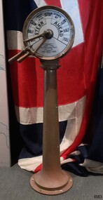
Equipment - Ship's Telegraph section, Chadburn & Sons, 1875-1898
This is the Bridge Section of a ship’s telegraph and is a Duplex Gong model, made by Chadburn & Son of Liverpool. This duplex gong model would sound two signals whenever the navigational commands were given by the ship’s pilot to change the speed or direction. The ship’s telegraph was installed on Flagstaff Hill’s exhibit of the 1909 Hobart, Tasmania, ferry “SS Rowitta” installed in 1975 and enjoyed for more than 40 years. Communication between the ship’s pilot and the engine room in the late 19th century to the mid-20th-century was made with a system called an Engine Order Telegraph (E.O.T.) or ship’s telegraph. The equipment has two parts, the Bridge Section and the Engine Room Section. The Bridge Section is usually mounted onto a pedestal, and the Engine Room Section is attached to a vertical surface. The standard marine commands are printed or stamped around the face of the dial and indicated by a pointer or arrow that is usually moved by a rotating brass section or handle. The ship’s pilot stationed on the Bridge of a vessel sends his Orders for speed and direction to the Engine Room with the E.O.T. He moves the lever or levers, depending on the number of engines the ship has, to change the indicator on the Bridge Section’s dial to point in the new direction and speed of travel. This change causes the Orders to be duplicated on the Engine Room Section’s dial and a bell or bells to signal the change at the same time. The engineer then adjusts the ship’s engines and steering equipment to follow the pilot’s Order. CHADBURN & SON, Liverpool- Chadburn Brothers, William and C.H., were joint inventors and well-established makers of optical and scientific instruments and marine gauges. The firm was granted the Prince Albert Royal Warrant in the late 19th century. In 1870 William Chadburn applied for a patent for his navigational communication device for use on ships. By 1875 Chadburn & Son was producing the brass Engine Order Telegraph in its plant at 71 Lord Street, Liverpool. In 1911 the ship RMS Titanic was launched, fitted with Chadburn & Sons E.O.T. The Chadburn Ship Telegraph Company Limited was registered in 1898 to take over Chadburn & Sons. In 1903 a large factory at Bootle, near Liverpool, and their products were being sold overseas. In 1920 electric-powered telegraphs were developed. In 1944 the name changed to Chadburn’s (Liverpool) Limited. In 1968 the company became Chadburn Bloctube Ltd. In 2000 the company, now Bloctube Marine Limited, was still manufacturing ship telegraphs. SS ROWITTA: - The 1909 steam ferry, SS Rowitta, was installed as an exhibit at Flagstaff Hill in 1975 and was enjoyed by many visitors for 40 years. Rowitta was a timber steam ferry built in Hobart in 1909 using planks of Huon and Karri wood. It was a favourite of sightseeing passengers along Tasmania’s Tamar and Derwent rivers for 30 years. Rowitta was also known as Tarkarri and Sorrento and had worked as a coastal trading vessel between Devonport and Melbourne, and Melbourne Queenscliff and Sorrento. In 1974 Rowitta was purchased by Flagstaff Hilt to convert into a representation of the Speculant, a historic and locally significant sailing ship listed on the Victorian Heritage Database. (The Speculant was built in Scotland in 1895 and traded timber between the United Kingdom and Russia. Warrnambool’s P J McGennan & Co. then bought the vessel to trade pine timber from New Zealand to Victorian ports and cargo to Melbourne. It was the largest ship registered with Warrnambool as her home port, playing a key role in the early 1900s in the Port of Warrnambool. In 1911, on her way to Melbourne, it was wrecked near Cape Otway. None of the nine crew lost their lives.) The promised funds for converting Rowitta into the Speculant were no longer available, so it was restored back to its original configuration. The vessel represented the importance of coastal traders to transport, trade and communication in Australia times before rail and motor vehicles. Sadly, in 2015 the time had come to demolish the Rowitta due to her excessive deterioration and the high cost of ongoing repairs. The vessel had given over 100 years of service and pleasure to those who knew her. This Bridge section of a ship’s Engine Order Telegraph, used with an Engine Room section, represents late-19th century change and progress in communication and navigation at sea. This type of equipment was still in use in the mid-20th century. The object is significant for its association with its maker, Chadburn & Son, of Liverpool, a well-known marine instrument maker whose work was recognised by English Royalty, and whose products were selected to supply similar equipment for use on the RMS Titanic. This ship’s telegraph is connected to the history of the Rowitta, which was a large exhibit on display at Flagstaff Hill Maritime Village from the museum’s early beginnings until the vessel’s end of life 40 years later. The display was used as an aid to maritime education. The Rowitta represents the importance of coastal traders to transport, trade and communication along the coast of Victoria, between states, and in Australia before rail and motor vehicles. The vessel was an example of a ferry built in the early 20th century that served many different roles over its lifetime of over 100 years. Bridge section of a Ship’s Telegraph or Engine Order Telegraph (E.O.T.). The round double-sided, painted glass dial is contained within a brass case behind glass. It is fitted onto an outward tapering brass pedestal with a round base. The brass indicator arrows between the handles point simultaneously to both sides of the dial when moved. An oval brass maker’s plate is attached to the top of the case. The dial’s faces have inscriptions that indicate speed and direction, and the front face and plate include the maker’s details. A serial number is stamped on the collar where the dial is fitted to the pedestal. The ship’s telegraph is a Duplex Gong model, made by Chadburn & Son of Liverpool. Dial, maker’s details: “PATENT “DUPLEX GONG” TELEGRAPH / CHADBURN & SON / TELEGRAPH WORKS / PATENTEES & MANUFACTURERS / 11 WATERLOO ROAD / LIVERPOOL” LONDON / 105 FENCHURCH STREET” “NEWCASTLE / 85 QUAY + SIDE” “GLASGOW / 69 ANDERSON QUAY” “PATENT” Dial instructions: “FULL / HALF/ SLOW / FINISHED WITH ENGINES / STOP STAND BY / SLOW / HALF / FULL / ASTERN / AHEAD” Maker’s plate: “CHADBURN / & SON / PATENT / LIVERPOOL” Serial number: “22073”flagstaff hill, warrnambool, maritime village, maritime museum, shipwreck coast, great ocean road, engine order telegraph, e.o.t., navigational instrument, communication device, ship’s telegraph, engine room section, bridge section, rms titanic, chadburn & son, chadburn brothers, william chadburn, chadburn ship telegraph company, chadburns, duplex gong, liverpool, ss rowitta, navigation, marine technology, pilot’s orders, steam power, hobart, tasmania, devonport, tasmanian-built, ferry, steam ferry, steamer, 1909, early 20th century vessel, passenger vessel, tamar trading company, launceston, george town, sorrento, tarkarri, speculant, peter mcgennan, p j mcgennan & co. port phillip ferries pty ltd, melbourne, coastal trader, timber steamer, huon, karri, freighter, supply ship, charter ferry, floating restaurant, prawn boat, lakes entrance -
 National Vietnam Veterans Museum (NVVM)
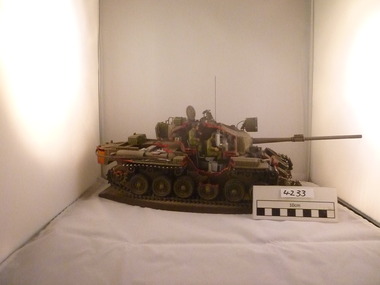
Model, Model Tank
... the vechile and its functions, various parts included the engine... the vechile and its functions, various parts included the engine ...Model Centurion Tank. Tank is painted army Green and has Red paint on edges of where surfaces are "cut away" This cut away model reveals the parts of the tank normally not seen from outside its exterior.Revealed are the men who operate the vechile and its functions, various parts included the engine /motor area.M 104model tank., centurion tank -
 National Vietnam Veterans Museum (NVVM)
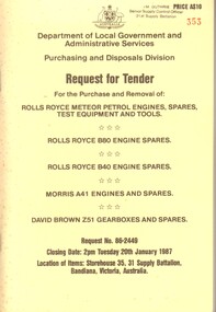
Booklet, Request for Tender for the Purchase and Removal of; Rolls Royce Meteor Petrol Engines, Spares, Test Equipment And Tools etc
Details of spare parts that were part of the Centurion Tank sale. Information Dossier for Tenders: Request No. 86-2449military equipment, request for tender -
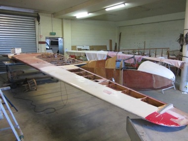 Australian Gliding Museum
Machine - Glider - Sailplane, 2012
The ES52 Kookaburra is a two seat high wing glider – sailplane of wooden construction designed by Harry Schneider and built Edmund Schneider Pty Ltd. It was first flown on 26 June 1954 and became the glider of choice for training new pilots of many gliding clubs around Australia in the 1950s, 1960s and 1970s. Several found there way to New Zealand. Further two kits were sent to Brazil and at least one of these was finished and flow successfully. The ES52 performed well with a glide ratio of about 22:1 and had soaring and cross-country capabilities. A notable feature of the ES52 design was the staggered side-by-side seating arrangement of the cockpit. This made for good in flight communication between instructor and trainee. Overall, thirty six were built by Edmund Schneider Pty Ltd. A longer wing version (the ES52B) was also introduced that had a better glide ratio (around 25:1). Five examples of this version were built. In Germany a modified ES52 was built incorporating a metal tube fuselage frame and with the addition of a engine driven propeller mounted on top of the wing which enabled the glider to be self launching. This museum collection item consists of the fuselage, tailplane, elevators, fin, rudder from the Mark I, ES 52 Kookaburra, formerly registered as VH-GFF and last owned by the Barcaldine and District Airsports Club of Queensland. The glider was in a damaged condition when it was acquired by the Museum. A decision was made by the Museum to repair the glider for display rather than endeavouring to restore it to an airworthy condition. The reconstruction of the wings is being undertaken by using parts of damaged ES 52 Kookaburra wings (as it happened from later ES 52 Marks). The Log Book for VH-GFF reveals operational life with a succession of gliding clubs around Australia. This exhibit will be of interest to gliding enthusiasts wishing to inspect the popular two seat club trainer of a by-gone era.This is a wood and fabric covered aircraft that is being rebuilt from the components of several aircraft as a non-flying exhibit.Fuselage marked with Edmund Schneider Pty Ltd Serial Number 9 and comes from the glider previously registered as VH-GFF.australian gliding, glider, sailplane, edmund schneider, es 52, kookaburra, barcaldine and district airsports club, victorian motorless flight group, alice springs gliding club, raaf richmond, raaf williamtown, gayndah gliding club, blackwater gliding club, southern downs aero and soaring club, charleville gliding club -
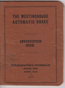 Bendigo Historical Society Inc.
Document - BADHAM COLLECTION: WESTINGHOUSE AUTOMATIC BRAKE INSTRUCTION BOOK
Brown cover book: contains details instruction of The Westinghouse Automatic Brake (64 pages). The context cover pictures demonstrations of the brake parts and operation procedures in very details.books, technical, railways, book, books, trains, railways, engines, locomotives, badham collection, collection, collections -
 Bendigo Historical Society Inc.
Document - MCCOLL, RANKIN AND STANISTREET COLLECTION: CENTRAL NAPOLEON GOLD MINING CO. N.L, 1934-1950
Pink Manilla Folder containing: General Correspondance Letters to and from suppliers of machinery and parts e.g. Electricity Supply Departments, Fred Milne & Son (Engineers), Thompsons Engineering & Pipe Co.Ltd, Miller & Co Machinery Pty Ltd, Alfred J Jorgenson, Bingle Machinery Co, The Richardson Gears Pty Ltd, Buckell & Jeffrey Pty Ltd, Commercial Union Assuarance Company Limited, Bendigo Machinery & Trading Co Pty Ltd, Ronaldson Bros & Tippett Pty Ltd (including a picture of a drawlift pump), J.G. Bloomfield, Ronaldson - Tippett list of 4583 Machines in Victoria & addfor crude oil engine, A.H McDonald & Co Pty Ltd & ad for crude oil engine, E Treliving letter & list of second hand materials for sale, J. Edwards-Retallack Machinery Manufacturers Representative, Hume & Iser Pty Ltd Timber & Hardware Merchants, Bendigo Timber Co Timber & Hardware Merchants, markings read 'Cent. Napoleon G.M.Co N.L Machinery', Correspondance dating from 16 July 1934 - 26 October 1950.organization, business, industrial - mining, mccoll rankin & stanistreet, mining, gold mining, central napoleon -
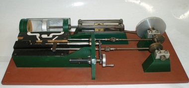 Bay Steamers Maritime Museum
model steam engine
This model was found in the collection of Bay Steamers Maritime Museum. It is not knowt who created it but it is supposed that it was constructed to educate the many masters of the Wattle in the operation of a steam engine - a not so common mode of power these days. A Bay Steamers Maritime Museum examined the model in March 2012 and discovered that is was in poor repair. Using his existing knowledge, and with reference to some historic texts, he made some repairs and returned the model to working order. Here is his anaylsis of the situation as an excerpt from the Bay Steamers Maritime Museum newsletter Steamlines May 2012 "I was confronted with a model of a steam engine used years ago as a training aid for hopeful steam engineers. Already having a knowledge of steam operations, I considered a museum write-up for that model a ‘piece of cake’. However, on turning the model’s crankshaft, the valve timing seemed ‘out of kilter’ with the movement of the piston. Problem was that the two eccentrics on the crankshaft were not properly secured to it. Eventually I fastened the two eccentrics to the crankshaft where I felt that they should be and then realized that one of them had a chain-driven valve-timing device attached. This would be adjusted while an engine was running to achieve best performance and fuel economy whilst in operation by accurately controlling the period of time during which steam under pressure from the boiler would be admitted to the cylinder and give greater time for the steam to expand in the cylinder, move the piston and turn the crankshaft and thus, drive the attached apparatus. When the valves were correctly set up it was then possible to get the model to function properly.The model comprises a green section, which is the actual the model mounted on a brown painted board. There are two parts of the model, painted white representing the steam passages, and black representing the cast- iron portions of the cylinder-block casting, and of the main valve sliding between the cylinder a second sliding valve. Of the black portions, one slides back and forth being connected to a rod which is connected to an eccentric clamped to the crankshaft and is the nearer to the flywheel of two eccentrics. This eccentric is attached to the crankshaft at an angle of 90 degrees to the crank-pin attached to the flywheel. To operate the model simply turn the flywheel by means of the handle attached to its crank-pin. A second eccentric is also attached to the crankshaft, further away from the first eccentric, and it is adjusted to operate 90 degrees from the first eccentric (that is, 180 degrees from the crank-pin) A piston (painted silver) is located in a plastic cylinder and has a piston rod which passes through one end of the cylinder, (in actual practice a steam-proof gland seals the cylinder against loss of steam) terminating in a cross-head slide between four rails guiding it. From this cross-head, a connecting rod joins the piston-rod to the flywheel via the crank-pin attached to the flywheel which is part of the crankshaft. (In actual practice, a flywheel may not be used, particularly in a multi-cylinder engine.) The white portions of the model painted nearest to the cylinder represent the two steam ports cast into the main cylinder block, whilst one section painted in between those two represents the exhaust outlet (which may be connected to a condenser to conserve water, or to the open air). The main slide valve has three white-painted portions painted thereon. It has two white-painted marks representing the steam passages to the steam ports into the cylinder, and a third section in between the other two, being that part of the valve through which exhaust steam passes in line with the ports in the cylinder block. By rotating the flywheel, the operations of an engine will be observed as steam is admitted to the main valve via the gap between the two jaws of two moveable portions of a second sliding valve which is operated by the second eccentric attached to the crank-shaft. This eccentric is used to finely tune the valve timing of this model to obtain best running results of an engine. There are various methods used for reversing a steam engine. model compound steam engine, steam engine, model, crankshaft, valve, flywheel, wattle, engineer, eccentrics -
 Moorabbin Air Museum
Manual (collection) - Pratt & Whitney Twin Wasp Series CG Engines parts list, Pratt & Whitney Engine Part List Twin Wasp Series CG
... Moorabbin melbourne Pratt & Whitney Engine Part List Twin Wasp ...Detailed list of parts and part numbers for Twin Wasp Series CG engines -
Moorabbin Air Museum
Manual (item) - Pratt & Whitney Spare Parts Catalogue for WASP Junior with R985 Engine
-
Moorabbin Air Museum
Manual (collection) - Rolls Royce Avon Mark 10900 schedule of spar parts, Schedule of Spare Parts for Avon Mark 10900 Series Aero Engine Change Units
-
Moorabbin Air Museum
Manual (collection) - Avon 10500 Series schedule of spare parts, Schedule of Spare Parts for Avon Mark 10500 Series Aero Engine Change Units
Schedule of spare parts for Avon 10500 series engine change units -
Moorabbin Air Museum
Manual (collection) - Engine electrical test panel, Engine Electrical Test Panel Description - Application - Operation - Maintenance - Spare Parts. Item No. 54
Item 54Brief overview of the operation, application, maintenance and spare parts for electrical test panel -
Moorabbin Air Museum
Manual (item) - Mirage III Atar Engines Spare Parts Manual, Tableau De Composition Illustre Turbo-Reacteur - Atar 09C
... Mirage III Atar Engines Spare Parts Manual ... -
Moorabbin Air Museum
Manual (Item) - Instruction Manual For Wolseley Aero Engines
Description: 182 pages. Published by Piper Aircraft Corporation. Published September 1968. Piper PA-18 & PA-18A Super Cub Aircraft Parts Catalogue Level of Importance: World. -
Moorabbin Air Museum
Manual (Item) - Wright Cyclone 9 Series R-1820-52 Engines
Description: 100 pages. Published by Wright Aeronautical Corporation. Published with materials from 1940-1945. Catalog Part No. 851653. Parts Catalogue for Wright Cyclone Aircraft Engines Series GR-1820G-200 Level of Importance: World. Author: Editor John W. R. Taylor -
Moorabbin Air Museum
Manual (Item) - Wright Cyclone Series 9Gc Engines
Description: SUPERSEDES PREVIOUS EDITION, PUBLISHED 1/5/1942. 134 pages. Published by Wright Aeronautical Corporation. Published 1/12/1942. Catalog Part No. 853544. Parts Catalogue for Wright Cyclone 9 Aircraft Engines Model R-1820-52 Level of Importance: World. -
Moorabbin Air Museum
Manual (Item) - Wright Cyclone Model R1820-74W And -76 Engines
Description: 199 pages. Published by Wright Aeronautical Corporation. Published on unknown date. Parts Catalogue for Wright Cyclone Series 9GC Aircraft Engines Level of Importance: World. -
Moorabbin Air Museum
Manual (Item) - Wright Cyclone Series 9Gc Engines Service Manual
Description: 69 pages. Published by Wright Aeronautical Corporation. Published December 1945. AN 02-35GG-4/No. 856098N1. Parts Catalogue for Wright Cyclone Model R1820-74W and -76 Aircraft Engines Level of Importance: World. -
Moorabbin Air Museum
Manual (Item) - Wright Cyclone Model Gr-1820-G-100 Engines
Description: 120 pages. Published by Wright Aeronautical Corporation. Published with materials from 1937-1941. Part No. 87983. Parts Catalogue for Wright Cyclone Series F50 Aircraft Engines Level of Importance: World. -
Moorabbin Air Museum
Manual (Item) - Wright Cyclone 9 Engines Instructions
Description: 150 pages. Published by Wright Aeronautical Corporation. Published with materials from 1940-1941. Part No. 851361. Parts Catalogue for Wright Cyclone Model GR-1820-G-100 Aircraft Engines Level of Importance: World. Author: W. Baird -
Moorabbin Air Museum
Manual (Item) - Beechcraft Queen Air Model 65 Parts Catalogue
Description: 23 pages. Published by Scottish Aviation. Published on unknown date. Scottish Aviation Prestwick Pioneer Alvis Leonides 502/4 Engine Specifications Book Level of Importance: World. -
Moorabbin Air Museum
Manual (Item) - Illustrated Parts Breakdown Ground Support Equipment Emb-110 Bandeirante
Description: Published on unknown date. Published by Latrobe Valley Aero Club. 20 pages. Piper PA-24 Comanche and Lycoming O-360A Engine Pilot's Handbook and Operations Manual Level of Importance: World. -
Moorabbin Air Museum
Manual (Item) - Cessna 210 Service Manual Supplement To The Single Engine Aircraft Manual
Description: Cessna Technical Parts Level of Importance: World. -
Moorabbin Air Museum
Manual (Item) - Illustrated Parts Breakdown Mirage Iii - O General Numerical Index Of Nato Numbers
Description: Mirage iii - O ATAR Engine Training Guide Level of Importance: . -
Moorabbin Air Museum
Manual (Item) - Teledyne Continental Motors C-125 C-145 0-300 Service Aircraft Engines Service Parts Catalog
... C-125 C-145 0-300 Service Aircraft Engines Service Parts ...Description: Teledyne Continental Motors From X30013 Level of Importance: . -
Moorabbin Air Museum
Manual (Item) - Continental Model Tsio-520 Series Aircraft Engines Service Parts Catelog
... Series Aircraft Engines Service Parts Catelog ...Description: Cessna Latest revision 1/12/76 Level of Importance: World. -
Moorabbin Air Museum
Manual (Item) - Illustrated Parts Catalog Vol.1 Prop-Jet Engines
Description: 370 pages. Published by General Motors Corportation, Allison Divison. Published 1/4/1958. ALL 010 Level of Importance: World. -
Moorabbin Air Museum
Manual (Item) - Illustrated Parts Catalogue For Prop-Jet Engines
Description: 40 pages. Published by Airspeed. Published on unknown date. Level of Importance: World. -
Moorabbin Air Museum
Manual (Item) - Parts Catalog Turboprop Engine Model 250-B17, -B17B, -B17C, -B17D
... Parts Catalog Turboprop Engine Model 250-B17, -B17B, -B17C.... 621.438.004.2 Level of Importance: World. Manual Parts Catalog Turboprop ...Description: 180 pages. Published by General Motors Corporation, Allison Division. Published 1958. 621.438.004.2 Level of Importance: World.