Showing 200 items
matching engineering design
-
 Ballarat Tramway Museum
Administrative record (series) - "BTPS Correspondence and design documentation", Warren Doubleday
... Yields information about the engineering design of the BTPS ...Record of Correspondence and associated documents.Letters etc in approx date order.Set of documents covering the engineering aspects of the development of the Ballarat Tramway Preservation Society trackwork, the design of the depot extension in the mid 1970s, financial, letters to and from the City of Ballaarat, meeting mintues, provision of a power supply by the SECV. Includes a drawing of SEC Assets in Wendouree Parade and inspection of air tanks.btps, bpts depot, depot extensions, depot trackwork, correspondence, meeting minutesbtps, bpts depot, depot extensions, depot trackwork, correspondence, meeting minutes -
 Wodonga & District Historical Society Inc
Photograph - Bethanga Bridge
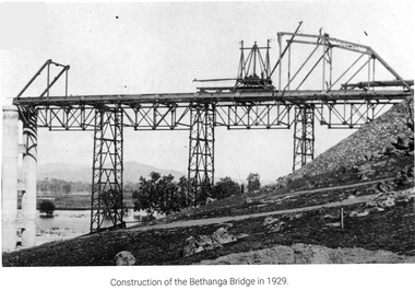
The Bethanga Bridge was built between 1927 and 1930 as a joint venture between Victoria and New South Wales and was a key element of the River Murray Waters Agreement. It consists of nine spans of 82 metres long. Each span is supported between double reinforced concrete pylons and a riveted steel camel back Pratt truss. The overall span of the bridge is a length of 752 metres. It was completed in 1929 at a cost of £194,000. The road deck was initially constructed from timber but was replaced in 1961 with a concrete waffle slab deck 7.7metres wide. In 1961 the bridge deck and truss structure were raised 300 millimetres to allow for the enlargement of the lake. The bridge was designed in NSW by road engineer Percy Alan and the trusses were built by the Charles Ruwolt Pty. Ltd. Charles Ruwolt Pty. Ltd. was originally established by Charles Ruwolt as a foundry at Wangaratta in 1902 and transferred its operations to Richmond, Melbourne in 1914. By 1938 it had become one of the biggest engineering companies in Australia. After Charles Ruwolt’s death in 1946, Vickers Ltd. acquired the company and in 1948 the firm became known as Vickers Ruwolt Pty. Ltd. Because of the Bethanga Bridge’s unique location, over the waters of a dam with the border running down the centre of the body of water, the Bethanga Bridge is the only built structure shared by both Victoria and New South Wales. As the border of New South Wales aligns with the southern bank of the Murray River all of the other bridges along its length are deemed to be in New South Wales. The Bethanga Bridge is listed on both the New South Wales State Heritage Register and the Victorian Heritage Database. In 2015 the Bethanga Bridge was nominated for a heritage award by the Institution of Engineering Australia.These images are significant because they document the construction of a bridge which links Victoria and New South Wales and has been recognised for its historical, technical and engineering significance.A collection of photos documenting the construction of the Bethanga Bridge which links the States of Victoria and New South Wales as part of the construction of the Hume Dam .bethanga bridge, hume dam constuction, charles ruwolt, percy allan engineer -
 Moorabbin Air Museum
Book - Aeronautical Engineering, Engineering Aerodynamics
... Aeronautical Engineering Aircraft design Overview ...Overview of the dynamics of aircraft design, circa 1936Overview of the dynamics of aircraft design, circa 1936 aircraft design -
 Eltham District Historical Society Inc
Photograph - Digital Photograph, Alan King, Monash Bridge, Hurstbridge, 23 January 2008
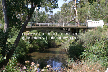
Monash Bridge spans the Diamond Creek at Hurstbridge. It was built in 1917 for the Shires of Heidelberg, Eltham and Whittlesea. It is considered Nillumbik Shire's finest engineered bridge and was construced by the engineering company of Sir John Monash. Covered under Heritage Overlay, Nillumbik Planning Scheme. Published: Nillumbik Now and Then / Marguerite Marshall 2008; photographs Alan King with Marguerite Marshall.; p117 Monash Bridge is considered the Shire’s finest engineered bridge and was constructed by the engineering company of that great Australian, Sir John Monash.1 The bridge spans Diamond Creek on the Hurstbridge-Arthurs Creek Road, linking Hurstbridge with Yarrambat and Arthurs Creek. Monash Bridge, also called Hurst’s Bridge, was built in 1917, by the Reinforced Concrete and Monier Pipe Construction Company Pty Ltd, for the Shires of Heidelberg, Eltham and Whittlesea. Although Monash was probably in action overseas during World War One when the bridge was designed and constructed, he evolved the basic design in the 1900s and it was a standard design for the firm. However J A Laing, a designer at the firm, was probably the designer, as his initials are on bridge drawings held by the Eltham District Historical Society.2 The bridge is an excellent early Australian example of an open spandrel reinforced concrete arch bridge and has a single span of 29 metres. It is unusual in Victoria, but similar to many reinforced concrete arch bridges in Europe and America, built from the late 19th century. In Victoria, Monash pioneered the use of reinforced concrete – then a revolutionary construction material. His company, Monash & Anderson, had the exclusive licence for the Monier patent for the system of reinforced concrete construction for Victoria and New South Wales. A well-known example of the Monier arch bridge is the Morell Bridge in South Yarra. The sweeping arch of the Monash Bridge combines grace and utility and blends with the surrounding rural landscape. Its design and construction have allowed it to carry increasing volumes of heavy traffic, but in modern times the one lane is considered by some to prevent easy passage through Hurstbridge. However others consider this an asset to deter too much more traffic, which would diminish Hurstbridge’s charming rural character.3 This is the third bridge across the Diamond Creek at this site. The original bridge was a log bridge upstream, constructed in the 1850s by early settler, Henry Hurst, after whom Hurstbridge was named. The bridge spanned the creek, where it divided his family’s property. In the 1880s a timber bridge replaced it, known as Hurst’s Bridge. However a more permanent bridge was considered necessary when the new railway arrived in 1912, bringing with it expectations of growth in the town and the surrounding fruit-growing district. Monash Bridge’s official opening on November 3, 1917 was a gala occasion, which took place before about 1000 spectators. Two who attended the opening had a particularly sound knowledge of the locality. One was Fred Hurst, Henry’s brother, who used to ford the creek at or near the bridge’s site more than 50 years before. The other was John McDonald of Arthurs Creek, who had built the old wooden bridge over the creek about 40 years earlier.4 Although John Monash was a fine engineer, his fame came from his brilliant war career, rather than from his engineering or his many other achievements. Monash was Corps Commander of the Australian Forces. His brilliance was recognised with his awards: Knight Grand Cross of the Order of St. Michael and St. George, and Knight Commander of the Bath. Monash was also decorated by the French, Belgian, and American Governments.5 After the war, Monash worked in many prominent civilian positions, the most notable as head of the Victorian State Electricity Commission. He was a leading and loved public figure, involved in many public and private organisations. He was president of the Australian Zionist Federation and involved in the Boy Scouts. Monash University is named after him. By the 1920s Monash was probably regarded as the greatest living Australian.6 Despite most of his life working as an administrator and leader, rather than a fighting soldier, he became integral to the ANZAC legend. Monash died in 1931.This collection of almost 130 photos about places and people within the Shire of Nillumbik, an urban and rural municipality in Melbourne's north, contributes to an understanding of the history of the Shire. Published in 2008 immediately prior to the Black Saturday bushfires of February 7, 2009, it documents sites that were impacted, and in some cases destroyed by the fires. It includes photographs taken especially for the publication, creating a unique time capsule representing the Shire in the early 21st century. It remains the most recent comprehenesive publication devoted to the Shire's history connecting local residents to the past. nillumbik now and then (marshall-king) collection, hurstbridge, monash bridge -
 Eltham District Historical Society Inc
Photograph - Digital Photograph, Marguerite Marshall, Smith Dam, Karingal Drive, Eltham, 19 September 2006
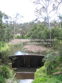
The dam at the entrance to the Nerreman Gateway in Eltham was built according to an internationally acclaimed theory developed by the builder's father. In 1920, Victorian engineer B.A. Smith was awarded the American Society of Civil Engineers J. James R. Cross Gold Medal for his Technical Paper titled 'Arched Dams'. It was the first time this medal had been awarded outside the United States. The concrete arched dam across the Eltham West Drain was built in 1940 by B.A. Smith's son and engineer, D. B. (Bernie) Smith to water the 24 acre (9.75 ha) hobby farm owned by himself and new wife, Isa Smith. Upon completion of the dam a pump-house was constructed beside the creek but before the water could be pumped up the hill they had to dig a trench and lay 500m of 100mm water main to an elevated holding tank. The Smiths made the pump-house their home for several years until they constructed their home at the top of the hill overlooking Eltham and views extending to Kinglake. Following Bernie's death in 1983, Nerreman Park was subdivided between 1993 and 1995. Gordon Ford designed the landscaping and the pump-house was demolished. Covered under Heritage Overlay, Nillumbik Planning Scheme. Published: Nillumbik Now and Then / Marguerite Marshall 2008; photographs Alan King with Marguerite Marshall.; p137 The dam at the entrance to the Nerreman Gateway in Eltham, was built according to an internationally acclaimed theory developed by the builder’s father. In 1920, Victorian engineer B A Smith was awarded the American Society of Civil Engineers J. James R. Croes Gold Medal, for his Technical Paper titled Arched Dams. It was the first time this medal had been awarded outside America. An international example of the application of Smith’s work can be found in the design of the Hoover Dam on the Colorado River, Nevada, USA. Built between 1930 and 1936, it is recognised by the ASCE as one of ‘America’s Seven Modern Civil Engineering Wonders’.1 The concrete arched dam across the Eltham West Drain was built by B A Smith’s son and engineer, D B (Bernie) Smith. Bernie’s dam followed his father’s theory, having a curvature that takes maximum advantage of concrete’s great strength in compression. The water load is carried into the abutments because of this curvature, which permits a wall thickness of only 225 millimetres thick at its crest, despite the dam’s capacity of more than 4.5 megalitres. The Eltham dam was designed to water the 24 acre (9.75 ha) hobby farm belonging to newly married couple Bernie and Isa Smith. Bernie, from Armadale, and Isa, from a farm at Tyntynder near Swan Hill, were attracted to the hilly topography and the creek running through the property. It extended from Ryans Road, Eltham, to Karingal Drive, Montmorency and was adjacent to Meruka Park. The Smiths named it Nerreman Park using the Aboriginal word Nerreman meaning ‘River Bend’ as their creek had a pronounced bend.2 In 1940 the first thing Bernie did was to build a dam, and with Isa’s help, a pump-house, to secure a water supply for their cattle, pigs, chickens, orchard and vegetable gardens. It was also available for the fire-plugs, which they placed all over the property in case of bushfire. The couple built the pump-house beside the creek and installed a Tange three-plunger pump, which had originally supplied the City of Wodonga with water. But before the Smiths could pump water up the hill from the dam they had to dig a trench and lay about 550 yards (500m) of a four-inch (100mm) water main up to an elevated holding tank. The trench was dug with a single furrow plough drawn by an old draught horse. Living in rough conditions did not deter the Smiths, who made the pump-house their home, where they still lived when their first child was born in 1944. They later built their home at the top of their property overlooking Eltham, with magnificent views to Kinglake, the Dandenong Ranges and Melbourne. From 1946 it took them almost 20 years to complete the 36-square house with its 12-foot (3.6m) high ceilings. Material for the concrete roof and walls faced with sandstone, was ripped out of the ground on their property by plough pulled by tandem Clydesdale horses. Isa was a strong woman – two days before their second child was born – she set three huge sandstone boulders in place in the bottom wall of the garage. She also mixed all the cement for the house. A collapsed kitchen wall did not discourage her from rebuilding it in a week, while her husband was away working in the country. She later recalled: ‘We stood back to admire this beautiful wall we’d built and while we were looking at it, it came tumbling down’.3 Following Bernie’s death in 1983, Nerreman Park was subdivided, between 1993 and 1995. Local Gordon Ford designed the landscaping and the pump-house was pulled down. But the dam remains as a reminder of exceptional engineering4 – and of a remarkable couple.This collection of almost 130 photos about places and people within the Shire of Nillumbik, an urban and rural municipality in Melbourne's north, contributes to an understanding of the history of the Shire. Published in 2008 immediately prior to the Black Saturday bushfires of February 7, 2009, it documents sites that were impacted, and in some cases destroyed by the fires. It includes photographs taken especially for the publication, creating a unique time capsule representing the Shire in the early 21st century. It remains the most recent comprehenesive publication devoted to the Shire's history connecting local residents to the past. nillumbik now and then (marshall-king) collection, eltham, karingal drive, smiths dam, bernie smith, gordon ford, isa smith, nerreman gateway, nerreman park estate, dams -
 Vision Australia
Machine - Object, Minnie Crabbe, Braille printing press, 1934
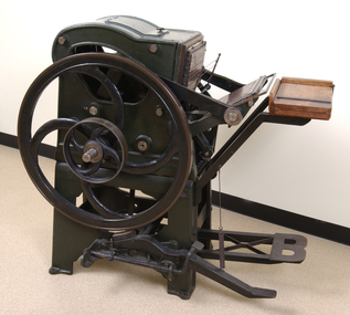
In 1934, the Victorian Association of Braille Writers annual report advised that it had acquired a Crabb-Hulme Braille Printing Press. Two years in development, the Press was designed by Miss Minnie Crabb (the librarian) and built to her specifications by Mr Hulme. Invented to produce ephemeral material quickly, such as programs, catalogues and newsletters, and provided more opportunities for information to be quickly sent out to Braille readers.Steel and cast iron printing press with two wheels on left hand side and two foot levers to operate a wheel on the right hand side.victorian association of braille writers, braille equipment, minnie crabb -
 Melbourne Tram Museum
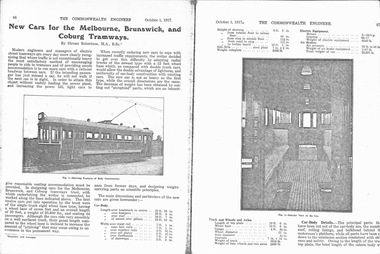
Document - Report, The Commonwealth Engineer, Electrical Engineer, The Electrical Engineer and Merchandiser, Noiseless Tramcar - first Australian Vehicles - Bogies fitted have special noise reducing features, 1917 - 1951
... W5 class SW5 class PCC Class Tramcar Design Electrical ...Set of 12 reports, photocopied onto heat sensitive paper from various magazines. Documents match the image numbers. .1 - 2 pages, from The Commonwealth Engineer, 1/10/1917 - "New Cars for the Melbourne Brunswick and Coburg Tramways", written by Straun Robertson. .2 - 2 pages, from The Commonwealth Engineer, 1/3/1919 - "Double Bogie Combination Tram Car - St Kilda Brighton Electric Line". .3 - 2 pages - Electrical Engineer - 15/6/1924 - "One Man cars for Melbourne and Geelong Vic. The Brill Birney Safety Car" .4 - 1 page - Electrical Engineer - 15/11/1925 - "Standard Car for Melbourne Tramways" - has sketch of W2 369. .5 - 2 pages - Electrical Engineer - 15/8/1927 - "New Bogie car for Melbourne Tramways" Y class. .6 - 2 pages - Electrical Engineer -15/3/1936 - "Tramcar of New type for Melbourne - Large car for Two-man or One-man operation" - Y1 class .7 - 3 pages, The Electrical Engineer and Merchandiser - 15/3/1932 - "Modern Tramcars for Melbourne - Design for reduction of noise and construction with electrical Welding" W3 class. .8 - 2 pages, The Electrical Engineer and Merchandiser - 15/11/1933 - "New Tramcars for Melbourne" - has sketch of the W4 class tram. .9 - 3 pages, The Electrical Engineer and Merchandiser - 16/12/1935 - "Melbourne's Lates Tramcars, comfortable Accommodation and modern traction equipment" - W5 class .10 - 3 pages - The Electrical Engineer and Merchandiser - 15/3/1939 - "Improved Type Tramcar - advanced truck design, pneumatically operated doors, special lighting, acceleration 3pmh per sec." SW5 class. .11 - 3 pages - The Electrical Engineer and Merchandiser - 15/9/1950 - "Noiseless Tramcar - first Australian Vehicles - Bogies fitted have special noise reducing features - motor drive through bevel gears, dynamic braking" - PCC 980 (See also Reg Item 5601 for a similar report) .12 - 1 page - handwritten on the rear of a copy of item 11 - Editorial from the Oct. 1951 issue of same magazine looking at the rate of acceleration. Reprint of .7 added 30/7/2019, from papers ex Robert Green - in poor condition, has been folded, both left and right hand edges in multiple tears. The photos are good. Measures 282H x 220W.trams, tramways, mmtb, mbctt, new tramcars, vr, bogie trams, birney, x class, w2 class, y class, y1 class, w3 class, one man trams, w4 class, w5 class, sw5 class, pcc class, tramcar design, electrical engineering -
 Melbourne Tram Museum
Document - Report, Melbourne & Metropolitan Tramways Board (MMTB), "1041 Prototype Tram", 21/03/1974 12:00:00 AM
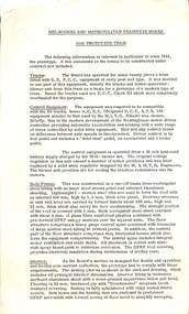
Report - three foolscap sheets, titled "1041 Prototype Tram" outlining the basis of the construction of the prototype tram. Gives information on the trucks, control equipment, body frame, interior, doors and windows, heating and ventilation, lighting, destination equipment and other equipment. Notes the construction of the new trams by Commonwealth Engineering and the basis for the design from those of Gothenburg Sweden. Dated 21/3/1974trams, tramways, mmtb, prototype tramcar, 1041, new tramcars -
 Melbourne Tram Museum
Document - Instruction, Precision Circuits, Selectronic Components, "Wheel diameter compensator - Kit Details and installation instructions", 1984
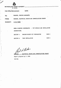
.1 - Instruction - approx. 50 pages, A4 pages with some foolscap pages detailing the: "Wheel diameter compensator - Kit Details and installation instructions", prepared by the Metropolitan Transit Authority for Manager Preston Workshop by the Manager electrical design and communications branch - P. CussZ. Dated July 1984 for fitting to Z1 and Z2 trams. Includes an "Owners' Manual" in a plastic folder, prepared by Selectronic Components of Bayswater. .2 -set of 3 drawings showing the layout for the circuit boards prepared by Precision Engineering dated 29-8-1991, in a labelled plastic folder.trams, tramways, z class, maintenance, electrical engineering, electrical equipment, wheels, the met, tram 980 -
 Melbourne Tram Museum
Pamphlet, Austbreck, "Austbreck", c2000
Pamphlet or Catalogue - 16 A4 pages + card cover - full colour centre stapled titled "Austbreck" providing a detail over view of the company, its products and locations. c2000 Company provides pantographs, overhead traction systems for rail and tram, crane trolley systems, design and project management. Includes brush holders, isolation systems and insulation.trams, tramways, overhead, electrical engineering, trolley wire, pantographs, electrical equipment -
 Melbourne Tram Museum
Document - Report, Melbourne & Metropolitan Tramways Board (MMTB), "Information - Tram 980 (PCC Equipment)", Feb. 1964
Report - carbon typed copy - 43 foolscap sheets bound within a brown card folder, stapled, with signs of an adhesive tape binding on the outside. Titled "Information - Tram 980 (PCC Equipment)", dated February 1964, prepared by the MMTB Engineering Department Testing Department Report No. I 5/1/144. Signed by W. Hines 6/2/64, report prepared by CLF. Provides a synopsis of the report, purpose of investigation, design, operational history, time in workshops, maintenance program, schedule speeds, riding qualities, has appendices with design modification, list of time in workshops, PCC tramcars maintenance program, workshops maintenance of ten typical trams, MMTB Tramcar Schedule speeds. Includes photographs of the failure of the main body transom and the replacement one, and two graphs. Second copy added 31-5-2016 from donation of Geoff Warburton. This copy - has red binding tape.trams, tramways, testing, pcc, preston workshops, reports, specification, tramcar manufacture, tramcar design, maintenance, tram 980 -
 Bendigo Historical Society Inc.
Newspaper - JENNY FOLEY COLLECTION: ON TOUR
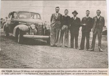
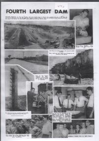
Work started on the Lauriston Reservoir in 1939 as part of the Coliban water system and was officially opened by Victorian Premier, Albert Dunstan in 1941. Capacity was increased in 1946 when steel spillway gates were added. Although these had been part of the original design they could not be added at the time of the building because of post-war steel shortages.Bendigo Advertiser ''The way we were'' from 2003. on tour: school of mines civil engineering students visit the construction site of the Lauriston Reservoir in 1940. Left to right: Les Nankervis, Ron Watts, instructor Syd Power, an unknown student and Cliff Binks. The clip is in a folder.newspaper, bendigo advertiser, the way we were -
Moorabbin Air Museum
Manual (item) - RAAF Specification Engineering AC180 AC181 Aircraft Development Specification for the Basic Training Aircraft test, Inspection and Acceptance specification for the Basic Pilot Training Aircraft
RAAF Design SpecificationRAAF SPECIFICATION AC180 AC181raaf history and aircraft -
 University of Melbourne, Burnley Campus Archives
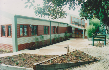
Photograph - Colour print, AGFA, Engineering Building, Unknown
... engineering building. burnley garden design Colour ...Colour photograph. The Engineering Building.engineering building., burnley, garden design -
Moorabbin Air Museum
Book - Aeronautical Engineering, Weight-Strenght Analysis of Aircraft Structures
... Aeronautical engineering Aircraft structural design ...Overview methods for analyzing & predicting structural weight of aircraft & missiles, circa 1952non-fictionOverview methods for analyzing & predicting structural weight of aircraft & missiles, circa 1952aircraft structural design, structural-weight equations, material properties & behaviour -
 Glenelg Shire Council Cultural Collection
Plan, Specification Oceanographic Research Vessel C.S.I.R.O
Set of plans relating to CSIRO Research Vessel 1980A set of plans and drawings relating to the CSIRO research vessel. There are 10 clear plastic pockets each containing drawings. The collection has a hard plastic cover. There are two loose leaf pages at the front of the collection - a title page and a list of contents. non-fictionSet of plans relating to CSIRO Research Vessel 1980nautical, seamanship, maritime, vessel, plans -
 Flagstaff Hill Maritime Museum and Village
Functional object - Water Boiler, Jackson Boilers Ltd, 1920s
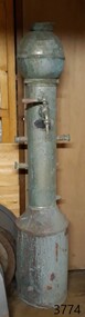
Jackson Boilers Ltd., brass founders, electro platers and sheet metal works made this tube water boiler. It was a fitting in the vessel Reginald M, a small cargo ship built at Port Adelaide in 1922 and named after her builder and first owner, John Murch. The Reginald M was launched at Largs Bay, South Australia, in 1922 to carry cargo around South Australia that included guano, barley, wool, horses, cattle, timber, explosives, potatoes, shell grit, and gypsum. It passed through numerous owners over the years and primarily maintained its purpose as a cargo vessel. In 1975, the decommissioned Reginald M was purchased by Flagstaff Hill Maritime Museum as an attraction. Although restoration efforts were undertaken and maintained for the craft above the water line, deterioration occurred below the surface and resulted in the ship being unsafe for visitors to board. It was broken up and removed from Flagstaff Hill in 2018, but items such as the historical boiler remain in Flagstaff Hill’s Collection. JACKSON BOILERS LTD.: - In 1911, Henry Jackson was the Managing Director at Jackson Boilers Ltd. He had gained around 30 years’ experience as a tin plate worker, plumber and gas fitter at Ilkey in 1881, then at Leeds by 1901. By 1921, he had changed employment from Jackson Boilers to Managing Director of Patent Water Boilers. During World War I, Jackson Boilers Ltd of Leeds performed war work like many other manufacturers at that time. The firm made cases for the explosive picric acid and electroplated fuse hole plugs. In 1918, the firm employed 15 males and 19 females. Jacksons Boilers became very successful throughout the first half of the twentieth century with showrooms and sales offices in Scotland, the Midlands and Southern England. It also had an office in Dublin, Ireland. In the post-war 1920s, the firm’s production included instantaneous water boilers and coffee machines for cafes, restaurants and canteens. Jackson Boilers also began to supply shipping lines with catering water boilers for their ships. The firm applied for a USA patent for the tube boiler in 1930, for the design which appears to have been invented in 1926. A 1971 advertisement adds the credentials, Members of the Catering Equipment Manufacturers’ Association. The tube water boiler was designed specifically for use in a ship's restaurant or dining area and patented by Jackson Boilers Ltd. of Leeds. The boiler is significant as a patented design, illustrating the evolution of maritime, commercial and domestic water boilers that have led to many innervations and improvements in today's boilers that are used in heating and in producing hot water for domestic and catering use. It is also significant as it is one of the earlier boilers the Jackson company made in the early 1920s before they applied for a US patent on their revised design in 1926.Water boiler, free standing Jackson's Tube boiler. A tall metal cylindrical stand with a metal sphere on top and several pipe fittings on the sides. A brass tap with a lever handle is connected to the front. A plaque with maker's details is attached under the tap. Details are also impressed into the cylinder above the tap.Jackson Boilers Leeds Ltd. "JACKSON'S PATENT" . Other details indecipherable. flagstaff hill maritime museum and village, flagstaff hill maritime museum, flagstaff hill, maritime museum, maritime village, warrnambool, great ocean road, leeds, jackson boilers ltd, jackson boilers, henry jackson, brass founders, electro platers, sheet metal works, patent water boilers, leeds manufacturer, tube water boiler, domestic boiler, tube domestic boiler, tube boiler, water heaters, water boilers, self-feeding water boilers, sheet metal work instantaneous water heaters, engineering, allied trades, metal workers, metal trade, food machinery, hospitality equipment, ship equipment, ship water boiler, ship heater, catering boilers, café boiler, restaurant boiler, canteen boiler, catering equipment manufacturers’ association, cema, kitchen equipment, kitchen appliance, war work, world war i, wwi, picric acid, picric acid cases, fuse hole plugs, electro plated fuse hole plugs, reginald m, cargo ship, port adelaide, 1922, john murch -
 Geoffrey Kaye Museum of Anaesthetic History
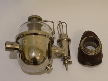
Equipment - Inhaler, Bruck, 1908
The Bruck Inhaler is a modification of the Clover Inhaler, designed by Lambert Bruck. Bruck added a glass dome which enabled the level of ether to be monitored during administration. This was a revolutionary change as it removed guess work from the process.The Bruck Inhaler is a historically, aesthetically and scientifically significant piece. The basic design is based on the Clover Inhaler, but with a rounded bottom. The idea of a glass viewing window was possibly inspired by Wilson-Smith Inhaler. The Bruck Inhaler is historically significant as it is the first inhaler to be made with a completely clear lower glass section. This improved the usability for the ether administrator, and eliminated much of the guesswork associated with dosage and ether levels, which in turn improved the patient experience. This piece provides a strong local link to both anaesthetic and general medical practice at the turn of the century. The design is credited to Ludwig Bruck of Sydney, and was presumably manufactured in the same area. Bruck, as the attributed designer, holds much relevance to the significance of the object, as connected with him is much historical information about the social context of medical practice. Ludwig Bruck was a prominent figure in the medical industry. He started his medical career in Sydney as a Medical Transfer Agent, and later owned a shop at 16 Castlereagh Street, Sydney. This business is listed in the 1903 Register of Firms as a Medical Agent and Importer of Medical Instruments and Books. Bruck was vocal as a journalist and published analyses of medical statistics, as well as the well known Australasian Medical Dictionary and Handbook, which included the “List of Unregistered Medical Practitioners”. Ludwig Bruck was an immigrant. He was of German descent, which placed him in a precarious position within Sydney society during the turn of century. Bruck conducted several public conversations with prominent members of the Australian Natives Association through the Sunday News in regards to his disagreement of the employment of medical practitioners by the ANA specifically to corroborate their health insurance policies. He was also a stalwart supporter of the Australian arm of the British Medical Association, being the publisher of the first and subsequent editions of The Australian Medical Gazette. Bruck chose to end his life with a combination of poison and chloroform on 14 August 1915, after being accused of trading with the enemy during World War One. His suicide note stated his horror at leaving his business partner to deal with the tarring of his reputation as the reason for his decision. The Bruck Inhaler has aesthetic significance as it is a beautiful example of turn of the century surgical design and craftsmanship. Aseptic methods of surgery were well known by 1909, and the aesthetic design of the Bruck Inhaler conformed to these principles. The ability for the surgeon to unscrew, clean and sterilize each part of the Inhaler contributes to the streamlined design of the piece. The Buck Inhaler holds scientific significance. There is the capacity for further research to be undertaken on the object. Geoffrey Kaye often collected multiple examples of equipment, usually one for reverse engineering and another for teaching. There are currently two examples of the Bruck Inhaler in the collection, presenting an opportunity for further technical research on the object. The inhaler is oval shaped with one half made of glass to allow observation of the ether level. A vertical cross tube, 22mm in diameter passes between the face-piece and the bag [missing]. There is a stopcock for admission of oxygen or nitrous oxide opposite the bag attachment. There is a central tube, 28mm in diameter, with controllable ports on either side. There is also a tear-drop shaped fask mask.Hand engraved on side of base: L. Bruck / Sydneyclover, joseph, bruck, lambert, inhaler, rebreather, nitrous oxide, oxygen, williams, probyn -
 Geoffrey Kaye Museum of Anaesthetic History
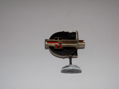
Equipment - Inhaler, Clover (sectioned)
Dr. Joseph Clover (1825-1882), an English physician, first described his Portable Regulating Ether Inhaler on Jan. 20, 1877. Clover was an especially sought after anesthesiologist and early pioneer in the specialty. This was the best-known of many inhalers that Clover designed. The dome-shaped reservoir was turned to points on a control dial to gradually increase or decrease the percentage of the air that passed over the ether. Several inventors based new inhalers on this, while the original continued to be manufactured as late as the beginning of WWII. Dr Geoffrey Kaye sectioned equipment, enabling medical students to see the inner workings and gain insight into the engineering of the equipment.Cross section of Clover's inhaler attached to a circular metal base.Handwritten on white sticker at rear: P / 26 / B •White print on blue sticker: O.2.3. •Engraved on dome side of inhaler: G. Kaye sect. 1939.joseph clover, geoffrey kaye -
 Bendigo Historical Society Inc.
Document - Collection of photographs from newspaper on a single page
John Perry Collection. Laminated copy of page from 'Weekly Times' newspaper, February, 1962. Nine images relating to establishing and building Eppalock Reservoir, 15 miles from Bendigo. The dam was built by the State Rivers and Water Supply Commission of Victoria. The dam wall height is 45 metres (148 ft) and the main embankment is 1,041 metres (3,415 ft) long. At 100% capacity the dam wall was designed to hold back 304,651 megalitres (6.7014×10¹⁰ imp gal; 8.0480×10¹⁰ US gal) of water. The surface area of Lake Eppalock is 3,011 hectares (7,440 acres) and the catchment area is 2,124 square kilometres (820 sq mi). The controlled spillway is capable of discharging 8,040 cubic metres per second (284,000 cu ft/s). Lake Eppalock supplies both stock and domestic water to the Campaspe irrigation district. It also serves as a water supply to Bendigo and Heathcote and, in more recent times, Ballarat. The lake is a major attraction for those engaging in watersports, with a number of tourist parks and accommodation facilities available. Permissible activities on the lake include high-speed boating, water skiing, sailing, canoeing, fishing and swimming. The lake's water levels were low for approximately eight years between 2002 and 2010 during a prolonged drought, which restricted the amount of recreational activity until rainfall in the latter half of 2010 returned the lake to 100 percent capacity. Built between 1961 and 1964, Lake Eppalock remains the only water storage on the Campaspe River system. dam, engineering, water, eppalock