Showing 276 items matching "plug"
-
 NMIT (Northern Melbourne Institute of TAFE)
Video recordings: Instructional NMCOT and NMIT 1980s
U-Matic Video recordings (Master tapes) mostly dated in the 1980s. Alphabetically: A house of all trades [No date] (14 min). An Introduction to floor managing An introduction to floor managing. Architrave: running the mould. Solid plastering. [No date] (17 min). Boom spray calibration (turf management). [No date] (6 min). Drafting. Module C51 Step no 4.(footwear) (1987) [No time] (Edit master) Fibrous plastering (1988) (Duration 11.00) Firm foundations: presenting a case for finance (21 min) Flux cored arc welding. Roof plumbing: fitting outlet. Friction in engineering (20 min). Grafting and budding techniques. (1986) (Duration 10.00) Horticultural courses at Collingwood College of TAFE. [No date] (10 min). Making a hand made thread. [No date] [No time] Making a hand-made thread Manual metal arc welding [No date] (24 min). Master saddlery; stitching: 1 saddle, 2 back. Microphones and their use in location sound recording [No date] [No time] Microphones and their uses in location sound recording Mold cutting [No date] [No time] Plain sailing: a film about business planning (20 min). Potentiometers, Part 1. (1983)(16 min). Preparation of artwork for video tape production (1977)(162 min). Preparation of instructional video tapes (1977)(12 min). Roof plumbing: fixing eaves cutters: Part 1 – fixing methods. [no time] Saddlery: hand stitching Safe saddle making. (1985) [No time] Solid plastering/Setting in Plaster and lime (1987) (Duration 10.00) (Edit master) Special electronic effects in video production. [No date] [No time] Splitting a stone using plugs and feathers [No date, possibly 1987] (Duration 9.40) (Master edit) The necessary art; videotape lighting: practical tips. (1974)(15 min). Tiling a staircase (1987) (Duration 25.00) (master edit) Water resistant board (W.R. Board): What is a word processor (26 min). WR Board northern metropolitan college of tafe, handbooks, nmit -
 Ballarat Tramway Museum
Photograph - Digital image, 8/03/1955 12:00:00 AM
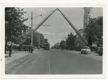
Yields information about the preparations undertaken by the Ballarat Fire Brigade to form a welcoming arch for a visiting Governor General..Digital image from the Wal Jack Ballarat Album of Ballarat No. 20 passing under the two LaFrance fire brigade ladders forming an arch outside the Ballarat City Fire station on 8/3/1955 to greet the Governor General Sir William Slim, Sturt and Raglan Streets. Wal's album notes say "No. 20 passing under 2-100' extension ladders as an arch to welcome Sir William Slim, Governor General. Sturt and Raglan St 8-3-1955." See image i2 for rear of photograph. See image i3 for hi res scan of print. See image i4 for hi res scan of negative\ Neville Britton of the BTM advised 2/5/2020: Seven LaFrance 100' ladders built by the American LaFrance Company, of Elmira, New York arrived in Australia in 1942 as part of the WW2 lend lease program. One each to Perth, Brisbane and Adelaide. Four initially to the MFB but within a short period of time went to the CFA. One each to Geelong City FS, Ballarat City FS and Bendigo FS. The fourth was a stand in and was located at the Ballarat FS when not required. Thus the two ladders in the photo at the Ballarat City FS. I was a volunteer at Ballarat City FB from 1967 and commenced my career employment there in 1970. The two LaFrance ladders were still in Ballarat at that time. In the mid 70's the 'spare' was allocated to the Dandenong FS. They were retired in the 1980's. The four Victorian ladders still survive. Ex Geelong City is at the Fire Services Museum Victoria. They have a second one that was acquired by a private collector. It was neglected and returned to the FSMV in poor condition. Ex Ballarat City was driven to Sydney and remains at the Museum of Fire at Penrith. The fourth one was acquired by a private collector and stored in a shed in North Geelong and never moved. He recently died and it may have been sold. They had a V12 petrol engine with all ignition parts duplicated. So two Distributors, two ignition coils and two spark plugs per cylinder. Splash feed engine lubrication.On rear in ink. Top right hand corner "T175" within the Wal Jack stamp. "SEC Ballarat No. 20 passing under the two LaFrance yank extension ladders ( to greet the Governor General Sir William Slim) Sturt and Raglan Streets. and the date "8 Mar 1955"trams, tramways, sturt st, governors, fire station, ceremonies, tram 20 -
 Department of Energy, Environment and Climate Action
Aerial Drip Torch (ADT) or "Dragon"
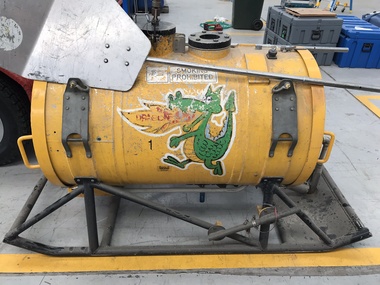
The Aerial Drip Torch (ADT) was an idea conceived in Canada in the 1970s by John Muraro It was developed in 1982 by the New Zealand Forest Service to become the Ashley Aphid Helitorch. Forestry Tasmania acquired one of the machines and modified it in February 1987. Also known as a dragon helitorch it consisted of a large 135-litre tank containing jellied petrol, a displacement pump, propane ignition system, burner nozzle and fire extinguisher system. It was first trialled in Victoria at Swifts Creek in 1991 and the Aerial Drip Torch (ADT) has now become standard practice.Two Aerial Drip Torches (ADTs) were built in the 1990s by the Fire Equipment Development Centre at North Altona, They were developed in conjunction with the Department of Conservation and Land Management in Western Australia. The first was trialled during the 1991/92 autumn burning season. The machine proved to be successful and a second machine was introduced in 1998 to assist with burning operations across the State. The ADTs were commonly used for regeneration burning (controlled burning of logging slash). The first ADT introduced in 1992 had a dry weight of 160kg and a capacity of 130 litres, providing about an hour of operation. Following initial use, systematic modifications were adapted including improved ignition of gel at the drop tube, installation of an air bleed valve at the pump to assist pump priming and improved mounting brackets for the CO2 bottles and propane canister attached to the machine. The second, and lightweight ADT, introduced in 1998 had a dry weight of 68kg and a capacity of 200 litres due to a smaller lightweight frame and plastic (Polyfin) tank. In operation the ADT is suspended below a helicopter via four strops attached to the vessel and a cable to the helicopter cargo hook. Gelled fuel is dispensed via a drop tube which is attached to the pump outlet of the machine, and ignited via a gas torch. Safety features built into the first ADT were: a brass melting plug designed to be activated at 200 C bursting disc designed to burst at170 Kpa should the vessel over pressurise. a pressure relief valve set to 35 Kpa ( vessel operated between 16 &34 Kpa) a low pressure sensor designed to shut down the machine should the vessel pressure drop below 15Kpa. the vessel is filled with CO2 above the gelled fuel to eliminate ignition with in the vessel. CO2 is used to expel any residue of ignited gel from the drop tube to prevent ignition when flying outside the boundaries of the burning area. See FIRE EQUIPMENT NOTE - 46 [ https://drive.google.com/file/d/1CKtcH-3rUlrtbE9dkNP27PYT2-raVVhF/view ]forests commission victoria (fcv), bushfire, bushfire aviation, planned burning -
 Ballarat Tramway Museum
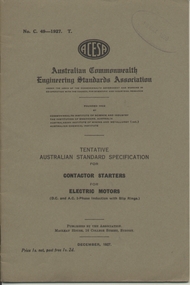
Book, Australian Commonwealth Engineering Standards Association, "Contactor Starters for Electric Motors", "Dimensions of insulated annealed copper conductors for electric power and light including voltage tests", "Vulcanised Fibre for Electrical Purposes", "Bus-bars and connections constructed of bare copper or aluminium", "Fixed Condensers for Radio Reception Purposes", "Graphic (Recording or chart recording) ammeters, voltmeters and wattmeters.", "5-Amp two pin wall plugs and sockets for domestic purposes (without earthing connection)", "Electric Cable Soldering Sockets", "Graphical Symbols and Schedule of Outlets for the Electrical Equipment of Buildings", "Porcelain Insulators for overhead powerlines and outdoor switching Structures", 1927-1939
.1 - Book - 28 pages + grey covers, side stapled, issued by the Australian Commonwealth Engineering Standards Association, Tentative Australian Standard - "Contactor Starters for Electric Motors" C49-1927, December 1927. .2 - Book - 56 pages + grey covers, side stapled, issued by the Australian Commonwealth Engineering Standards Association, Tentative Australian Standard - "Dimensions of insulated annealed copper conductors for electric power and light including voltage tests" C50-1928, June 1928. .3 - Book - 36 pages + grey covers, side stapled, issued by the Australian Commonwealth Engineering Standards Association, Tentative Australian Standard - "Vulcanised Fibre for Electrical Purposes" C51-1928, May 1928. .4 - Book - 16 pages + grey covers, side stapled, issued by the Australian Commonwealth Engineering Standards Association, Tentative Australian Standard - "Bus-bars and connections constructed of bare copper or aluminium" C52-1928, May 1928. .5 - Book - 16 pages + grey covers, side stapled, issued by the Australian Commonwealth Engineering Standards Association, Tentative Australian Standard - "Fixed Condensers for Radio Reception Purposes" - C53-1928, February 1928. .6 - Book - 32 pages + grey covers, side stapled, issued by the Australian Commonwealth Engineering Standards Association, Tentative Australian Standard "Graphic (Recording or chart recording) ammeters, voltmeters and wattmeters." C54-1928 March 1928. .7 - Book - 20 pages + grey covers, side stapled, issued by the Australian Commonwealth Engineering Standards Association, Tentative Australian Standard - "5-Amp two pin wall plugs and sockets for domestic purposes (without earthing connection)" C55-1928, August 1928, .8 - Book - 24 pages + grey covers, side stapled, issued by the Australian Commonwealth Engineering Standards Association, Tentative Australian Standard "Electric Cable Soldering Sockets" C56-1929, March 1929. .9 - Book - 8 pages + brown covers, side stapled, issued by the Australian Commonwealth Engineering Standards Association, Australian Standard "Graphical Symbols and Schedule of Outlets for the Electrical Equipment of Buildings" C64 and 65-1935, October 1935. .10 - Book - 24 pages + brown covers, side stapled, issued by the Australian Commonwealth Engineering Standards Association, Australian Standard "Porcelain Insulators for overhead powerlines and outdoor switching Structures" C67-1939, August 1939. On top right hand corner has the date stamp of the "The Electric Supply Co. of Victoria Ltd Ballarat" for items .1 to .8, SEC stamp on .10. trams, tramways, power station, standards, materials, electrical systems -
 Upper Yarra Museum
Razor, Cut throat
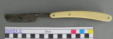
Sharped Edged instrument used for cleaning hair from the skin. http://en.wikipedia.org/wiki/Straight_razor A straight razor is a razor with a blade that can fold into its handle.[1] They are also called open razors and cut-throat razors. HISTORY The first modern straight razor complete with decorated handles and hollow ground blades was constructed in Sheffield, England, by Benjamin Huntsman in 1740. Huntsman's process was adopted by the French sometime later. The English manufacturers were even more reluctant than the French to adopt the process and only did so after they saw its success in France.[5] Straight razors were the most common form of shaving before the 20th century and remained that common in many countries until the 1950s. TODAY Straight razors are still manufactured. DOVO, of Solingen, Germany, and Thiers Issard of France are two of the most well-known European manufacturers. Feather Safety Razor Co. Ltd. of Osaka, Japan makes a razor with the same form as a traditional straight, but featuring a disposable blade that can be installed through an injector-type system. Modern straight razor users are known to favor them for a variety of reasons. Some are attracted to the nostalgia of using old and traditional methods of shaving. It is a masculine ritual comparable to pipe smoking. Others profess an interest in reducing the waste of disposable blades.[11][22] Still others agree that straight razors provide a superior shave through a larger blade and greater control of the blade including the blade angle. Straight razors cover a much greater area per shaving stroke because their cutting edge is much longer than any of the multiblade razors. Ivory cut throat razor, with cream case 00121.3.Known as a straight razor.Razor with square point, full hollow ground 5/8” blade and double transverse stabiliser. The centre pin adds stability and rigidity to the handle---I think this is it ROM Parts The narrow end of the blade pivots on a pin, between 2 pieces of ivory forms the handle. LONG EXTRACT FROM WIKI _ SHORTEN to describe 00121 The parts of a straight razor and their function are described as follows: The narrow end of the blade rotates on a pin called the pivot, between two protective pieces called the scales or handle. The upward curved metal end of the narrow part of the blade beyond the pivot is called the tang and acts as a lever to help raise the blade from the handle. One or two fingers resting on the tang also help stabilize the blade while shaving. The narrow support piece between the tang and the main blade is called the shank, but this reference is often avoided because it can be confusing. The shank sometimes features decorations and the stamp of the country of origin. The top side and the underside of the shank can sometimes exhibit indentations known as fluting, or jimps for a more secure grip.[8] The curved lower part of the main blade from the shank to the cutting edge is called the shoulder.[9] The point where the shoulder joins the cutting edge is called the heel. A thick strip of metal running transversely at the junction where the main blade attaches to the shank is called the stabiliser. The stabiliser can be double,[10] single or can be absent in some razor models. The first stabiliser is usually very narrow and thicker and runs at the shank to blade junction, covering the shank and just spilling over to the shoulder. The second stabiliser can be distinguished since it is considerably wider and narrower, appearing after the first stabiliser and running lower into the shoulder. The non-cutting top of the blade is called the back or the spine while the cutting part of the blade opposite the back is called the cutting edge.[11] Finally the other free end of the blade, at the opposite end of the tang, is called the point and, sometimes, the head or the nose.[9][12] There are two to three pins in any handle. The middle pin, if present, is plastic coated and is called the plug.[13] Its function is to stabilise the sides of the handle so that they cannot be squeezed in the middle. When folded into the scales, the blade is protected from accidental damage, and the user is protected from accidental injury. During folding, the back of the blade, being thick and normally with a curved cross-section, acts as a natural stopper and prevents further rotation of the blade out of the handle from the other side shaving, lever, handle, blade, pivot, razor, tang -
 Flagstaff Hill Maritime Museum and Village
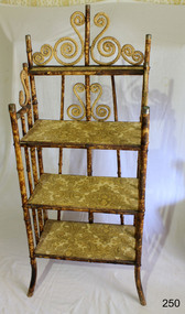
Furniture - Shelves, A. Englander & Searle, Late 19th Century (1898)
This music stand set of shelves is one of many 19th century items of furniture, linen and crockery donated to Flagstaff Hill Maritime Village by, Vera and Aurelin Giles. The items are associated with the Giles Family and are known as the “Giles Collection”. Many of the items of furniture, linen and crockery in the Lighthouse Keeper’s Cottage were donated by Vera and Aurelin Giles and mostly came from the simple home of Vera’s parents-in-law, Henry Giles and his wife Mary Jane (nee Freckleton) whose photos are in the parlour. They married in 1880. Henry, born at Tower Hill in 1858, was a labourer on the construction of the Breakwater before leaving in 1895 to build bridges in N.S.W. for about seven years. Mary Jane was born in 1860 at Cooramook. She attended Mailor’s Flat State School where she was also a student teacher before, as family legend has it, she became a governess at “Injemiara” where her grandfather, Francis Freckleton, once owned land. Henry and Mary’s family of six, some of whom were born at Mailor’s Flat and later children at Wangoom, lived with their parents at Wangoom and Purnim west, where Henry died in 1933 and Mary Jane in 1940. THE SHELVES During the years 1869-1935 there were well over 250 registered bamboo furniture producers in Britain. The earliest recorded firm was Hubert Bill of 14 Little Camden St, London N.W., who claimed to have been established in (1869 the first bamboo furniture maker), while Daniel Jacobs & Sons of Hackney Road, London, were still in business in 1915, after 45 years of production. Design, quality, price and methods of construction were fairly consistent throughout the whole period, but it was the imaginative and often eccentric choice of subject matter that marked the differentiation between the various firms. While most produced standard tables, stands and fire-screens, the more adventurous offered for sale items such as Corner shelve units, charcoal barbecue grills and musical tea tables. Shelves were often covered with embossed leather paper designs, at first imported from Japan and then later produced in England. Some firms incorporated the knobbly roots of the bamboo stems into their designs, generally to form feet. Occasionally handles to drawers and cupboards were made with these roots although they were more commonly carved as imitations. Handles were mostly of cheap metal or brass. The ends of the bamboo canes were capped with stamped metal or turned bone, ivory or wooden discs. Methods of construction fell into three categories. First and most common is that of pegging. Bamboo stems being hollow, thick dowels can easily be glued into the joints. Some firms farmed out this work of `plugging' the ends of the canes to part-time workers at home. The second method, that of pinning, was far less satisfactory as bamboo tends to split lengthwise and therefore the jointed pieces eventually disintegrated. The most efficient method was that patented in 1888 (patent No 2383) by the firm of W. F. Needham in Birmingham. It consisted of metal shoes and covers for all joints which were made by wrapping a metal strip around the stems and soldering the overlapping ends. Some joints were further strengthened by a small pin or screw. Needham was by far the largest and most successful manufacturer and their individual and superior method of construction undoubtedly gained them their reputation. A. Englander & Searle of 34 Gt Eastern St and 31 Mare St, Hackney, London, were a firm particularly concerned with methods of construction. Although they seem to have entered the bamboo furniture market at a comparatively late date, about 1898, they produced inexpensive bamboo, aimed particularly at the export trade. The company stated in their catalogue that bamboo furniture “can be exported in one piece or it can be exported in pieces and put together again. The fixing up is much facilitated by a system of marking and numbering. Further, no glue is required for putting together as the screw system only is applied”. This method of construction best fits the Etagere in the Flagstaff collection and it is believed to have been made by A Englander & Searle, exported in a knock down form to Australia, purchased in kit form from a dealer hear and put together by the owner. The Etagere is a significant item as it highlight furniture fashion of the late Victorian era. This item was highly sort after in its time and although mass produced, not many examples remain, so this example is a valuable addition to the Flagstaff collection. It is believed that the construction method used is by a notable and respected maker of bamboo furniture and that its production was aimed at the export market and probably came to Australia in kit form.Bamboo shelves: decorative free standing Etagere comprising three large shelves and one small shelf. Shelves are made of wood used to store either orange or bacon boxes (as there are no knots in the wood, imported from South America and cheap to recycle). Shelves are covered with embossed leather paper. Frame is made from tortoise shell bamboo (brown lacquer applied to simulate tortoise shell appearance). Ends of bamboo canes are covered with metal shoes and fixed with a pin. Other bamboo joints are fixed with round head steel screws. This item is part of the Giles Collection.Noneflagstaff hill, warrnambool, shipwrecked-coast, flagstaff-hill, flagstaff-hill-maritime-museum, maritime-museum, shipwreck-coast, flagstaff-hill-maritime-village, bamboo shelves, bamboo etagere, victorian furniture, furniture, bamboo furniture, embossed leather paper, simulated bamboo, tortise shell, a englander & searle, giles collection, henry giles, tower hill, cooramook, warrnambool breakwater, mailor’s flat, wangoom, 19th century furniture -
 Flagstaff Hill Maritime Museum and Village
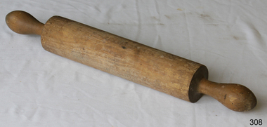
Domestic object - Wooden Rolling Pin, First half of 20th Century
A rolling pin is a simple tool used to flatten dough. The first civilisation known to have used the rolling pin was the Etruscans. Their advanced farming ability, along with a tendency to cultivate many plants and animals never before used as food and turn them into sophisticated recipes, were passed to invading Greeks, Romans, and Western Europeans. Thanks to the Etruscans, these cultures are associated with gourmet cooking. To prepare their inventive foods, the Etruscans also developed a wide range of cooking tools, including the rolling pin. Although written recipes did not exist until the fourth century B.C., the Etruscans documented their love of food and its preparation in murals, on vases, and on the walls of their tombs. Cooking wares are displayed with pride; rolling pins appear to have been used first to thin-roll pasta that was shaped with cutting wheels. They also used rolling pins to make bread (which they called puls) from the large number of grains they grew. Natives of the Americas used more primitive bread-making tools that are favoured and unchanged in many villages. Chefs who try to use genuine methods to preserve recipes are also interested in both materials and tools. Hands are used as "rolling pins" for flattening dough against a surface, but also for tossing soft dough between the cook's two hands until it enlarges and thins by handling and gravity. Tortillas are probably the most familiar bread made this way. Over the centuries, rolling pins have been made of many different materials, including long cylinders of baked clay, smooth branches with the bark removed, and glass bottles. As the development of breads and pastries spread from Southern to Western and Northern Europe, wood from local forests was cut and finished for use as rolling pins. The French perfected the solid hardwood pin with tapered ends to roll pastry that is thick in the middle; its weight makes rolling easier. The French also use marble rolling pins for buttery dough worked on a marble slab. Glass is still popular; in Italy, full wine bottles that have been chilled make ideal rolling pins because they are heavy and cool the dough. Countries known for their ceramics make porcelain rolling pins with beautiful decorations painted on the rolling surface; their hollow centres can be filled with cold water (the same principle as the wine bottle), and cork or plastic stoppers cap the ends. Designs for most rolling pins follow long-established practices, although some unusual styles and materials are made and used. Within the family of wooden rolling pins, long and short versions are made as well as those that are solid cylinders (one-piece rolling pins) instead of the familiar style with handles. Very short pins called mini rolling pins make use of short lengths of wood and are useful for one-handed rolling and popular with children and collectors. Mini pins ranging from 5 to 7 in (12.7-17.8 cm) in length are called texturing tools and are produced to create steam holes and decorations in pastry and pie crusts; crafters also use them to imprint clay for art projects. These mini pins are made of hardwoods (usually maple) or plastic. Wood handles are supplied for both wood and plastic tools, however. Blown glass rolling pins are made with straight walls and are solid or hollow. Ceramic rolling pins are also produced in hollow form, and glass and ceramic models can be filled with water and plugged with stoppers. Tapered glass rolling pins with stoppers were made for many centuries when salt imports and exports were prohibited or heavily taxed. The rolling pin containers disguised the true contents. The straight-sided cylinder is a more recent development, although tapered glass pins are still common craft projects made by cutting two wine bottles in half and sealing the two ends together so that the necks serve as handles at each end.Tiny rolling pins are also twisted into shape using formed wire. The pins will not flatten and smooth pastry, and the handles do not turn. The metal pins are popular as kitchen decorations and also to hang pots, pans, and potholders. https://www.encyclopedia.com/sports-and-everyday-life/food-and-drink/food-and-cooking/rolling-pinThe use of the rolling pin to make thin pastry or pasta.Wooden rolling pin with some damage on cylinder section.None.flagstaff hill, warrnambool, shipwrecked-coast, flagstaff-hill, flagstaff-hill-maritime-museum, maritime-museum, shipwreck-coast, flagstaff-hill-maritime-village, rolling pin, cooking, pastry -
 Melbourne Legacy
Document - Speech, Moments in the History of Legacy 1987 (H59), 1987
A copy of an address given at a Foundation Day Luncheon by a long standing Legatee and past President Legatee Rob Allison. He had joined Legacy in 1950, and he comments that only 5 members remain active that were with him in 1950. In 1950 they were all posted as member of various committees, he got Welfare and Friday night girls' classes. There were 9 boys' classes throughout Melbourne, and girls' twice a week at Legacy Headquarters at 24 Market St. There were 230 active members and each legatee had 4 or 5 families with children. He mentions that in 1950 the President was 62 years old but only 5 years after the end of the war, the tide had begun to turn towards the 39ers. (He called the older legatees '1914ers' or 'the Bow and Arrow boys'). He applauded the 'founding fathers' for limiting the numbers of members, in 1929 it was 230 and in 1959 a limit of 300. They used a classification method to classify the members so they had a diverse range of skills and community representation. Areas were: Production, Distribution, Services Public Authority, Services Other, and Board List. The President had a Secret Committee of 3, no one knew who was on the committee, even those members didn't know the identity of the other 2. This committee vetted the background and integrity of new members. In 1950 the budget was £27,000 plus a capital budget of £3,500. Legatee Allison tells a good story of his induction into Legacy, including his wife joining other Legatees wives in fundraising. In 1951 Comradeship meetings moved to Thursday nights at the instigation of Burt Nathan. 'Birthday boy' invitations started in 1958 when John Cooper was Chairman of the Comradeship. After some years of discussion the first paid Social Worker was employed in 1953 and as a result her efforts the first Senior Widows' Group got underway. Until the 1950s Legacy had always found the money it required, from big companies, wealthy members of the community, Estates, or Trusts. In 1951 it tried to copy a Sydney Legacy idea (Certificate of Adoption Plan) and called it 'The Endowment Scheme'. Other fundraisers included films, premiere showing and musicals were very much a part of the social life of Legatees. One premiere show in 1952, 'The Greatest Show on Earth' was sold at £100 a double. In 1959 Sir Frank and Lady Tait were kind enough for give us a premiere of 'My Fair Lady'. As the 50s progressed cash flow was not enough and it was decided in 1957 to have the first public appeal (he says 1957 but it was 1956). The first Badge day was 1958 (according to this account). He says it grossed £21,000 (net £17,000). And the Legacy story was becoming better known. 'Legacy has never been a one man band. The strength has been in the resourceful ability of those of its members.' He was well placed to tell the story of the donation towards Dureau House. BG Corporation in New York used 'Brown and Dureau' as agents in Melbourne for their spark plug manufacturing (for the American aircraft based in Australia during the war). A royalty of two shillings and sixpence was agreed. The entrepreneur President of BG Corporation was Richard Goldsmith. L/ Grat Grattan had a friend Mr Edwards who was managing director at Brown and Dureau and heard of the desire by Goldsmith to leave a permanent memorial to ex-servicemen in Australia (Children's Hospital was considered). Grat took Edwards to Market St and showed him the inadequacy of the building. It was agreed if Melbourne Legacy could come up with a purchased building in 10 days they would get the money needed. The property purchased was 'Storey Hall' in Swanston St (also called Hibernian Hall in other documents). After the war it turned out not to be suitable and a new building was required. The speaker is identified as Rob Allison based on two things; at one stage he refers to himself as 'Rob' and this copy of the speech has been faxed to Legacy from the offices of John Allison Monkhouse. Another copy of this address has been located with the date of September 1988 that was filed with information on Past Presidents and the lives prominent legatees. The notation H59 in black pen shows that it was part of the archive project that was trying to capture the history of Legacy. A record of Legatee Rob Allison speaking at a Legacy luncheon about significant events since he joined in 1950. Speakers at Legacy luncheons were from very different walks of life and the subjects spoken on were many and varied. Foundation Day was celebrated with a special luncheon.White A4 photocopy with black type x 8 pages of an address about Legacy history written in 1987.Handwritten H59 in black pen. history, speech, foundation day, past presidents, dureau house, rob allison -
 Eltham District Historical Society Inc
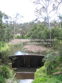
Photograph - Digital Photograph, Marguerite Marshall, Smith Dam, Karingal Drive, Eltham, 19 September 2006
The dam at the entrance to the Nerreman Gateway in Eltham was built according to an internationally acclaimed theory developed by the builder's father. In 1920, Victorian engineer B.A. Smith was awarded the American Society of Civil Engineers J. James R. Cross Gold Medal for his Technical Paper titled 'Arched Dams'. It was the first time this medal had been awarded outside the United States. The concrete arched dam across the Eltham West Drain was built in 1940 by B.A. Smith's son and engineer, D. B. (Bernie) Smith to water the 24 acre (9.75 ha) hobby farm owned by himself and new wife, Isa Smith. Upon completion of the dam a pump-house was constructed beside the creek but before the water could be pumped up the hill they had to dig a trench and lay 500m of 100mm water main to an elevated holding tank. The Smiths made the pump-house their home for several years until they constructed their home at the top of the hill overlooking Eltham and views extending to Kinglake. Following Bernie's death in 1983, Nerreman Park was subdivided between 1993 and 1995. Gordon Ford designed the landscaping and the pump-house was demolished. Covered under Heritage Overlay, Nillumbik Planning Scheme. Published: Nillumbik Now and Then / Marguerite Marshall 2008; photographs Alan King with Marguerite Marshall.; p137 The dam at the entrance to the Nerreman Gateway in Eltham, was built according to an internationally acclaimed theory developed by the builder’s father. In 1920, Victorian engineer B A Smith was awarded the American Society of Civil Engineers J. James R. Croes Gold Medal, for his Technical Paper titled Arched Dams. It was the first time this medal had been awarded outside America. An international example of the application of Smith’s work can be found in the design of the Hoover Dam on the Colorado River, Nevada, USA. Built between 1930 and 1936, it is recognised by the ASCE as one of ‘America’s Seven Modern Civil Engineering Wonders’.1 The concrete arched dam across the Eltham West Drain was built by B A Smith’s son and engineer, D B (Bernie) Smith. Bernie’s dam followed his father’s theory, having a curvature that takes maximum advantage of concrete’s great strength in compression. The water load is carried into the abutments because of this curvature, which permits a wall thickness of only 225 millimetres thick at its crest, despite the dam’s capacity of more than 4.5 megalitres. The Eltham dam was designed to water the 24 acre (9.75 ha) hobby farm belonging to newly married couple Bernie and Isa Smith. Bernie, from Armadale, and Isa, from a farm at Tyntynder near Swan Hill, were attracted to the hilly topography and the creek running through the property. It extended from Ryans Road, Eltham, to Karingal Drive, Montmorency and was adjacent to Meruka Park. The Smiths named it Nerreman Park using the Aboriginal word Nerreman meaning ‘River Bend’ as their creek had a pronounced bend.2 In 1940 the first thing Bernie did was to build a dam, and with Isa’s help, a pump-house, to secure a water supply for their cattle, pigs, chickens, orchard and vegetable gardens. It was also available for the fire-plugs, which they placed all over the property in case of bushfire. The couple built the pump-house beside the creek and installed a Tange three-plunger pump, which had originally supplied the City of Wodonga with water. But before the Smiths could pump water up the hill from the dam they had to dig a trench and lay about 550 yards (500m) of a four-inch (100mm) water main up to an elevated holding tank. The trench was dug with a single furrow plough drawn by an old draught horse. Living in rough conditions did not deter the Smiths, who made the pump-house their home, where they still lived when their first child was born in 1944. They later built their home at the top of their property overlooking Eltham, with magnificent views to Kinglake, the Dandenong Ranges and Melbourne. From 1946 it took them almost 20 years to complete the 36-square house with its 12-foot (3.6m) high ceilings. Material for the concrete roof and walls faced with sandstone, was ripped out of the ground on their property by plough pulled by tandem Clydesdale horses. Isa was a strong woman – two days before their second child was born – she set three huge sandstone boulders in place in the bottom wall of the garage. She also mixed all the cement for the house. A collapsed kitchen wall did not discourage her from rebuilding it in a week, while her husband was away working in the country. She later recalled: ‘We stood back to admire this beautiful wall we’d built and while we were looking at it, it came tumbling down’.3 Following Bernie’s death in 1983, Nerreman Park was subdivided, between 1993 and 1995. Local Gordon Ford designed the landscaping and the pump-house was pulled down. But the dam remains as a reminder of exceptional engineering4 – and of a remarkable couple.This collection of almost 130 photos about places and people within the Shire of Nillumbik, an urban and rural municipality in Melbourne's north, contributes to an understanding of the history of the Shire. Published in 2008 immediately prior to the Black Saturday bushfires of February 7, 2009, it documents sites that were impacted, and in some cases destroyed by the fires. It includes photographs taken especially for the publication, creating a unique time capsule representing the Shire in the early 21st century. It remains the most recent comprehenesive publication devoted to the Shire's history connecting local residents to the past. nillumbik now and then (marshall-king) collection, eltham, karingal drive, smiths dam, bernie smith, gordon ford, isa smith, nerreman gateway, nerreman park estate, dams -
 Federation University Historical Collection
Object, Synchronome Co. Ltd, Synchronome Frequency Checking Master Clock No. 2191, c1930
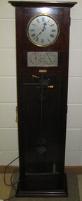
Information from Norman F. Dalton: Ballarat had a reticulated DC supply in the early part of last century and in 1905 had sufficient generating capacity to enable the trams to be changed from horse drawn to DC electricity. The use of electricity increased with the main power station located on Wendouree Parade, near Webster Street, under the ownership of The Electric Supply Company of Victoria. AC generating plant was installed in 1925 and conversion to AC proceeded. In 1934 the company was taken over by the State Electricity Commission Victoria (SECV) and more AC generation was installed and the changeover of customers was accelerated. This is around the time that the Synchronome Frequency Checking Mast Clock was installed at the Wendouree Parade Power Station. The SECV Annual Report of 1921 states: ::Section 11 of the act directed the COmmission to enquire into the question of securing the adoption of such standards of plant and equipment of a system, frequency and pressure for the generation and distribution of electricity as will admit of the efficient interconnection of undertakings throughout the State. In 1934 when the SECV took over the Ballarat operations the question of linking with the State grid had been a planned operation for some years but due to financial considerations had hindered it and in fact would continue to do so for a further 10 years. So while the need for close frequency control for interconnection was hardly an issue, the need to keep electric clocks correct was important, particularly as this item was a frequent sales point to cover the inconvenience and sometimes expense of converting from DC to AC. The clock is a very accurate pendulum clock with provision for varying effective length during operation for precise time regulation. There are two normal time dials and one is controlled by the pendulum and the other is operated by the system frequency. When the clock was in use it was installed by the MEter and Tests Laboratory and the time was checked daily by radio time signals. The two dials were repeated in the operators control panel in the Power Station. A maximum deviation between the two dials was set in the operating instructions (eg 5 seconds) and the operator would correct this when necessary by remote manual alteration of the turbine governor set point. The clock was used to drive and regulate a system of "slave" clocks which were used to display the time in various locations around the power station. A slave clock is a simple clock which is driven by a small electric motor, its accuracy is regulated by the master clock every 30 seconds to ensure that it and all the other slave clocks in the station are on exactly the right time; slave clocks were placed in various locations, from common rooms to workshops. A master clock could potentially run thousands of slave clocks at one plant. The clock also contains a rectifier. A rectifier is a device that is used to convert AC power to more stable DC current.Two clocks in a timber case. Both are electric, one is powered by the main pendulum mechanism, the other is a self contained electric clock. The main mechanism is of the gravity arm and roller type, which sends an impulse to the slave clocks every 30 seconds. The This Synchronome Frequency Checking Master Clock was used at the Ballarat Power Station. Below the main section of the case is a smaller cabinet containing a rectifier to provide consistent DC power for the clock. The rectifier was made by the Victorian company Hilco, which was located in Burwood. There is a high chance this is not the original rectifier from this clock as there appears to be brackets to hold a larger device in the space the rectifier occupies.Front below main clock face on front of case: "Patented Sychronome Brisbane" Lower left-hand clock face: "Frequency time" Lower right-hand clock face: "Standard Seconds" Synchronous electric clock mechanism on door (Frequency time clock): >200/250 V. 50~ >"Synchronomains" Made in England >Direction indicator for clock starting switch >"To start move lever in direction of arrow and release" >"Patent applied for" Mechanism for "standard seconds" clock: >"English Made" >"Patented" >Serial number "321" >0 above right-hand pillar on front-plate Mechanism for "standard seconds" clock: >"English Made" >"Patented" >Serial number "321" >0 above right-hand pillar on front-plate Mechanism for main clock face: >"English Made" >"Patented" >Serial number "8751" >0 above right-hand pillar on front-plate Inside case, back panel, top enamel plate: >Seconds Battery + Pos. > Battery Common or - Neg. >1/2 min dials Inside case, back panel, bottom enamel plate: external seconds dial Inside case, right hand side, electrical knobs: two switches, both "A.C. mains" Pendulum rod, below suspension spring: Serial number (?) 0000005 Rectifier in bottom cabinet: >"Hilco Rectifier" >"A.C. Volts 230/240" >"Model 1060/S" >"A.C. Amperes" >"Serial No. 1060/S >"Phases 1" >"D.C. Volts 6" >"C.P.S. 50" >"D.C. Amperes 1" >"Made in Australia by Hilco Transformers McIntyre St., Burwood, Victoria." Bakelite electrical plug: makers mark Lower cabinet, RH side panel, pressed tin plate: "AC" (upside down) Brass speed adjustment, outer right RH side: "S" and "F" Ivory and wood pendulum beat ruler: >Ruler, with 0 in centre and numbers 1-5 in ascending order from centre on left and right. > "Synchronome Patent." Steel plate, back panel, inside case, right hand side: >N R A" (descending) >"2191" serial number/part number Face of main clock: "Synchronome Electric" synchronome frequency checking master clock, electricity, state electricity commission, wendouree parade power station, secv, clock, time, pendulum, electric supply company of victoria, norman f. dalton, ballarat power station, rectifier, slave clock -
 Bendigo Military Museum
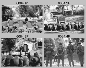
Photograph - Army Survey Regiment - Regimental Training Military Skills Revision, 1985
This is a set of 35 photographs of the Army Survey Regiment personnel undertaking military skills revision, at the Army Survey Regiment, Fortuna, Bendigo, 1985. They participated in lessons on the handling of the M30 Grenade and SLR Rifle. These lessons were part of the six objectives of regimental training outlined in the administrative instruction – Exercise “City Soldier” accompanying these photos. The other objectives were first aid at Fortuna, RATEL and navigation at Wellsford Forest; and rifle shooting at Wellsford Rifle Range. Personnel from Air Survey, Cartographic, Lithographic and Headquarters Squadrons were reallocated to four training platoons for one week from 7th to 11th October 1985.This is a set of 35 photographs of the Army Survey Regiment undertaking military skills revision, part of Regimental Training at Fortuna Villa 1985. Black & white photos .1P to .17P are printed on photographic paper and scanned at 300 dpi. Photos .18P to .35P are on 35mm negative film and scanned at 96 dpi. They are part of the Army Survey Regiment’s Collection. .1) - Photo, black & white, 1985, L to R: CPL Brian Fauth, unidentified (x2), SGT Dennis Learmonth - instructor, unidentified (x2). .2) - Photo, black & white, 1985, unidentified personnel, SGT Dennis Learmonth – instructor. .3) - Photo, black & white, 1985, unidentified personnel, SGT Dennis Learmonth – instructor. .4) - Photo, black & white, 1985, unidentified personnel, SGT Dennis Learmonth - instructor. .5) - Photo, black & white, 1985, unidentified personnel. .6) - Photo, black & white, 1985, unidentified personnel. .7) - Photo, black & white, 1985, L to R: SGT Dennis Learmonth – instructor, CPL Brian Fauth, SPR Viv (Hawkins) Doherty, CPL Ken Peters, CPL Megan (McBurney) Reynolds, CPL Mick ‘Buddha’ Ellis, unidentified, SPR Wally Twidale, unidentified personnel. .8) - Photo, black & white, 1985, L to R: unidentified personnel, LT Ossie Slade. .9) - Photo, black & white, 1985, L to R: unidentified personnel, CPL Greg Honan, SGT Don Williams, LCPL Bob Sheppard, unidentified personnel. .10) - Photo, black & white, 1985, L to R: unidentified personnel, SPR Bloxham, SPR Jason Wells, unidentified personnel, CPL Gillham, CPL Peter Imeson, unidentified. .11) - Photo, black & white, 1985, L to R: SPR Terry Winzar, unidentified, WO1 Noel ‘Nesty’ Coulthard, unidentified personnel. .12) - Photo, black & white, 1985, unidentified personnel. .13) - Photo, black & white, 1985, L to R: SSGT Tony Harder – UK Exchange Instructor, unidentified personnel, CPL Bob Thrower, unidentified, SPR Jim Humphrey, LCPL Bob Sheppard. .14) - Photo, black & white, 1985, L to R: unidentified personnel, CPL Mark Casey, SSGT Tony Harder – UK Exchange Instructor. .15) - Photo, black & white, 1985, L to R: unidentified, CPL Paul Richards, SPR John Keely, CPL Peter Johnson, unidentified, SSGT Tony Harder – UK Exchange Instructor, SPR Dave Wright, unidentified personnel. .16) - Photo, black & white, 1985, L to R: unidentified, WO2 Brian Partridge – Instructor, unidentified personnel. .17) - Photo, black & white, 1985, WO2 Brian Partridge – Instructor, unidentified personnel. Unidentified. .18) - Photo, black & white, 1985, CPL Lea-anne (Smallshaw) Shirley, CPL Megan (McBurney) Reynolds, SGT Dennis Learmonth – instructor. .19) - Photo, black & white, 1985, SSGT Steve Hansen – Instructor, from background tree L to R: SPR Dave Lawler, CPL Ken Peters, CPL Steve Burke, SPR Wally Twidale, CPL Dave Murphy, SPR Jim Walker. .20) - Photo, black & white, 1985, L to R: unidentified (x3), CPL Ian Nelson, CPL Eddy Jacobs, SPR Tracy (Parker) Ash, remainder unidentified. .21) - Photo, black & white, 1985, CPL Eddy Jacobs piggybacking SPR Jason Wells, remainder unidentified. .22) - Photo, black & white, 1985, CAPT Dave McLachlan piggybacking unidentified soldier. .23) - Photo, black & white, 1985, unidentified soldiers competing in leapfrog race. .24) - Photo, black & white, 1985, SPR Leah (Hoffman) Peppler throwing dummy hand grenade, SSGT Ian ‘Rock’ Thistleton – Instructor. .25) - Photo, black & white, 1985, unidentified soldiers’ basic pouches cleared by instructor at end of hand grenade lesson. .26) - Photo, black & white, 1985, unidentified soldier throwing dummy hand grenade. .27) - Photo, black & white, 1985, unidentified personnel with dummy hand grenades, SGT Dennis Learmonth – instructor. .28) - Photo, black & white, 1985, unidentified soldier throwing dummy hand grenade. .29) - Photo, black & white, 1985, unidentified personnel with dummy hand grenades, unidentified instructor. .30) - Photo, black & white, 1985, adjusting SLR rifle gas plugs L to R: unidentified, SPR John Keely, CPL Paul Richards, unidentified, CPL Peter Johnson, remaining personnel unidentified, unidentified instructor. .31) - Photo, black & white, 1985, L to R: unidentified (x6), SPR Dave Wright, unidentified, SPR Barry Hogan, CPL Lyall Camp, SSGT Tony Harder – UK Exchange Instructor, SPR Steve Coulson, CPL Mark Lander. .32) - Photo, black & white, 1985, SLR rifle lesson L to R: unidentified, CPL Gary Drummond, SSGT Steve Hansen – Instructor in background, CPL Peter Breukel, SPR Steve Burke, CPL Brian Fauth, remaining personnel unidentified. .33) to .35) - Photo, black & white, 1985, unidentified personnel during SLR rifle lesson..1P to .35P No personnel are identifiedroyal australian survey corps, rasvy, army survey regiment, army svy regt, fortuna, asr -
 Ballarat Tramway Museum
Manual, Doug Prosser, "General Electric Data for Car Equipment Maintenance", 1998
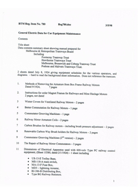
A black plastic folder containing a set of 38 General Electric Data Sheets for MMTB and tramway trust equipment, dated July 8 1924. Contained in folder with flexible clips. Pages have been punched with four holes. Copy of document made for BTM Feb 1998 by Doug Prosser. For scan of list - see btm780sheet.pdf General Electric Data for Car Equipment Maintenance Contents For scan see btm780d1 (5 pages) Title sheet Data contents summary sheet showing manual prepared for Melbourne & Metropolitan Tramways Board Including Footscray Tramway Trust Hawthorne Tramways Trust Melbourne, Brunswick and Coburg Tramway Trust Prahran and Malvern Tramways Trust. 2 sheets dated July 8, 1924 giving equipment schedules for the various operators, and diagrams. - hard to read the background sheet information. Does not reference the tramcars. For scan see btm780d2 (54 sheets - items 1 to 27) 1. Methods of Removing the Armature from Box Frame Railway Motors Dated 9/1924, 7 pages 2. Instructions for order Magnet Frames for Railways and Mine Haulage Motors 2 pages, not dated 3 Winter Covers for Ventilated Railway Motors - 2 pages 4 Better Commutation for Railway Motors - 1 page 5 Commutator Grooving Machines - 1 page 6 Railway Motor Armature Coils - 2 pages 7 Carbon Brushes for Railway motors - including brush pressure adjustment - 2 pages 8 Renewable Carbon-Way Brush holders for Railway Motors - 2 pages 9 Commutator Grooving Machines (2nd version) - 2 pages 10 The Repair of Railway Motor Commutators - 3 pages 11 Dimensions of Electrical Apparatus used with 600-volv Type PC railway control equipment, (Sheet 15380, dated 2/1/1924) - 1 sheet including · US-13-E Trolley Base, · MS-118-A main switch, · MA-13-F Fuse Box, · MD3 - lightning Arrester, · BJ-386-B Distributing Box, · Type BG Railway Resistors. 12 Connections of Type KM-63-BR Railway Controllers and Equipment - Drawing 15257, 1 page, dated 1/3/1921 with dimension details on rear of type K-63-BR railway controller equipment including: · SG Resister, · BK-13-A Insulator, · MR11 - Circuit breaker, · MD3 - Lightning Arrester box, · K63-BR Controller, · US15C Trolley Base. 13 Method of Supporting Railway Resistors using Porcelain Bolt insulators for 600 and 1500 Volt Work. Drawing dated 1/11/1923, No. 15249B - 1 page 14 Dimensions of Electrical Apparatus used with 600-volv Type M railway control equipment, (Sheet 15381, dated 2/1/1924) - 1 sheet including · US-13-E Trolley Base, · MS-118-A main switch, · MA-13-F Fuse Box, · MD3 - lightning Arrester, · BJ-386-B Distributing Box, · Type BG Railway Resistors. 15 Dimensions of Electrical Apparatus used with 600Volt, Type PC Railway Control Equipment. Drawing No. 15382, dated 2/1/1924. Includes: · C129-A Master Controller, · DA82C Coupler sockets, · MS-14-G switch, · MS-46-H switch. 16 Dimensions of Electrical Apparatus used with 600-volv Type M railway control equipment, (Sheet 15383, dated 2/1/1924) - 1 sheet including · C-169-A Controller · DA-69-B Coupler Socket and DC-66-C Coupler Plug · MS-14-G Switch · MS-46-H-Switch 17 Method of Making Tap Connections for Car Cables -= SD 15468, 1/11/1924, 1 page 18 The Repair of 600 Volt Railway Motor Armatures, 64408, 9/2/1924, 4 pages 19 Proper Method of Mounting and Dismounting Railway Motor Pinions. - 2 pages 20 Pinion Pullers for Railway Motors - 2 pages, dated 8/1/1924. 21 The Care of Railway Motor Bearings - 4 pages 22 Oil Scraper Rings for Air Compressors - 64590 - May 1924 - 1 page 23 Finger Bases for type K 63 controller 1 page 24 Adjustment of Drum Controller fingers - 29/1/1924, 64600A - 1 page 25 Star Wheels for Type K Controllers - 64603 - 1 page 26 Soldering Aluminium Controller Cylinder Castings - 2 pages 27 Porcelain Bolt Insulators for Railway Service - and drawing on rear showing mounting arrangement of resistor Grids - 2 pages. For scan see btm780d3 (13 pages) 28 Connections of Armature and Field Winding for GE-201-F and GE 263A railway motors. DS37869 29 Connections of Armature and Field Winding for GE-201-I railway motors. K1629303 30 Connections of Armature and Field Winding for GE-202 motor, DS 10472 31 Connections of Armature and Field Winding for GE-203 A and GE 226 railway motors. DS23869. 32 Connections of Armature and Field Winding for GE-241 motors - K1629077 33 Connections of Armature and Field Winding for CP25A Air compressor 34 Connections of Armature and Field Winding for CP27A Air compressor 35 Connections of Armature and Field Winding for GE-258 and GE 264 railway motors. K1629343. 36A- Dimensions of Type K-63-BR Railway Controller Equipment 36 US-13-E Trolley Base for Railway Service - 3/1/1923, 64823 - 2 pages 37 Copy of M&MTB (Eastern System) Certificate of Competency as Motorman. 38 Photocopies of a series of four photos of 22E trucks under an SEC tramcar. For scan see btm780d4 (40 pages) 39 Sprague G-E Multiple Unit Control, Type PC, Instruction Book 84772 - Oct. 1922 - 40 Pages. Images of sheets added 2-11-15 trams, tramways, general electric, motors, controllers, trolley pole bases -
 Ringwood and District Historical Society
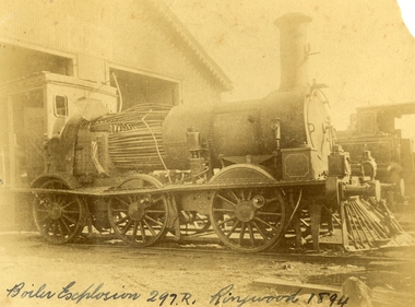
Photograph, Boiler explosion at Ringwood station 20th June 1894 for engine 297R. "Heard in Box Hill"
Black and white photographs - 2 copiesTyped below photograph, "Boiler explosion at Ringwood station 20/6/1894. Heard in Box Hill". Article from newspapers:- Weekly Times (Melbourne, Vic. : 1869 - 1954), Saturday 27 January 1894, page 21 Official enquiry. The Board of Enquiry appointed by the Railway Commissioners to enquire into the causes of the boiler explosion which shattered the locomotive at Ringwood on Saturday night, assembled at the Railway department on Wednesday to commence its deliberations, The board consisted of Mr R. Fulton, engineer, C. W. McLean; engineer to the Marine Board, and Mr Mephan Ferguson, iron-founder. There is some difficulty at the outset about the constitution of the board; It was suggested that the Apt of Parliament contemplated that boards of experts, after the manner of the present one, needed, to have their appointments confirmed by the Governor-in-Council. The point, however, was not considered sufficiently important to prevent the board from proceeding with evidence. Robert Greyford, stationmaster at Ringwood, was the first witness. He said he saw the explosion on Saturday night at about twenty minutes to 8. There was a rush to the engine to see what had happened, and the driver and fireman were both found on the platform of the engine. The driver seemed badly hurt, but the fireman, to all appearances, was not so badly injured. They were both attended to and sent up to Melbourne by the last suburban train. Witness had a look at the engine and found the dome and all the plates round the boiler blown clean, away. The springs were also blown clean away. The Chairman (Mr Fulton) : Did you measure the distance ? Witness: Yes; one of the plates was 209 yards away. A piece from the top of the boiler 15 pounds in weight he found driven into the hard beaten track 410 yards away. Several pieces of boiler plate were found scattered at various distances. The buildings roundabout were injured. The Chairman; Did you notice anything peculiar about either of the driver or the fireman ? — No ; nothing wrong, with either of them. If the engine was blowing off at all, it must have been very light. In your opinion, were they perfectly sober ? — Perfectly. In approaching the station, is there a down or an up grade? — A very slight down grade. How is the road from Healesville ? — Up and down all the way. It is down, grade for about 200 yards coming into Ringwood station. They shut off ; steam about a quarter of a mile away, and come in at a good pace. They generally put on 15 pounds of steam while they are in the station. Mr Ferguson : Had the driver the usual load on ? — Yes ; about the usual load. Witness added that he had known the driver personally for about 10 years, and he had always been a careful, steady, sober man. He did not know the fireman so well. John Palmer, porter at Ringwood station, also saw the explosion. He was attending to the train on its arrival. He was knocked down by the force of the explosion. When he got up he saw the engine driver being carried into the office covered in blood. He noticed nothing peculiar about the driver and fireman, nor about the engine. Mr McLean : How far were you from the engine when you were knocked down ? — From ten to fifteen yards. William Paul, the guard of the train to which the injured locomotive Was attached, said he was looking at the engine at the very moment the explosion occurred. It seemed to come from exactly under the dome. The force of it took him off his feet. He was about 15 yards from the tender. When he rose he tried to reach the engine, but could not do so on account of the steam and coal dust. He called out to know whether any of the passengers were injured, and got no response, so that he concluded they were all right. All the lamps but about half dozen were extinguished by the force of the explosion, although the glass was not broken. He could testify most distinctly that the driver and fireman were both sober. The driver was a man who never drank. The steam started to blow off about a minute and a half before the explosion took place. The last place at which the engine took water was Healesville. The Chairman : Do yon know anything of the quality of the water there ? Is it creek water ? — Yes ; it comes from the Graceburn River. You never heard of its quality ?— No. How long have you known this engine on the road— About 13 months. Hew long have you known the driver on this line ? — About six weeks. I have known the fireman several years. The driver was a strict teetotaller, and I never saw the fireman take anything to drink in his life. Mr T. H, Woodroffe, chief mechanical engineer of the Victorian Railways, produced a report he had written to the secretary, about this explosion. The document gave facts concerning the engine and the explosion. It stated that the rapture seemed to have occurred at the rim of the plates adjoining the fire box. The engine was built at the Phoenix Foundry, Ballarat, in 1883. It was repaired at various times, the last time being in July of last year when it was sent to the Port Melbourne shops, and was then tested to a cold water pressure of 195 and found all right. It was the custom to overhaul all locomotives about every five years. The Chairman : There were no very heavy repairs in July, 1893; were there? — Not to the boilers. The shop manager's report says that the plug and safety tap holes were repaired, five new copper studs put in firebox, ash-pan door repaired, tender cleaned and overhauled, and studs re-rivetted, and boiler tested to pressure of 195, cold water. Mr Woodroffe read the report of the repairs effected to the boiler in December, 1888. That would be the time the plate was put in the boiler. On that occasion three new plates were put in the bottom and the boiler tested up to 195. The Chairman: Do you keep a record of the water used ?— Yes, the water in this case, I think, came from the Maroondah scheme. Mr Woodroffe said boilers were examined front time to time in the running sheds. In his opinion every possible care had been taken to keep the engine in proper care. There might, however, be lessons learnt from this. The Chairman: No doubt. From his examination of the plates [the] witness did not think the state of them could have been detected from the outside. There were no signs of leakage or sweating or anything of that sort. The next witness- was Walter Stinton, workshop manager at Newport and he said that the injured engine had been repeatedly repaired under his charge. He gave a technical account of the repairs effected on various occasions. The testing of locomotives was under his special notice. They had a high pressure pipe running; round the works, and a pump set at 2001b. When the boiler was pumped full of water the pressure when applied up to 1951b. The board appointed by the department to inquire into the Ringwood locomotive boiler explosion sat again at Spencer street on 25th inst. Mr R. Fulton presided and the other members of the board were. Mr Mephan Ferguson and Mr C. W. McLean. Charles Grubb, foreman of the boiler-makers at the Newport workshops, said he had inspected the pieces of plate that had been blown out of the engine, and after examining them, pointed out to the Chief Mechanical Engineer the portion where the plate had started to burst. It was under the lap, on the right hand side of the boiler. The grooving might be accounted for by bad water. During the past twenty years he had examined all the boilers that came into the Williamstown workshops, and while some were hardly marked at all, others were very badly eaten away. The practice was to cut out the defective portions. In this case the boiler was repaired in a similar manner. The Chairman : Can you suggest any other way of repairing so as to prevent accident ? — No, unless by taking out a plate on one side from the joint, and carrying it further up so as to avoid the joints meeting, or by taking out the plate altogether. What would.be the cost .of putting in a new " plate I—Perhaps about double the price; but I wouldn't recommend that course. It would be putting a new plate against plates that have been in use ten years or so and that would not be advisable. I think the present system better. I consider the present system of repairing the best. This is the first we have had so bad like that, to my knowledge. You attributed this to bad water. Is there no other probable cause ? — Well; unless the iron be bad. This was Lowmoor iron. I think this accident was caused by the eating away of plates. This one was the worst I have seen, for the short time it had been running. We use three classes of iron — Lowmoor, Monkbridge and Bowling. By Mr Woodroffe (Chief Mechanical Engineer) ; There are engines still running that were repaired at the same time as this one, in 1888, and. in the same way. These are engines 339 and 333. They have been recently examined and are in splendid order. What in your experience, is the age of a boiler on the Victorian railways? — From 17 to 20 years our earlier boilers stood. The later boilers don't stand so well. How is that? — There is difference in construction, and the material is lighter. The old boilers had thicker plates. Have you been asked in any way to curtail boiler affairs? — No, sir; nor in any way. You have never hesitated to carry out any necessary repairs? — Never. Our orders have been to exercise every care in examining, repairing and renewing boilers. Witness said that his practice was when an engine came into the workshop to find out how long she had been running. If over five years, he informed the workshop manager, and they thought it necessary the tubes were taken nut. If everything was in good order witness reported to the manager. The cost of taking out the tubes and putting them in again was about L20. Mr Woodroffe : Have you ever hesitated to repair a boiler on the score of expense ? — No, never. Mr McLean : Hew do yon ascertain whether a boiler requires repairs?— I keep a record of every boiler examined. From every boiler that comes in I have the dome covers taken off, and when it is practical I get inside. l can almost tell from the top of a boiler what the bottom is like. If there is any doubt about it I have the tubes taken out. If I have suspicion of defective plate I cause to have bored a triangle in the plate at the point where there is the most wear. There is a travelling inspector who visits all the running sheds of the colony except Port Melbourne and tests the boilers. He reports to us and we note what he points out. Alfred Thompson, locomotive inspector of the eastern section, said he knew this engine, 297R. He read a list of her repairs. He heard of the accident on Saturday night and went up to Ringwood. The Chairman : Did you ever notice anything peculiar about the engine? — No, I considered her A1 and would not have hesitated to have put on 140lb pressure owing to the repairs she had undergone. Witness considered that the explosion was caused by the expansion and contraction of the plates ; and, no doubt, the plate had been eaten away through bad water. The other side of the boiler showed: signs of corrosion: By Mr Woodroffe ; Is every care taken with the boilers ? — Yes, every possible care is taken for the safety of boilers, Weekly Times (Melbourne, Vic. : 1869 - 1954), Saturday 27 January 1894, page 7 EXPLOSION OF A LOCOMOTIVE BOILER, NARROW ESACPE FROM FATALITIES. THE DAMAGED ENGINE. [See drawing of loco – saved in “Railways” folder] The explosion of a locomotive boiler at Ringwood on Saturday evening, formed the subject of much discussion in railway circles on Monday. The Minister arrived at the office at an unusually early hour and immediately entered into a consultation with the acting chairman, Mr Kibble, and Mr Commissioner Murray. As the result of the interview it was resolved to ask three gentlemen of acknowledged engineering experience to sib as a board with the . object of inquiring into the cause of the accident and furnishing a report. Mr Richardson and the Commissioners are tally seized of the importance of having a searching investigation into the accident, and, with Mr Murray, the former went to Ringwood to inspect the scene of the disaster. They will he accompanied by Mr Woodroffe. During the morning no official report had come to hand from the driver or fireman of the engine in reference to the accident, but that is thought to be due to the circumstance that they have not sufficiently recovered to be able to give a circumstantial account of what occurred. The engine was one of the old R's, and, Mr Kibble pronounced them to be about the best class of engines used. So far nothing can be said as to the probable cause of the accident, as the broken plating of the engine has not been submitted to the inspection of experts. Weekly Times (Melbourne, Vic. : 1869 - 1954), Saturday 27 January 1894, page 7 STATEMENT BY THE FIREMAN. This morning Thomas Miles, fireman on the engine the boiler of which exploded on Saturday night, is suffering from an injury to the spine, as well as a very severe shaking to the system. He states that he was fireman on the engine attached to the train which left Healesville on Saturday evening, at ten minutes to 8. Everything went all right until Ringwood was reached, when, .just as the train was about to continue its journey, a load explosion took place and Miles remembers nothing more until he was picked np on the platform ; and found himself suffering from a pain in the back, and an injury to his arm. He cannot think of any reason which could have caused the explosion, as there was plenty of water in the boiler, and everything seemed working all right. Mr R. Fulton, consulting engineer, of Queen street; Mr McLean, a member of the Marine Board ; and Mr Mephan Ferguson, engineer, have consented to act as a board to inquire into the cause of the engine boiler explosion at Ringwood on Saturday evening. The board has been appointed under section 117 of Act 1135, which provides that the Governor-in-Council may direct the taking of a such a step. Mr1 Fulton will act as chairman of the board, which met for the first time at the railway offices, Spencer street, this forenoon. Before separating the members of the Board paid a visit to the Prince's Bridge locomotive sheds in company with Mr Woodroffe, the chief mechanical engineer, for the purpose of inspecting the shattered boiler. It has been stated that the explosion is known to have been caused by a flaw in a plate which was put on the boiler about four years ago, but enquiries have tailed to elicit anything in support of that view. The engineers connected with the department are not inclined to say anything on the subject. Weekly Times (Melbourne, Vic. : 1869 - 1954), Saturday 14 April 1894, page 20 The Ringwood Boiler Explosion, The Minister of Railways has received the supplementary report of the board appointed by him to investigate the circumstances connected with the explosion of a locomotive boiler at Ringwood. In their first report the board did not attach blame to anyone. Mr Richardson felt satisfied that the responsibility of having the engines properly inspected and overhauled periodically could be fixed if the inquiry were extended. He therefore referred the matter again to the Board, who took further evidence. In the report now furnished, the Board hold Loco. Inspector Thompson blameable, but point out as a mitigating circumstance that he had not received "written instructions" respecting inspections and overhauls. Weekly Times (Melbourne, Vic. : 1869 - 1954), Saturday 7 July 1894, page 32 The Ringwood Boiler Explosion. The Minister of Railways takes exception to the tone of a paragraph appearing in a morning contemporary respecting the Ringwood boiler explosion. It makes it appear that Mr Richardson has referred the report of the board which considered the facts connected with the explosion to the Crown solicitor simply because he differed from the finding of the board. The Minister explains that when he received the report he found that the responsibility for having boilers properly inspected and overhauled had not been clearly fixed. He personally obtained farther evidence on that point, and arrived at a conclusion, from which the commissioners differed. As he did not like to take upon himself the responsibility of deciding upon the effect of the evidence, he submitted the matter to the Crown Solicitor, but that officer did not furnish him with the information sought. He has, therefore, referred the question to the Attorney-General, together with the draft of a regulation respecting boiler inspections and overhauls in the future. Mr Richardson says that his whole aim is to have the responsibility positively fixed. Weekly Times (Melbourne, Vic. : 1869 - 1954), Saturday 28 April 1894, page 23 The Minister of Railways has completed his consideration of the supplementary report received by him from the Ringwood Boiler Explosion Board. The report, it will be remembered, held Loco-Inspector Thompson blameable for the non-inspection of the boiler, but considered there was extenuating circumstances. There was a certain amount of doubt as to the absolute instructions given for overhauling engines periodically. Mr. Richardson is sending the report on to the Commissioners with instructions that the responsibility respecting inspection of boilers shall be made clear for the future. -
 Waverley RSL Sub Branch
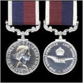
R.A.A.F. Long Service Medal
Awarded to Alan Bowers (A236814) who was a R.A.A.F. dental mechanic who serverd during WWII including service in Darwin, and then continued in the R.A.A.F. for some years after the end of WWII The Royal Australian Air Force (and all Commonwealth Air Forces) Long Service and Good Conduct Medal: Awarded to NCOs and ORs of the RAAF (RAF, RCAF etc) for 15 years service. A cupro-nickel plated medal, the obverse features the sovereign's head, the reverse features the crown and eagle emblem of the RAAF (and RAF). Officers are eligible for the award provided they have served a minimum 12 years in the ranks. The riband is dark blue and maroon with white edges. This medal ceased to be awarded in Australia in 1975 when it was replaced by the National Medal (and sbsequently the DFSM and DLSM) in the Australian system of honours and awards. http://www.heritagemedals.com.au/medals-1/service-long-service/air-force-long-service-and-good-conduct-medal.html History of the RAAF Dental Branch It took six years following the formation of the RAAF in 1921 for the first Dental Clinic to be established at Point Cook, Victoria. On 10th June 1927 Flying Officer James Carl Rosenbrock commenced work as an RAAF Dental Officer for the FlyingTraining School at Point Cook. As personnel numbers were still relatively small, Rosenbrock was also responsible for the dental care of all Victorian RAAF units, which involved treating members at 1AD Laverton, as well as Air Force Headquarters at Victoria Barracks in Melbourne. As Army Dental Officers were currently caring for RAAF personnel at Richmond, NSW, the Senior Dental Officer of the 3rd Military District in Victoria (SDO 3MD) requested through the military board that a similar arrangement be established, where that the newly appointed RAAF Dentist provide part time dental services to the Army units stationed at Queenscliff. This was seen as an effective reciprocal arrangement, with both units having a Dental Officer in attendance for, in total, around 3-4 weeks a year. Rosenbrock continued to serve as the sole RAAF Dental Officer until the middle of 1933, when the Air Board asked for his service to be terminated following ‘behaviour unbecoming of a RAAF officer'. He had borrowed several sums of money, of around 40 Pounds or so, from junior ranks on base (as well as from the Regimental Sergeant Major) and had failed to pay the money back. He was replaced by a fellow Victorian, FLGOFF Norman Henry Andrews, on the 18th Sep 1933, who went on to become our first Director of Dental Services, and was instrumental in establishing the organisations and conditions of the Branch that are still present today. Through a fair amount of persistence and hard work on the part of Norman Andrews, the RAAF Dental Branch began to expand from 1937, with the introduction of 2 additional positions, at RAAF station Richmond, and at the FlyingTraining School at Point Cook. This gave the RAAF 3 uniformed Dental Officers, which was expanded to 5 in the months leading up to WW2. 4 of these Dental Officers were based in Victoria and 1 at Richmond, with the other two RAAF units being cared for by the Army (as in the case of Pearce in WA) or by civilians (as in Darwin). With the sudden increase in RAAF personnel required at the outbreak of WW2, the number of RAAF Dental Officers increased dramatically, from 5 in 1939, 28 in 1940, 64 in 1941, 147 in 1942, 193 in 1943, 219 in 1944, and peaking at 227 in 1945. RAAF Dental Officers were required to work in a variety of locations, both in and out of Australia. Between 1940 and 1942 a massive construction programme occurred, with new dental clinics being established around Australia. Priority was given to aircrew training units in order to get these personnel dentally fit for operational deployment, but Dental Officers could equally find themselves posted to recruit depots, fixed stations, medical clearance stations, mobile dental sections, and RAAF and civilian hospitals. RAAF Dental Officers were posted to the large dental centres at Ascot Vale (Vic) and Bradfield Park (NSW) when first appointed, where they received military and clinical training, before being deployed to their needed location. Mobile Dental Units When Japan entered the war in 1941, the rapid deployment of troops to northern operational areas with less than ideal dental fitness was extremely high. As a result, the RAAF deployed a range of mobile dental units, either alone or with medical sections, to support the increasing number of isolated deployed personnel within Australia and overseas. There were three types of mobile unit used: a. Mobile Dental Unit – relied on using either a semi-trailer to get around or by building a surgery directly on to the truck chassis, and installing hydraulic chairs, units, x-rays, and laboratory equipment. They were able to move around between small units, such as RAAF radar stations, where they could plug into the local power supply and work immediately. b. Transportable Dental Units – used for stops of longer duration, where field equipment was carried in panniers from one unit to another by road or rail and housed in whatever accommodation was available at the destination. They were often carried within Australia on Tiger Moths and Dakota aircraft. c. Itinerant Dental Units – in some areas, the dental equipment was installed at the RAAF unit and the Dental Officer and their staff would travel from unit to unit, using the equipment available at each location. RAAF Dental BadgeAs the war developed in Europe, it soon became obvious that the RAF Dental support was not capable of supporting the increasing numbers of RAAF aircrew that were being sent for service with the RAF, with only enough Dental Officers available to provide one to every 2000 men ( instead of the preferred 1 to 600). As a result, the RAAF provided a mobile dental unit, fitted out in a caravan and pulled by a Ford V8 Coupe, to travel around England in support of RAAF personnel at various squadrons. Some degree of tact was needed to ensure that the RAF did not take this as a comment on the treatment they were providing, but it proved successful in maintaining a satisfactory state of dental fitness in RAAF personnel, and a second mobile unit was soon dispatched. They were also set up with a laboratory on board as well as the surgery, which was a major difference between the RAF and RAAF, as the RAF did not provide dentures for their troops (the RAAF would, providing they had served for 6 years). In 1943 the RAF was no longer able to provide Dental support to Australian troops in the Middle East, which resulted in the need for a transportable dental unit to be deployed from Australia. It functioned in a similar manner to the RAF, by moving from one squadron to another. It served in the Middle East and Africa, from Cairo across North Africa, to Italy, and eventually back to England to treat returned prisoners of war. GPCAPT Norman Andrews The growth and development of the RAAF Dental Branch owes a debt to one man in particular, GPCAPT Norman Andrews. As the second RAAF Dental Officer to enlist on 18 Sep 1933, Andrews became the principal architect of the structure and organisation of the RAAF Dental Branch leading up to and during WW2. Until early 1940, the RAAF Dental Branch was administered by the Director of Medical Services (Air), which placed it under the control of the Army Medical staff. The Army would provide their Inspector of Dental Services for advice whenever needed. In April 1940, the RAAF Medical service separated from the Army, resulting in the control of the RAAF Dental Branch shifting back to the RAAF. Andrews became the first Director of Dental Services, when the position was created in 1943 as recognition of the higher profile the Dental Branch was now playing in the RAAF Medical service. Until this time, Andrews's title had been as the Dental Staff Officer to the RAAF Medical Service. Andrews was responsible for the establishment of the war-time structure of the Dental service, establishing new dental centres at all major bases, creating mobile and transportable dental units, ensuring the continual growth of the Branch, maintaining professional development of staff through the establishment of a professional journal, and by organising renowned lecturers to speak at RAAF bases. He also believed in visiting as many dental units as possible to see for himself what conditions were like and to talk first-hand to staff in remote units. His itinerary during the war years, both in and out of Australia, shows a large number of trips in a variety of modes of transport in order to reach remote areas where units were serving. He was promoted to GPCAPT in July 1944, as the numbers of Dental Officers soon peaked at 227 towards the end of the war (1 GPCAPT, 9 WGCDRs, 60 SQNLDRs, and 157 FLTLTs). After the war, with the reduction in RAAF personnel required in uniform, the Dental Branch also reduced its numbers significantly. By 1947 there were only 18 Dental Officers serving (many part-time), with 1 GPCAPT, 1 WGCDR, 10 SQNLDRs, and 6 FLTLTs, and only 13 by 1950. With the decrease in Branch personnel numbers, the ‘powers to be' saw fit to reduce the Director of Dental Service rank to WGCDR, and as a result Norman Andrews found that in order to continue serving in the RAAF he would have to wear a reduced rank. This appears to have been a contributing factor in his decision to discharge at the relatively early age of 43 and accept an administrative job as Director of the Victorian Government's School Dental Service. Norman Andrews holds the proud honour of being the founder of the RAAF Dental Branch, which during the war was instrumental in educating servicemen of the importance of dental health and maintaining the dental fitness of troops in a variety of areas. Dental Orderlies (Assistants) The dental orderly mustering was first introduced in 1937. Until that time, medical orderlies were assigned to assist the Dental officer with their duties. As early as 1931 it had been noted by both RAAF and Army Dental Officers working in Victoria and Richmond that a lot of the troubles they were having would be solved by appointing a permanent Dental Orderly. Often they would find that the medical orderly they were assigned was a different one each day, and as a result the administration and work in general was very inefficient. By 1937, with the increase in Dental Officers to 3, it was realised that a Dental Orderly mustering needed to be created. Dental Mechanics/Technicians Before WW2, dental laboratory work was provided by civilian laboratories, as most RAAF units were stationed around metropolitan areas. At this time, service personnel were still required to pay for their own dentures, unless they had served for six years or had their dentures damaged during performance of their duties. In July 1940, mainly in response to the development of more remote RAAF dental units and the increasing demand for dental prostheses, the Dental Mechanic mustering was established. Unfortunately there was a very limited pool of civilian dental mechanics to recruit from, and as a result the RAAF set up a training school at Laverton (which was later moved to Ascot Vale) in June 1941 which conducted an intensive 6 month course in Dental mechanics. Dental mechanics were quickly in demand. In all fixed and mobile dental units at least 1 Mechanic was supplied for each Dental Officer, and indeed the RAAF supplied Dental Mechanics throughout all its deployments, something the RAF were unwilling, or unable, to do. Two grades of dental mechanic existed: the Senior Mechanic (with the rank of NCO), who was competent in all phases of laboratory work; and the Junior Mechanic, who could only handle routine work and not more advanced denture work. The progression to Senior required a further trade test in techniques including setting up, clasp-forming, casting and backing teeth. During the course of the War, two special courses were held for Mechanics. The first, directed at senior mechanics so that they could instruct others, was in 1942 when Acrylic Resin was first introduced as a denture base material, as an alternative to the current option of vulcanite. Later, towards the end of the War, a ‘refresher' course was provided for those that had served for the greatest period of time in order to allow them retraining in techniques that they had not practised during their service and which were common in civilian life. This included cast base dentures, crowns and bridges, partial dentures, and retainers. Towards the end of the War, a course was held with WAAAF trainees to train them as Mechanics. However, as the War was soon to end they never had the opportunity to progress within the mustering to become Senior Mechanics. The RAAF Dental Branch has survived 75 years of turbulence, with reviews of its viability occurring regularly every few years from as early as 1937. The Branch continues to provide excellent service to the ADF community and, despite reduced manpower, will continue to play an important role in Air Force Health operations. http://www.defence.gov.au/health/about/docs/RAAFDental.pdf40cm cupro-nickel plated medal, the obverse features the sovereign's head, the reverse features the crown and eagle emblem of the RAAF (and RAF). A23814 BOWERS.A. A. F.r.a.a.f long service medal, r.a.a.f good conduct, r.a.a.f. dental service medal -
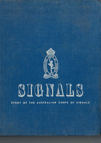 Lara RSL Sub Branch
Book, Signals - Story of the Australian Corps of Signals, 1953
Little has been written previously about this technical group of men and women and that their duties were under insurmountable difficulties which they faced and overcome in conditions that were encountered in the desert and jungle warfare. Without their constant and never ending services, the task of the force in bringing to a close this fight for freedom would have been greatly handicapped.An outline of the Australian Signals Corps over the years from the campaign in the Middle East to the present day of the victories in New Guinea. A tribute to the corps that stayed on duty every hour of every day providing and maintaining vital communication channels.Signals - Story of the Australian Corps of Signals. Green front and back hardcover with black text and insignia. Photographs, cartoons, illustrations and poems. The inside front and back covers have a photograph montage in green sepia.signal corps, wwii, c.h.simpson, motorcycle couriers, signals 7 australian division, lt.commander b.t.r chadd, palestine, spark plug, semiphore, morse code, field radio, a.i.f, british signals corps, pieter mersk, breconshire corp signals, new guinea, malaysa, singapore, switchboard, carrier pigeons, linesmen, gaza signal office -
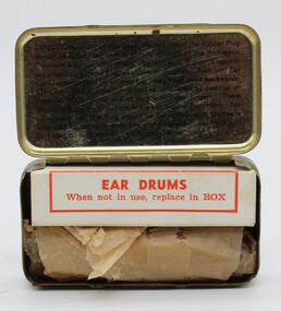 Shepparton RSL Sub Branch
Protectors ear drum, ear protectors
standard for all services in the 1950's and 1960's mass produced moulded tin.ear protection as issued to all personalKhaki painted tin, hinged lid written instructions in lid, diagrammatic instructions in base in black lettering.Protectors ear drum (aust.) MK1 M Large on outside of lid. For inscription of internal markings refer to photo's of inside of tin.ear plugs, ear protectors -
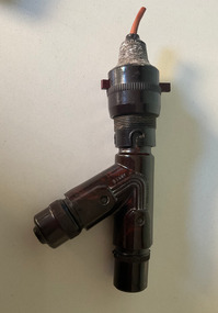 City of Moorabbin Historical Society (Operating the Box Cottage Museum)
Functional object - Lamp fitting double holders, Middy's Aust, c 1930
Made in Australia by Middy's Used by a pioneer family in Moorabbin. Manufactured by Middy's: Arriving in Australia at age 19 by ship at Port Melbourne, Dutch immigrant Petrus Cornelis Nicolaas Middendorp (1891-1963) settled in Melbourne to apply his trade as a cigar maker for the British American Tobacco Co. Retiring from the cigar industry and following his work as an honorary orderly tending WW1 Australian casualties in Paris and Melbourne, Petrus began selling Dutch manufactured light globes, vacuum cleaners and other electrical products imported from Holland and England. Warehousing and sales of the goods were undertaken from 1928 by the ‘Middendorp Goods Supply Company’ initially located in Flinders Lane in Melbourne’s CBD, then moving to McKillop Street, followed by a basement store at 148 Queen Street. During the 1940s a manufacturing plant known as ‘Middendorp and Sons’ was established in the Melbourne suburb of Preston, where Petrus’ three teenage sons Peter, Nick and Hugh joined him. Peter and Hugh worked with a small team of staff to produce rubber plug tops, extension sockets, double adaptors and a small range of bakelite accessories, whilst Nick became the first sales rep calling on customers and construction sites. The products were sold under the brand name of ‘Middy’. A name change of the distribution business took place in the late 40s and Middendorp Electric Company Pty Ltd was officially registered in 1948. The manufacturing operation ceased during the late 50s due to the introduction and acceptance of plastic and injection moulding. However, the Middendorp family had positioned itself to further establish its electrical wholesale business with the first branch and Head Office opening in 1956, located at 520 Latrobe Street, Melbourne. By 1962 there were five trading branches, growing to 25 in 1986 and 101 by 2018 Australia wide. Middendorp Electric, more commonly known as Middy’s and readily identified by its trademark colour of Middy’s pink, has developed into the largest privately owned Electrical Wholesaler in Australia. In 2015 Middy’s acquired Mekolec lifts fire and electrical adding presence and sector expertise in Melbourne’s inner south. In Sep 2018 Middy's acquired Salmon Brothers Electrical, with 5 Branches in Sydney's Metro region and in 2019 they acquired Goulburn Electrical Wholesalers greatly adding to Middy's location coverage in NSW and providing Middy’s the ability to better service NSW contractors. Bakerlite electrical fittingMiddy - Made in Australiamiddy's, moorabbin pioneers, electrical, bakerlite -
Coal Creek Community Park & Museum
Tobacco plug
Rectangular shaped pouch of tobacco, cream coloured with red text and gold decoration. Harbour Bar, Special Virginia tobacco. Ready Rubbed, fine cut -
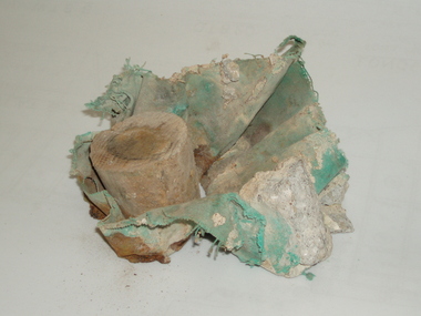 Bay Steamers Maritime Museum
Functional object - Wooden bung, Wooden bung found plugging a hole in the hull of Wattle, c.1971
Wooden bung removed from the steam tug wattle. Found in the bilges of the vessel in the concrete ballast.At an unknown time the bung was used to plug a leak in the hull and concreted over. Uncovered during restoration of forward starboard section of the hull.Circular wooden bung enclosed in a small section of green canvas with fragments of concrete attachedwattle, wooden bung, canvas, restoration -
Moorabbin Air Museum
Manual (Item) - Application Data - Spark Plug Leads
Description: 100 pages. Published by Piper Aircraft Corp. Published 3/5/1972. Piper PA.31:350 Aircraft Flight Manual Level of Importance: World. -
Moorabbin Air Museum
Manual (Item) - Champion Aviation Spark Plugs Service Manual
Description: 9 pages. Published by Bendix Automotive Service Division (Corporation). Published August 1963. Bendix Fuel Pump Service Manuals Level of Importance: World. -
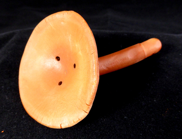 Ballarat Base Hospital Trained Nurses League
Gastrostomy Plug
English catheter size - brown rubber.gastrostomy plug -
Whitehorse Historical Society Inc.
Article, Leak plugged in time, 2010
Article on a leak of harmful coolant from Gainsborough Hardware Industries into a stormwater drain and the Environment Protection Authority's order to the company to remedy the problem.Article on a leak of harmful coolant from Gainsborough Hardware Industries into a stormwater drain and the Environment Protection Authority's order to the company to remedy the problem.Article on a leak of harmful coolant from Gainsborough Hardware Industries into a stormwater drain and the Environment Protection Authority's order to the company to remedy the problem.gainsborough hardware industries ltd, blackburn creek -
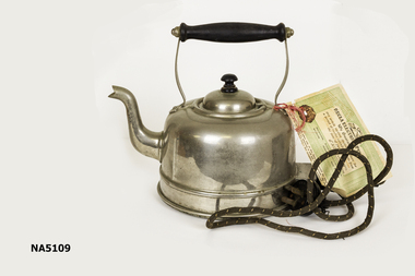 Whitehorse Historical Society Inc.
Domestic object - Electric kettle with plug-in cord, Heda Kettle, Unknown
Chrome 'Heda' electric kettle with spouted lid, also wooden handle. Had cardboard guarantee card attached.ON base - 'solid copper' plate Heda kettle Made in Australia Volts 230 Amps Patent No. 19084 manufactured by C. W. Marriott Melbournekettle, electric kettle, heda -
Moorabbin Air Museum
Manual (Item) - BG Spark Plugs Service And Maintenance Manual, BG Spark Plugs Shielded And Unshielded Service And Maintenance Manual
The BG Corporation -
Moorabbin Air Museum
Manual (Item) - Lodge Plugs Ltd - Jet Engine Igniters Recommendations and servicing instructions
-
Moorabbin Air Museum
Plan - Drawings: 88732 (Proposed D/F Aerial, D/F Aerial Proposed Layouts, Aerials Arrangement, Aircraft Sealing, Cabinet Layout, Proposed Mounting, Proposed ‘Porters Installation), 89685 - Aerial Column Assembly, 89686 - Aerial Assembly, 89688 - Housing Top, 89689 - Housing Bottom, 89690 - Housing, 89691 - Screen, 89696 - Assembly Aerial Flange, 89699 - Flange, 8o702 - Stub Shaft, 89703 - Tube Inner, 89704 - Housing, 89705 - Bearing Upper, 89706 - Block Lamps, 89707 - Bracket, 89708 - Body, 89709 - Plate Illuminating, 89710 - Stop Plate, 89711 - Block Plug Mount, 89712 - Cap, 89713 - Scale, 89714 - Spacer, 89715 - Catch Pin, 89780 - Aerial Assembly, 89791 - Top Steady Anchorage Assembly, 90072 - Modifications Cessna, 90376 - Aerial Assembly Porter, 90391 - Modifications Porter, 90405 - Drilling Jig, o3031 - Experimental Auxiliary Aerial Project Thorough, Weapons Research Establishment
-
Moorabbin Air Museum
Drawing (Item) - approx 50 drawings some duplicated including bomb carriers cockpit instruments towing gear gipsy engine propeller airscrew liberty engine plug connectors gun sight tail wheel gun synchronising windscreen, Westland Wapiti blueprint drawings
-
Moorabbin Air Museum
Manual (Item) - Champion Aviation Spark Plugs Service Manual, Champion Aviation Spark Plugs Aviation Service Manual
Champion Aviation Products -
Moorabbin Air Museum
Drawing - Drawing Nos. 89692 - Gasket; 89693 - Plug Modified; 89694 - Element Outline; 89695 - Spacer; 89697 - Nut; 89698 - Washer; 89700 - Post; 89701 - Key; 89716 - Pin Threaded; 89717 - Connector Bracket; 89718 - Sliding Lock Retainer; 89719 - Block; 89720 - Straight Clamp; 89721 - Socket Modified; 89722 - Plate Mounting; 89723 - Plate Receptacle Mount; 89724 - Spring; 89u25 - Spring; 89726 - Spring; 89727 - Spring; 89728 - Bracket; 89729 - Clamp; 89730 - Pin Stop; 89731 - Button; 8o732 - Pin; 89733 - Nut; 89734 - Spring; 89735 - Cover Hinged; 89736 - Plate Hinge; 89737 - Washer; 89738 - Washer; 89739 - Washer; 89740 - Clamp Top; 89741 - Clamp Bottom; 89742 - Screw; 89743 - Mount; 89744 - Brake Sub Assembly; 89745 - Screw; 89746 - Sliding Lock Post; 89747 - Shaft; 89748 - Flange; 89749 - Brake; 89750 - Tappet; 89751 - Screw Top Plate; 89752 - Ring Retaining; 89753 - Locking Ring; 89754 - Knob; 89755 - Bearing Lower; 89756 - Plate; 89757 - Pin; 89758 - Hand Grip; 89759 - Pin Cam; 89760 - Insert; 80761 - Spacer; 89762 - Seal; 89763 - Bar Handle; 89764 - Key; 89765 - Ring Rotating; 89766 - Screw; 89767 - Support Ring; 89768 - Circlip; 89769 - Switch, Weapons Research Establishment