Showing 19 items matching "air resistance"
-
 Moorabbin Air Museum
Book - Aerodynamics, The Science of Flight
... ...Air resistance...Moorabbin Air Museum Moorabbin Airport 12 First Street Moorabbin melbourne Aerodynamics Aerodyamic beginnings Air resistance Wing theory Flight stability High speed flight Overview of aerodynamics circa 1949 The Science of Flight Book Aerodynamics ...Overview of aerodynamics circa 1949non-fictionOverview of aerodynamics circa 1949aerodyamic beginnings, air resistance, wing theory, flight stability, high speed flight -
Moorabbin Air Museum
Book - Aircraft construction, An Elementary Course in the Construction of Aircraft
... ...Air resistance...Aircraft construction The atmosphere Air resistance Aerofoils The flight of the airplane Stability & control The airscrew Overview of the theories underlying practical aeronautical engineering, circa 1940 An Elementary Course in the Construction of Aircraft Book Aircraft construction ...Overview of the theories underlying practical aeronautical engineering, circa 1940non-fictionOverview of the theories underlying practical aeronautical engineering, circa 1940the atmosphere, air resistance, aerofoils, the flight of the airplane, stability & control, the airscrew -
Frankston RSL Sub Branch
Drift Recorder, W & G, A M Drift Recorder MKII, 1930 - 1939
... Thus, in order to score a hit, the bomber had to fly a ground track that ran upwind of the target." "Air resistance acting on a bomb after release caused it to lag behind the drop point and hit somewhere behind the bomber. ...Thus, in order to score a hit, the bomber had to fly a ground track that ran upwind of the target." "Air resistance acting on a bomb after release caused it to lag behind the drop point and hit somewhere behind the bomber. ...Purpose built mechanical calculation machine for determining the drift of aircraft when operating in crosswind conditions. This device has an eyepiece and a prismatic periscope for viewing a distant feature being tracked. This device has calibrated rotary scales for height, speed (in KNOTS and MPH), and an adjustment to preset the 'crab angle' of the aircaft for cross wind compensation. The device can be opened for cleaning or maintenance purposes. Refer to the following extracts for information about bomb drift: "Crosswinds brought into the bombing problem a new factor, "drift" In order to fly a given ground track in a crosswind, an aircraft had to "crab" into the wind; the angle formed between the aircraft's true heading and its ground track was called the "drift angle" In a crosswind, the bomb would impact directly behind the aircraft and along its longitudinal axis at the moment of release. But this meant that the bomb would strike the ground at some point downwind of the aircraft's ground track. Thus, in order to score a hit, the bomber had to fly a ground track that ran upwind of the target." "Air resistance acting on a bomb after release caused it to lag behind the drop point and hit somewhere behind the bomber. The distance from a point beneath the aircraft at the instant of bomb impact to the point of bomb impact was called "trail." Trail increased as the bomber's airspeed increased or as its altitude increased. Furthermore, since different bombs encountered different resistance in the air, trail was also a factor of bomb shape."A. M. Drift Recorder MKII REF. No 6B/190 No 2668/41 X/ 3606 3E4H28 -
 Ballarat Tramway Museum
Document - Instruction Book, Westinghouse Brake Company of Australasia Limited and The Westinghouse Brake & Saxby Signal Co. Ltd. of 82 York Road and Kings Cross London, "Westinghouse Railway Operating Data", 2000
... Contains data sheets regarding motors, commutators, brushes, armatures, bearings, field coils, pinions, lubrication, air piping, axle collars, resistance grids, gear cases and other technical information. ...Contains data sheets regarding motors, commutators, brushes, armatures, bearings, field coils, pinions, lubrication, air piping, axle collars, resistance grids, gear cases and other technical information. ...Photocopy of 54 data sheets published by Westinghouse Electric & Manufacturing Company of East Pittsburgh Pa, USA c1920. Consists of plastic cover, header page with Westinghouse logo, contents sheets (2 pages), forward, 67 pages (single side photocopy) and heavy rear card cover bound with a green comb binder. Original material lent by Craig Tooke of the Melbourne Tramcar Preservation Association at Haddon. Photocopied by Warren Doubleday March 2000. List of contents produced 30/6/2000 and then bound. Contains data sheets regarding motors, commutators, brushes, armatures, bearings, field coils, pinions, lubrication, air piping, axle collars, resistance grids, gear cases and other technical information. Westinghouse Railway Operating Data 30/6/2000 List of Contents Page No. Care and repair of commutators 1 Undercutting commutators 2 Railway Motor carbon brushes 3 Brush holders 4 Flashing of railway motors 5 Soldering railway armatures 6 Armature Winding 7 Banding armatures 8 Railway Motor Bearings 9 Lubrication of railway motor bearings 10 How to babbitt motor bearings 11 Oil, grease and waster for motors and gears 12 Saturation of motor bearing waste 13 Testing Polarity of Field Coils 14 Charging of storage batteries on Interurban & street rail cars 15 Precautions to be taken with blower installations on motor cars 16 Putting on Railway Motor Pinions 17 How to take armatures out of box frame motors 18 Dipping and Baking of Railway Motors 19 War time dipping and baking outfits 20 Dipping and baking railway motors will decrease troubles 21 Protection of Motor Bearings from Dust 25 Winter Operation of Railway Motor equipments 26 Installation of Air piping to prevent freezing 27 Maintenance of Traction Brake Equipment 28 Maintenance of controller fingers and contacts 29 Hand operated circuit breakers 30 Railway Motor Testing I 31 Railway Motor Testing II 33 Railway Motor Testing III 35 Railway Motor Testing IV 36 Railway Motor Testing V 37 Removing and replacing railway motor armature shaft 39 Mounting and Maintenance of car resistors 40 Lubrication of control apparatus 41 Maintenance of fuse boxes for railway service 42 Does it pay to dip and bake armatures 43 Dipping and Baking as a financial asset 44 Shop Organisation 45 Tinning Malleable Iron Bearing shells 46 Life of armature bearings or railway motors 47 The assembly of complete sets of commutator segments 48 Electric welding as a factor in reclamation 50 Metal to Metal press, shrink and clamping fit allowances 52 Life of railway motor carbon brushes 54 General information of grid resistance design for the operating man 56 Stopping a car by braking with the motors 57 Railway Motor shafts and their maintenance 58 Axle collars 59 Gear cases 60 Ventilated railway motors 62 Revamping Loose armature bearings 64 Life of axle bearings of railway motors 65 Heat-treated bolts for railway service 66 Document imaged over 7 parts 7-9-2016 - see hi res files. trams, tramways, westinghouse, motors, data sheets, technical information -
 Bendigo Military Museum
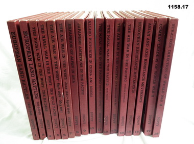
Book - BOOKS, Trevor Nevitt Dupuy, Col US Army Retired, The Military History of World War II (17 Volumes), c.WWII
... Red buckram hard covers, black & white photos & illustrations, black & white text on cover. .1) European Land Battles 1939-43, 91 pages .2) European Land Battles 1944-45, 83 pages .3) The Nard Wat in the West .4) The Nard War in the West - The Raiders, 67 pages .5) The Nard War in the West - The Wolf Packs, 60 pages .6) Air War in the West Sept 1939 - May 1941, 76 pages .7) Air War in the West June 1941 - April 1945, 66 pages .8) Expansion of Japan in Asia, 68 pages .9) Japanese Ambitions in the Pacific, 119 pages .10) Allied Victories in China / Burma, 66 pages .11) The Nard War in the Pacific - Rising Sun of Nippon, 90 pages .12) The Naval War n the Pacific, 89 pages .13) The Air War in the Pacific, 88 pages .14) The Air War in the Pacific - Victory in the Air, 89 pages .15) European Resistance Movements, 88 pages .16) Asian and Axis Resistamce Movements, 88 pages .17) Combat Headers of World War II, 126 pages .18) Strategic Directions of World War II, 65 pages...Bendigo Military Museum 37 - 39 Pall Mall Bendigo goldfields books history military Red buckram hard covers, black & white photos & illustrations, black & white text on cover. .1) European Land Battles 1939-43, 91 pages .2) European Land Battles 1944-45, 83 pages .3) The Nard Wat in the West .4) The Nard War in the West - The Raiders, 67 pages .5) The Nard War in the West - The Wolf Packs, 60 pages .6) Air War in the West Sept 1939 - May 1941, 76 pages .7) Air War in the West June 1941 - April 1945, 66 pages .8) Expansion of Japan in Asia, 68 pages .9) Japanese Ambitions in the Pacific, 119 pages .10) Allied Victories in China / Burma, 66 pages .11) The Nard War in the Pacific - Rising Sun of Nippon, 90 pages .12) The Naval War n the Pacific, 89 pages .13) The Air War in the Pacific, 88 pages .14) The Air War in the Pacific - Victory in the Air, 89 pages .15) European Resistance Movements, 88 pages .16) Asian and Axis Resistamce Movements, 88 pages .17) Combat Headers of World War II, 126 pages .18) Strategic Directions of World War II, 65 pages The Military History of World War II (17 Volumes) Book BOOKS Trevor Nevitt Dupuy, Col US Army Retired Franklins Watts Inc ...Red buckram hard covers, black & white photos & illustrations, black & white text on cover. .1) European Land Battles 1939-43, 91 pages .2) European Land Battles 1944-45, 83 pages .3) The Nard Wat in the West .4) The Nard War in the West - The Raiders, 67 pages .5) The Nard War in the West - The Wolf Packs, 60 pages .6) Air War in the West Sept 1939 - May 1941, 76 pages .7) Air War in the West June 1941 - April 1945, 66 pages .8) Expansion of Japan in Asia, 68 pages .9) Japanese Ambitions in the Pacific, 119 pages .10) Allied Victories in China / Burma, 66 pages .11) The Nard War in the Pacific - Rising Sun of Nippon, 90 pages .12) The Naval War n the Pacific, 89 pages .13) The Air War in the Pacific, 88 pages .14) The Air War in the Pacific - Victory in the Air, 89 pages .15) European Resistance Movements, 88 pages .16) Asian and Axis Resistamce Movements, 88 pages .17) Combat Headers of World War II, 126 pages .18) Strategic Directions of World War II, 65 pagesbooks, history, military -
 Monbulk RSL Sub Branch
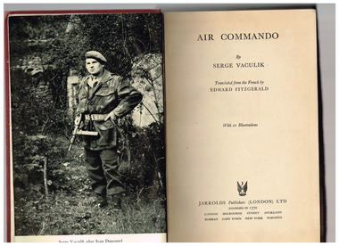
Book, Serge Vaculik, Air commando, 1954
... Monbulk RSL Sub Branch 48 Main Road Monbulk yarra-valley-and-the-dandenong-ranges World war 1939-1945 - Personal narratives - France World War 1939-1945 - Resistance movements Personal recollections of a French resistance fighter Ill, p.303. Air commando Book Serge Vaculik Jarrolds ...Personal recollections of a French resistance fighterIll, p.303.non-fictionPersonal recollections of a French resistance fighterworld war 1939-1945 - personal narratives - france, world war 1939-1945 - resistance movements -
 Flagstaff Hill Maritime Museum and Village
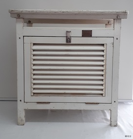
Equipment - Stevenson Screen, Thomas Stevenson, ca. 1910
... air to flow around them. Sometimes other meteorological instruments were included in the weather stations, so there were different Stevenson Screen sizes. This authentic, original Stevenson screen was previously owned by the Australian Bureau of Meteorology and was used for many years for weather readings at the Cape Otway Light Station in southwest Victoria. The Lighthouse Keepers recorded the readings for minimum and maximum temperatures at 9 a.m. every day from January 1865 until April 1994. The equipment was sheltered in a Stevenson Screen from 1902 until April 15 1994, when the mercury thermometer was replaced by a platinum resistance...air to flow around them. Sometimes other meteorological instruments were included in the weather stations, so there were different Stevenson Screen sizes. This authentic, original Stevenson screen was previously owned by the Australian Bureau of Meteorology and was used for many years for weather readings at the Cape Otway Light Station in southwest Victoria. The Lighthouse Keepers recorded the readings for minimum and maximum temperatures at 9 a.m. every day from January 1865 until April 1994. The equipment was sheltered in a Stevenson Screen from 1902 until April 15 1994, when the mercury thermometer was replaced by a platinum resistance ...Stevenson screens were first introduced in Australia in the 1880s and were widely installed by 1910. The screens have been used to shelter and protect thermometers and other meteorological instruments from rain and direct heat while the holes and double-louvre walls allowed air to flow around them. Sometimes other meteorological instruments were included in the weather stations, so there were different Stevenson Screen sizes. This authentic, original Stevenson screen was previously owned by the Australian Bureau of Meteorology and was used for many years for weather readings at the Cape Otway Light Station in southwest Victoria. The Lighthouse Keepers recorded the readings for minimum and maximum temperatures at 9 a.m. every day from January 1865 until April 1994. The equipment was sheltered in a Stevenson Screen from 1902 until April 15 1994, when the mercury thermometer was replaced by a platinum resistance probe within an Automatic Weather Station (AWS). This Stevenson screen is one of the two screens that then became redundant. The other Stevenson screen was kept to display to visitors. Lightkeepers were no longer required at the Cape Otway Light station either, due to the automated system. The meteorological instruments donated with the screen were used for measuring temperature and humidity. They are mounted on a metal bracket that fits across the screw holes on the screen’s internal frame. The glass-covered Relative Humidity (RH) sensor was made by the renowned precision instrument maker, Rotronic AG of Switzerland, which was founded in 1965. The firm made its first electronic temperature and humidity instrument in 1967. Meteorological records have been collected in Australia from the 1800s. The records were collated, published and used as a basis for weather forecasts. Many sectors, such as maritime and agriculture industries, have relied on these figures for making important decisions. The quality and placement of the meteorological instruments used to measure temperature and humidity are of utmost importance for accuracy. In early colonial times, there were no national standards for meteorological instruments that would allow for accurate figures and comparisons. Once the Bureau of Meteorology was established (around 1908 to 1910) the department installed Stevenson screens throughout Australia, many at lighthouses and light stations, and the measuring instruments were standardised. The Stevenson Screen was named after its inventor, Scottish Civil Engineer Thomas Stevenson (1818-1887) who was also the father of Robert Louis Stevenson, author. Stevenson developed the small thermometer screen around 1867. It had double-louvred walls around the sides and a top of two asbestos sheets with an air space between them and was thickly painted with a white coating that reflected the sun’s rays. This design was modified in 1884 by Edward Mawley of the Royal Meteorological Society. Standards were set for the locations of the screens and instruments, including their distance above ground level and the direction the door faced.Stevenson screens played a significant part in providing a standardised shelter for all meteorological instruments used by the Australian Bureau of Meteorology from about 1910 until 1994. The readings from the instruments gave the meteorological statistics on which weather forecasts throughout Australia were based. This Stevenson screen was used locally at Cape Otway, along the Great Ocean Road in southwest Victoria, so contributed towards our local forecasts and weather warnings.Stevenson screen, original, from the Australian Bureau of Meteorology’s weather station at the Cape Otway Lighthouse. The screen is a white wooden cupboard with a slanted cover raised above the top. The top has ten drilled ventilation holes, and the sides and door are made of downward-slanting double louvres. Two brass hinges join the door to the lower edge of the screen and a metal fitting at the top edge allows for a padlock closure. The screen is supported on four short legs, each with a hole drilled from side to side for fitting to a frame. Inside the screen are two wooden frames fitted with hooks and screws. The floor has three boards; one across the back and one across the front at the same level, and a board wider than the space between these boards is fitted higher, overlapping them slightly. Inside the screen, a pair of electronic instruments with short electric cables is mounted on a metal bracket with drilled holes in it. One of the instruments is a Relative Humidity (RH) probe. It is 26 cm long and is a glass tube with a filter on one end and an electrical connection on the other. It has inscriptions on its label, showing that was made by Rotronic AG, Switzerland. The other instrument is a Resistance Temperature Device (RTD) thermometer. It is 22.5 cm long and has a narrow metal probe joined to a hexagonal metal fitting. A brass plate on the front of the screen has impressed inscriptions. The screen is Serial Number 01/C0032, Catalogue Number 235862.Stamped into brass plate "CAT. NO. / 253862 / SERIAL NO. 01/C0032" On instrument’s electrical fitting; “CD2” [within oval ‘+’ above S] “Serie693 op65 / 220/380V~16A” On instrument’s glass; “rotronic ag” “SWISS MADE” “CE / CH-8303 / Bassersdorf” Symbol for [BARCODE] “ART NO MP 101A_T4-W4W” “POWER 4.8.30VDC“ “OP. RANGE: 0-100%RH/-40+60° C” “OUT H 0-100% 0-1V” “OUT T -40+60°C -0.4..+0.6V” “SERIE NO 19522 009”flagstaff hill maritime museum and village, warrnambool, maritime museum, maritime village, great ocean road, shipwreck coast, cotton region shelter, instrument shelter, thermometer shelter, thermoscreen, thermometer screen, measuring instruments, meteorological instrument, weather recording, weather station, lighthouse equipment, light station equipment, stevenson screen, marine instruments, mercury thermometer, platinum resistance probe, aws, automatic weather station, rotronic ag, swiss made, meteorological device, weather forecast, weather prediction, weather records, meteorological forecast, meteorological record, australian bureau of meteorology, bureau of meteorology, bureau, bom, relative humidity, rh, relative humidity probe, resistance temperature device, rtd, thermometer, temperature, humidity, cape otway, cape otway lighthouse, cape otway light station, rotronic, switzerland, swiss instrument, thomas stevenson, double-louvered walls, edward mawley, royal meteorological society, 01/c0032, serial number, cat. no. 235862, serial no. 01/c00323 -
 Flagstaff Hill Maritime Museum and Village
Plan - Ship Plan, Orient Steam Navigation Company, Orient Line, RMS Orion, ca. 1934
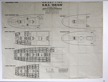
... air ventilation in buildings, ships and railroads. The system originated from Thermotank in Glasgow, Scotland. The ship plan for the RMS Orion is significant for its connection with the vessel. The ship was a leader, with several 'firsts'; the first Orient Line ship to be built with a single funnel since 1902, and the first to be painted in the Orient Line's livery, with a corn-coloured hull. It was the first liner to use chromium and bakelite materials for the surfaces throughout the ship, which provided greater resistance ...The Orient Steam Navigation Company Limited launched the Ocean Liner RMS Orion in 1934 and it remained in operation until 1963. The twin screw steamship was built to carry first class and tourist class passengers, over 1100 in all, plus almost 500 crew from Europe to Australia in comfort. The ship had a single funnel and a single mast. During WWII the vessel served as a troop carrier. The ventilation system noted on the plan, Punkah Louvre System, was designed for heating fresh air ventilation in buildings, ships and railroads. The system originated from Thermotank in Glasgow, Scotland. The ship plan for the RMS Orion is significant for its connection with the vessel. The ship was a leader, with several 'firsts'; the first Orient Line ship to be built with a single funnel since 1902, and the first to be painted in the Orient Line's livery, with a corn-coloured hull. It was the first liner to use chromium and bakelite materials for the surfaces throughout the ship, which provided greater resistance to the sea. It was also the first British ship to be fitted with air conditioning.Plan: printed provisional line drawing of the Orient line vessel "R.M.S. Orion". Inscriptions are printed on the plan. There are diagrams of six decks included in the plan. The ship is built for tourist "B" accommodation. The plan's Notices include details of the cabins including wardrobes, drawers, hinged seats, mattresses and bunk numbers. It also notes that there is a Punkah-Louvre System of Ventilation.Printed on the plan: "PROVISIONAL PLAN" "LOWER PROMENADE DECK" "UPPER CABIN DECK" "MAIN CABIN DECK" "LOWER CABIN DECK" "SUN DECK" "PROMENADE DECK" "ORIENT LINE / R.M.S. "ORION" / 24,000 TONS / TOURIST "B" CLASS ACCOMMODATION" "Owners: Orient Steam Navigation Company Limited"' "Managers : ANDERSON, GREEN & CO. LTD" "7 BISHOPS GATE, LONDON, E.C.2" "Chief Passenger Office : 14 Cockspur Street, London, S.W.1" "Branch Passenger Office : 1 Australia House, Strand, W.C.2" "notices"flagstaff hill, flagstaff hill maritime museum and village, warrnambool, maritime museum, maritime village, great ocean road, shipwreck coast, rms orion, plan, ship plan, provisional plan, orient line, orient ship, vissel orion, class b passenger accommodation, punkah louvre system of ventilation, deck plan, ship ventilation, ship floor plan, orient steam navigation company limited, anderson green & co ltd, steamship, ocean liner, war ship, troop carrier -
 Ballarat Tramway Museum
Book, Australian Commonwealth Engineering Standards Association, "Electrical Voltages and electrical frequencies for new installations", "Overhead Line wire material for telegraph and telephone purposes", "Telephone cable, paper insulated lead covered", "Dimensions and Resistances of Bare Annealed Copper Wire for Electrical Machinery and Apparatus", "Slate Slabs for Electrical Purposes", "Moulded Flat Top Insulation Bushes", "Insulation dimensions and resistance of enamelled plain copper wire for instruments and apparatus", "Watertight Glands for electric cables", "Air-break knife switches and laminated brush switches for voltages not exceeding 660Volts", 1926-1930
... "Electrical Voltages and electrical frequencies for new installations", "Overhead Line wire material for telegraph and telephone purposes", "Telephone cable, paper insulated lead covered", "Dimensions and Resistances of Bare Annealed Copper Wire for Electrical Machinery and Apparatus", "Slate Slabs for Electrical Purposes", "Moulded Flat Top Insulation Bushes", "Insulation dimensions and resistance of enamelled plain copper wire for instruments and apparatus", "Watertight Glands for electric cables", "Air-break knife switches and laminated brush switches for voltages not exceeding 660Volts"....1 - Book - 8 pages + grey covers, side stapled, issued by the Australian Standards Association, "Electrical Voltages and electrical frequencies for new installations ", C1 (a&b) - 1926, December 1926. .2 - Book - 36 pages + grey covers, side stapled, issued by the Australian Commonwealth Engineering Standards Association, Tentative Australian Standard - "Overhead Line wire material for telegraph and telephone purposes", C3-11-1925, November 1925. .3 - Book - 20 pages + brown covers, side stapled, issued by the Australian Commonwealth Engineering Standards Association, Tentative Australian Standard - "Telephone cable, paper insulated lead covered", C12 - 1928, January 1928. .4 - Book - 24 pages + grey covers, side stapled, issued by the Australian Commonwealth Engineering Standards Association, Tentative Australian Standard - "Marking for Switchboard bus-bars and connections" C13 - 1925, December 1925 - with a pasted green label noting that the "tentative standard is now endorsed as Australian Standard without amendment" - dated Oct. 1930. .5 - Book - 32 pages + grey covers, side stapled, issued by the Australian Standards Association, Tentative Australian Standard "Dimensions and Resistances of Bare Annealed Copper Wire for Electrical Machinery and Apparatus", C 18-1926, October 1926. .6 - Book - 12 pages + grey covers, side stapled, issued by the Australian Commonwealth Engineering Standards Association, Tentative Australian Standard "Slate Slabs for Electrical Purposes", C19 - 1926, July 1926. .7 - Book - 16 pages + grey covers, side stapled, issued by the Australian Commonwealth Engineering Standards Association, Tentative Australian Standard - "Moulded Flat Top Insulation Bushes" C20-1926, October 1926. .8 - Book - 16 pages + brown covers, side stapled, issued by the Australian Commonwealth Engineering Standards Association, Australian Standard "Insulation dimensions and resistance of enamelled plain copper wire for instruments and apparatus" C21-1928, January 1928. .9 Book - 20 pages + grey covers, side stapled, issued by the Australian Commonwealth Engineering Standards Association, Tentative Australian Standard - "Watertight Glands for electric cables" C22-1926, September 1926. .10 - Book - 20 pages + grey covers, side stapled, issued by the Australian Commonwealth Engineering Standards Association, Tentative Australian Standard - "Air-break knife switches and laminated brush switches for voltages not exceeding 660Volts" - C23 - 1926, August 1926" ...Ballarat Tramway Museum South Gardens Reserve Wendouree Parade Ballarat Ballarat goldfields Trams tramways Power Station Standards Materials Electrical Systems On top right hand corner has the date stamp of the "The Electric Supply Co. of Victoria Ltd Ballarat" .1 - Book - 8 pages + grey covers, side stapled, issued by the Australian Standards Association, "Electrical Voltages and electrical frequencies for new installations ", C1 (a&b) - 1926, December 1926. .2 - Book - 36 pages + grey covers, side stapled, issued by the Australian Commonwealth Engineering Standards Association, Tentative Australian Standard - "Overhead Line wire material for telegraph and telephone purposes", C3-11-1925, November 1925. .3 - Book - 20 pages + brown covers, side stapled, issued by the Australian Commonwealth Engineering Standards Association, Tentative Australian Standard - "Telephone cable, paper insulated lead covered", C12 - 1928, January 1928. .4 - Book - 24 pages + grey covers, side stapled, issued by the Australian Commonwealth Engineering Standards Association, Tentative Australian Standard - "Marking for Switchboard bus-bars and connections" C13 - 1925, December 1925 - with a pasted green label noting that the "tentative standard is now endorsed as Australian Standard without amendment" - dated Oct. 1930. .5 - Book - 32 pages + grey covers, side stapled, issued by the Australian Standards Association, Tentative Australian Standard "Dimensions and Resistances of Bare Annealed Copper Wire for Electrical Machinery and Apparatus", C 18-1926, October 1926. .6 - Book - 12 pages + grey covers, side stapled, issued by the Australian Commonwealth Engineering Standards Association, Tentative Australian Standard "Slate Slabs for Electrical Purposes", C19 - 1926, July 1926. .7 - Book - 16 pages + grey covers, side stapled, issued by the Australian Commonwealth Engineering Standards Association, Tentative Australian Standard - "Moulded Flat Top Insulation Bushes" C20-1926, October 1926. .8 - Book - 16 pages + brown covers, side stapled, issued by the Australian Commonwealth Engineering Standards Association, Australian Standard "Insulation dimensions and resistance of enamelled plain copper wire for instruments and apparatus" C21-1928, January 1928. .9 Book - 20 pages + grey covers, side stapled, issued by the Australian Commonwealth Engineering Standards Association, Tentative Australian Standard - "Watertight Glands for electric cables" C22-1926, September 1926. .10 - Book - 20 pages + grey covers, side stapled, issued by the Australian Commonwealth Engineering Standards Association, Tentative Australian Standard - "Air-break knife switches and laminated brush switches for voltages not exceeding 660Volts" - C23 - 1926, August 1926" "Electrical Voltages and electrical frequencies for new installations", "Overhead Line wire material for telegraph and telephone purposes", "Telephone cable, paper insulated lead covered", "Dimensions and Resistances of Bare Annealed Copper Wire for Electrical Machinery and Apparatus", "Slate Slabs for Electrical Purposes", "Moulded Flat Top Insulation Bushes", "Insulation dimensions and resistance of enamelled plain copper wire for instruments and apparatus", "Watertight Glands for electric cables", "Air-break knife switches and laminated brush switches for voltages not exceeding 660Volts" Book Australian Commonwealth Engineering Standards Association ....1 - Book - 8 pages + grey covers, side stapled, issued by the Australian Standards Association, "Electrical Voltages and electrical frequencies for new installations ", C1 (a&b) - 1926, December 1926. .2 - Book - 36 pages + grey covers, side stapled, issued by the Australian Commonwealth Engineering Standards Association, Tentative Australian Standard - "Overhead Line wire material for telegraph and telephone purposes", C3-11-1925, November 1925. .3 - Book - 20 pages + brown covers, side stapled, issued by the Australian Commonwealth Engineering Standards Association, Tentative Australian Standard - "Telephone cable, paper insulated lead covered", C12 - 1928, January 1928. .4 - Book - 24 pages + grey covers, side stapled, issued by the Australian Commonwealth Engineering Standards Association, Tentative Australian Standard - "Marking for Switchboard bus-bars and connections" C13 - 1925, December 1925 - with a pasted green label noting that the "tentative standard is now endorsed as Australian Standard without amendment" - dated Oct. 1930. .5 - Book - 32 pages + grey covers, side stapled, issued by the Australian Standards Association, Tentative Australian Standard "Dimensions and Resistances of Bare Annealed Copper Wire for Electrical Machinery and Apparatus", C 18-1926, October 1926. .6 - Book - 12 pages + grey covers, side stapled, issued by the Australian Commonwealth Engineering Standards Association, Tentative Australian Standard "Slate Slabs for Electrical Purposes", C19 - 1926, July 1926. .7 - Book - 16 pages + grey covers, side stapled, issued by the Australian Commonwealth Engineering Standards Association, Tentative Australian Standard - "Moulded Flat Top Insulation Bushes" C20-1926, October 1926. .8 - Book - 16 pages + brown covers, side stapled, issued by the Australian Commonwealth Engineering Standards Association, Australian Standard "Insulation dimensions and resistance of enamelled plain copper wire for instruments and apparatus" C21-1928, January 1928. .9 Book - 20 pages + grey covers, side stapled, issued by the Australian Commonwealth Engineering Standards Association, Tentative Australian Standard - "Watertight Glands for electric cables" C22-1926, September 1926. .10 - Book - 20 pages + grey covers, side stapled, issued by the Australian Commonwealth Engineering Standards Association, Tentative Australian Standard - "Air-break knife switches and laminated brush switches for voltages not exceeding 660Volts" - C23 - 1926, August 1926" On top right hand corner has the date stamp of the "The Electric Supply Co. of Victoria Ltd Ballarat" trams, tramways, power station, standards, materials, electrical systems -
 Ballarat Tramway Museum
Book, Australian Commonwealth Engineering Standards Association, "Flame proof air break switches for Voltages Not Exceeding 600Volts"s", 1926-1932
... .1 - Book - 20 pages + grey covers, side stapled, issued by the Australian Commonwealth Engineering Standards Association, Tentative Australian Standard - "Air-break knife switches and laminated brush switches for voltages not exceeding 660Volts" - C23 - 1926, August 1926" .2 - Book - 24 pages + grey covers, side stapled, issued by the Australian Commonwealth Engineering Standards Association, Tentative Australian Standard - "Flame proof air break switches for Voltages Not Exceeding 600Volts", C25-1926, October 1926. .3 - Book - 24 pages + grey covers, side stapled, issued by the Australian Commonwealth Engineering Standards Association, Tentative Australian Standard - "Flame proof air break circuit breakers for Voltages Not Exceeding 600Volts", C26-1926, October 1926. .4 - Book - 24 pages + grey covers, side stapled, issued by the Australian Commonwealth Engineering Standards Association, Tentative Australian Standard - "Totally Enclosed air-break Circuit Breakers for Voltages not exceeding 660 Volts" - C27 - 1926, September 1926. .5 - Book - 24 pages + grey covers, side stapled, issued by the Australian Commonwealth Engineering Standards Association, Tentative Australian Standard - "Totally Enclosed air-break Switches for Voltages not exceeding 660 Volts" - C28 - 1926, December 1926. .6 - Book - 24 pages + grey covers, side stapled, issued by the Australian Commonwealth Engineering Standards Association, Tentative Australian Standard "Metallic Resistance Materials for Electrical Purposes" - C29-1926, November 1926. .7 - Book - 28 pages + grey covers, side stapled, issued by the Australian Commonwealth Engineering Standards Association, Tentative Australian Standard - "Face Plate controllers and resistances for use therewith Electric Motors (DC and AC Slip ring)" - C31-1926 - December 1926. .8 - Book - 28 pages + grey covers, side stapled, issued by the Australian Commonwealth Engineering Standards Association, Australian Standard "Contactor Controllers and Resistances for use therewith Electric Motors (DC and AC Slip ring)" - C32-1926 - December 1926. .9 Book - 36 pages + grey covers, side stapled, issued by the Australian Commonwealth Engineering Standards Association, Tentative Australian Standard - "Electrical Performance of Industrial Electric Motors and Generators with class A insulation" - C34-1927, October 1927 with a green label dated September 1932 advised that the tentative standard has been endorsed as a Standard with amendment. .10 - Book - 56 pages + grey covers, side stapled, issued by the Australian Commonwealth Engineering Standards Association, Tentative Australian Standard - "Electrical Performance of Large Electric Generators and Motors - Rating permitting overloads" - C35-1927, April 1927 with a green label dated September 1932 advised that the tentative standard has been endorsed as a Standard with amendment. ...Ballarat Tramway Museum South Gardens Reserve Wendouree Parade Ballarat Ballarat goldfields Trams tramways Power Station Standards Materials Electrical Systems On top right hand corner has the date stamp of the "The Electric Supply Co. of Victoria Ltd Ballarat" .1 - Book - 20 pages + grey covers, side stapled, issued by the Australian Commonwealth Engineering Standards Association, Tentative Australian Standard - "Air-break knife switches and laminated brush switches for voltages not exceeding 660Volts" - C23 - 1926, August 1926" .2 - Book - 24 pages + grey covers, side stapled, issued by the Australian Commonwealth Engineering Standards Association, Tentative Australian Standard - "Flame proof air break switches for Voltages Not Exceeding 600Volts", C25-1926, October 1926. .3 - Book - 24 pages + grey covers, side stapled, issued by the Australian Commonwealth Engineering Standards Association, Tentative Australian Standard - "Flame proof air break circuit breakers for Voltages Not Exceeding 600Volts", C26-1926, October 1926. .4 - Book - 24 pages + grey covers, side stapled, issued by the Australian Commonwealth Engineering Standards Association, Tentative Australian Standard - "Totally Enclosed air-break Circuit Breakers for Voltages not exceeding 660 Volts" - C27 - 1926, September 1926. .5 - Book - 24 pages + grey covers, side stapled, issued by the Australian Commonwealth Engineering Standards Association, Tentative Australian Standard - "Totally Enclosed air-break Switches for Voltages not exceeding 660 Volts" - C28 - 1926, December 1926. .6 - Book - 24 pages + grey covers, side stapled, issued by the Australian Commonwealth Engineering Standards Association, Tentative Australian Standard "Metallic Resistance Materials for Electrical Purposes" - C29-1926, November 1926. .7 - Book - 28 pages + grey covers, side stapled, issued by the Australian Commonwealth Engineering Standards Association, Tentative Australian Standard - "Face Plate controllers and resistances for use therewith Electric Motors (DC and AC Slip ring)" - C31-1926 - December 1926. .8 - Book - 28 pages + grey covers, side stapled, issued by the Australian Commonwealth Engineering Standards Association, Australian Standard "Contactor Controllers and Resistances for use therewith Electric Motors (DC and AC Slip ring)" - C32-1926 - December 1926. .9 Book - 36 pages + grey covers, side stapled, issued by the Australian Commonwealth Engineering Standards Association, Tentative Australian Standard - "Electrical Performance of Industrial Electric Motors and Generators with class A insulation" - C34-1927, October 1927 with a green label dated September 1932 advised that the tentative standard has been endorsed as a Standard with amendment. .10 - Book - 56 pages + grey covers, side stapled, issued by the Australian Commonwealth Engineering Standards Association, Tentative Australian Standard - "Electrical Performance of Large Electric Generators and Motors - Rating permitting overloads" - C35-1927, April 1927 with a green label dated September 1932 advised that the tentative standard has been endorsed as a Standard with amendment. ....1 - Book - 20 pages + grey covers, side stapled, issued by the Australian Commonwealth Engineering Standards Association, Tentative Australian Standard - "Air-break knife switches and laminated brush switches for voltages not exceeding 660Volts" - C23 - 1926, August 1926" .2 - Book - 24 pages + grey covers, side stapled, issued by the Australian Commonwealth Engineering Standards Association, Tentative Australian Standard - "Flame proof air break switches for Voltages Not Exceeding 600Volts", C25-1926, October 1926. .3 - Book - 24 pages + grey covers, side stapled, issued by the Australian Commonwealth Engineering Standards Association, Tentative Australian Standard - "Flame proof air break circuit breakers for Voltages Not Exceeding 600Volts", C26-1926, October 1926. .4 - Book - 24 pages + grey covers, side stapled, issued by the Australian Commonwealth Engineering Standards Association, Tentative Australian Standard - "Totally Enclosed air-break Circuit Breakers for Voltages not exceeding 660 Volts" - C27 - 1926, September 1926. .5 - Book - 24 pages + grey covers, side stapled, issued by the Australian Commonwealth Engineering Standards Association, Tentative Australian Standard - "Totally Enclosed air-break Switches for Voltages not exceeding 660 Volts" - C28 - 1926, December 1926. .6 - Book - 24 pages + grey covers, side stapled, issued by the Australian Commonwealth Engineering Standards Association, Tentative Australian Standard "Metallic Resistance Materials for Electrical Purposes" - C29-1926, November 1926. .7 - Book - 28 pages + grey covers, side stapled, issued by the Australian Commonwealth Engineering Standards Association, Tentative Australian Standard - "Face Plate controllers and resistances for use therewith Electric Motors (DC and AC Slip ring)" - C31-1926 - December 1926. .8 - Book - 28 pages + grey covers, side stapled, issued by the Australian Commonwealth Engineering Standards Association, Australian Standard "Contactor Controllers and Resistances for use therewith Electric Motors (DC and AC Slip ring)" - C32-1926 - December 1926. .9 Book - 36 pages + grey covers, side stapled, issued by the Australian Commonwealth Engineering Standards Association, Tentative Australian Standard - "Electrical Performance of Industrial Electric Motors and Generators with class A insulation" - C34-1927, October 1927 with a green label dated September 1932 advised that the tentative standard has been endorsed as a Standard with amendment. .10 - Book - 56 pages + grey covers, side stapled, issued by the Australian Commonwealth Engineering Standards Association, Tentative Australian Standard - "Electrical Performance of Large Electric Generators and Motors - Rating permitting overloads" - C35-1927, April 1927 with a green label dated September 1932 advised that the tentative standard has been endorsed as a Standard with amendment. On top right hand corner has the date stamp of the "The Electric Supply Co. of Victoria Ltd Ballarat" trams, tramways, power station, standards, materials, electrical systems -
Tatura Irrigation & Wartime Camps Museum
Document, French Resistance Reports - 1944. Sgt. J. A. Ford. RAAF
... Air Commodore Ivelaw Chapman...Chaps...French resistance...RAAF and the help he and Air Commodore Ivelaw Chapman (Chaps) received from the French Resistance during WW2....RAAF and the help he and Air Commodore Ivelaw Chapman (Chaps) received from the French Resistance during WW2. ...Material collected by the Ford Family, regarding Sgt. J. A. Ford. RAAF and the help he and Air Commodore Ivelaw Chapman (Chaps) received from the French Resistance during WW2.Blue folder with photocopied printed and handwritten material in plastic sleeves.j a ford, sgt ford, air commodore ivelaw chapman, chaps, french resistance -
 Ambulance Victoria Museum
Vehicle, motor, ambulance, Chevrolet, 1942, 1942
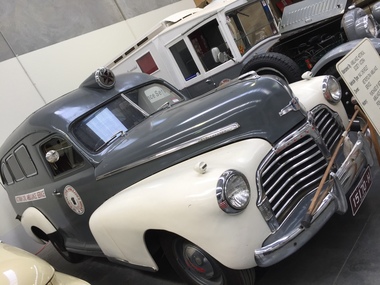
... Air Force during the Second World War. Purchased by Metropolitan Ambulance Service in 1989 from a Military Museum. This vehicle appeared in the filming of the movie "The White Mouse" (the story of Nancy Wake, French Resistance worker in the second World War). ...Air Force during the Second World War. Purchased by Metropolitan Ambulance Service in 1989 from a Military Museum. This vehicle appeared in the filming of the movie "The White Mouse" (the story of Nancy Wake, French Resistance worker in the second World War). ...This vehicle is a Chevrolet but was fitted out as an ambulance at Fisherman's Bend, near Melbourne, Victoria by General Motors Holden. It was used by the Royal Australian Air Force during the Second World War. Purchased by Metropolitan Ambulance Service in 1989 from a Military Museum. This vehicle appeared in the filming of the movie "The White Mouse" (the story of Nancy Wake, French Resistance worker in the second World War). It also appeared in the film "Blonde" (the life of Marilyn Monroe). Four-wheeled vehicle used as ambulance. Body painted grey and cream, chrome radiator and bumpers.Vehicle registration number 15170-Hchevrolet, general motors holden, fisherman's bend, ambulance, motor vehicle, raaf (royal australian air force), second world war -
Moorabbin Air Museum
Document (item) - CAC Collection - Military Standard - Light Fixed And Rotary-Wing Aircraft Crash Resistance
... Moorabbin Air Museum Moorabbin Airport 12 First Street Moorabbin melbourne Department Of Defence USA MIL-STD-1290A9(AV) CAC Collection - Military Standard - Light Fixed And Rotary-Wing Aircraft Crash Resistance Document CAC Collection - Military Standard - Light Fixed And Rotary-Wing Aircraft Crash Resistance ...Department Of Defence USA MIL-STD-1290A9(AV) -
Moorabbin Air Museum
Booklet (item) - Determination Of The Fatigue Resistance Of Aircraft Wings By Full Scale Testing
... Moorabbin Air Museum Moorabbin Airport 12 First Street Moorabbin melbourne By A.O.Payne ARL Melbourne - Reference To Mustang And CA-12 Boomerang Tests Determination Of The Fatigue Resistance Of Aircraft Wings By Full Scale Testing Booklet Determination Of The Fatigue Resistance Of Aircraft Wings By Full Scale Testing ...By A.O.Payne ARL Melbourne - Reference To Mustang And CA-12 Boomerang Tests -
Moorabbin Air Museum
Book - Tunned diodes, Basic Theory And Application Of Tunnel Diodes
... Moorabbin Air Museum Moorabbin Airport 12 First Street Moorabbin melbourne Tunnel Diodes Tunnel diodes ciirca early 1960s Overview of the physics of electron tunneling with explanation of amplification & oscillation using negative resistance Basic Theory And Application Of Tunnel Diodes Book Tunned diodes ...Overview of the physics of electron tunneling with explanation of amplification & oscillation using negative resistancenon-fictionOverview of the physics of electron tunneling with explanation of amplification & oscillation using negative resistancetunnel diodes ciirca early 1960s -
Moorabbin Air Museum
Manual (Item) - Weston Instruments General Service Instructions for models 727 and 728 Ratio Type Resistance Thermometers
... Moorabbin Air Museum Moorabbin Airport 12 First Street Moorabbin melbourne Weston Instruments General Service Instructions for models 727 and 728 Ratio Type Resistance Thermometers Manual Weston Instruments General Service Instructions for models 727 and 728 Ratio Type Resistance Thermometers ... -
Moorabbin Air Museum
Manual (Item) - Sangamo Weston Model S.110 Resistance Thermometer Element Overhaul Manual
... Moorabbin Air Museum Moorabbin Airport 12 First Street Moorabbin melbourne Sangamo Weston Model S.110 Resistance Thermometer Element Overhaul Manual Manual Sangamo Weston Model S.110 Resistance Thermometer Element Overhaul Manual ... -
 Geoffrey Kaye Museum of Anaesthetic History
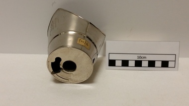
Equipment - Inhaler, Ether, Dewee, 1901
... The patient breathes air down through the variable orifice over the surface of ether and in through the variable orifice over the surface of ether and in through the inspiratory valve. Exhalation was by means of the expiratory valve placed in the centre of the mask. All channels are extremely small and would offer considerable resistance...The patient breathes air down through the variable orifice over the surface of ether and in through the variable orifice over the surface of ether and in through the inspiratory valve. Exhalation was by means of the expiratory valve placed in the centre of the mask. All channels are extremely small and would offer considerable resistance ...This is a simple metal mask with an ether chamber surmounting it. The patient breathes air down through the variable orifice over the surface of ether and in through the variable orifice over the surface of ether and in through the inspiratory valve. Exhalation was by means of the expiratory valve placed in the centre of the mask. All channels are extremely small and would offer considerable resistance to respiration.Metal inhaler with shaped rim edgeEngraved by hand into side of mask: DEWEE'S ETHER / INHALER.. 1901. Stamped into side of mask: J.E. LEECO / PATD. NOV. 12-1901 / 400ether, inhaler, ramsay, dewee, leeco -
 Royal Australian and New Zealand College of Obstetricians & Gynaecologists (RANZCOG)
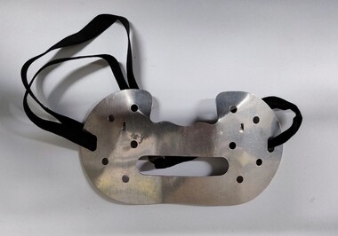
Equipment - Protective metal dust mask associated with Dr Lorna Lloyd-Green
... air intake. There are five round holes on either side of the mask, likely included to decrease the mask's breathing resistance for the wearer. ...air intake. There are five round holes on either side of the mask, likely included to decrease the mask's breathing resistance for the wearer. ...This style of mask was developed in Britain and began to appear from the 1930s, though original models may have been produced in the 1920s. Various patents for this style of mask were still being filed in the 1960s, so they were used for a considerable period of time. It is possible that the original filter pads for these masks contained asbestos, as they supposedly utilised 'fire proof' materials. Asbestos was already in use in other British respirator masks at this time. Original cataloguing information believed this item to be an eye shield, but further research has indicated that this is not the case.Mask consists of a metal plate designed to cover the lower half of the face. There is a recess along the top edge of the plate designed for the nose to sit in. There is a large oblong opening with rounded corners at the centre of the mask, which is a mouth opening to assist speech and is the main air intake. There are five round holes on either side of the mask, likely included to decrease the mask's breathing resistance for the wearer. Rounded slots at each edge of the mask are threaded through with an elastic strap, used for attaching the mask to the face. This mask would have been used with a filtering pad attached, but the pad is missing.