Showing 7 items matching "automatic circuit breaker"
-
 Melbourne Tram Museum
Document - Instruction, The British Westinghouse Electric & MFG Co. Ltd, "Parts of Westinghouse Automatic Circuit Breaker Tramway Type", c1920
... "Parts of Westinghouse Automatic Circuit Breaker Tramway Type"...Instruction - 12 pages + brown covers, centre stapled titled "Parts of Westinghouse Automatic Circuit Breaker Tramway Type", Style Nos. 5401, 5402, 5403 and 5404. ...circuit breaker, lists all parts, shows images of the various parts. Has a list of company offices on the last page and the Westinghouse UK printing bureau logo. "Parts of Westinghouse Automatic ...Instruction - 12 pages + brown covers, centre stapled titled "Parts of Westinghouse Automatic Circuit Breaker Tramway Type", Style Nos. 5401, 5402, 5403 and 5404. Part list B6009. Shows images of the circuit breaker, lists all parts, shows images of the various parts. Has a list of company offices on the last page and the Westinghouse UK printing bureau logo.trams, tramways, electrical engineering, electrical equipment, westinghouse, instructions, maintenance -
 Ballarat Tramway Museum
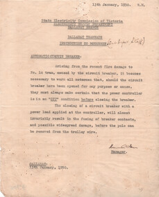
Document, State Electricity Commission of Victoria (SECV), "Instruction to Motormen - Automatic Circuit Breaker", 13/1/1950
... "Instruction to Motormen - Automatic Circuit Breaker"...Instruction to Ballarat motormen and depot staff dated 13/1/1950, about ensuring the controller was closed in the off position before opening the automatic circuit breaker. Appears this was not done on tram 14 and a fire resulted. ...circuit breaker operated. SECV trams tramways faulty equipment tram 14 Fire Circuit Breakers Controllers "and depot staff" hand written in ink along title. Notice type on quarto paper. "Instruction to Motormen - Automatic ...Instruction to Ballarat motormen and depot staff dated 13/1/1950, about ensuring the controller was closed in the off position before opening the automatic circuit breaker. Appears this was not done on tram 14 and a fire resulted. Significant damage can result of the action. When the tram was rewired during 2024, this fire damage was apparent. Signed by Mr. Farr.Yields information about a fire in tram 14 as the result of the controller being left open and the circuit breaker operated.Notice type on quarto paper."and depot staff" hand written in ink along title.secv, trams, tramways, faulty equipment, tram 14, fire, circuit breakers, controllers -
 Melbourne Tram Museum
Document - Instruction, The British Westinghouse Electric & MFG Co. Ltd, "Parts of Westinghouse No. 46 and 46M Tramway Motors”, “Parts of Westinghouse No. 49B Tramway Motor”, “Parts of Westinghouse No. 200 Tramway Motor”, “Parts of Westinghouse Nos 90 and 90M Controllers”, “Parts of Westinghouse Automatic Circuit breaker tramway type”, 1900's
... "Parts of Westinghouse No. 46 and 46M Tramway Motors”, “Parts of Westinghouse No. 49B Tramway Motor”, “Parts of Westinghouse No. 200 Tramway Motor”, “Parts of Westinghouse Nos 90 and 90M Controllers”, “Parts of Westinghouse Automatic Circuit breaker tramway type”...3700.1 – British Westinghouse Electric and Manufacturing Co – Parts Catalogue B 6004, “Parts of Westinghouse No. 46 and 46M Tramway Motors” – 2nd Edition – 20 pages centre stapled. 3700.2 - British Westinghouse Electric and Manufacturing Co – Parts Catalogue B 6005, “Parts of Westinghouse No. 49B Tramway Motor” – 2nd Edition – 20 pages centre stapled. 3700.3 – British Westinghouse Electric and Manufacturing Co – Parts Catalogue B 6006, “Parts of Westinghouse No. 200 Tramway Motor” – Oct 1904 – 20 pages centre stapled. 3700.4 – British Westinghouse Electric and Manufacturing Co – Parts Catalogue, “Parts of Westinghouse Nos 90 and 90M Controllers” – 12 pages from a 24 page document, has Electric Supply Co. stamp on the cover. 3700.5 - 3700.2 – British Westinghouse Electric and Manufacturing Co – Parts Catalogue, “Parts of Westinghouse Automatic Circuit breaker tramway type”, 8 pages centre stapled of a larger document....."Parts of Westinghouse No. 46 and 46M Tramway Motors”, “Parts of Westinghouse No. 49B Tramway Motor”, “Parts of Westinghouse No. 200 Tramway Motor”, “Parts of Westinghouse Nos 90 and 90M Controllers”, “Parts of Westinghouse Automatic Circuit breaker tramway type” Document Instruction The British Westinghouse Electric & MFG Co. ...3700.1 – British Westinghouse Electric and Manufacturing Co – Parts Catalogue B 6004, “Parts of Westinghouse No. 46 and 46M Tramway Motors” – 2nd Edition – 20 pages centre stapled. 3700.2 - British Westinghouse Electric and Manufacturing Co – Parts Catalogue B 6005, “Parts of Westinghouse No. 49B Tramway Motor” – 2nd Edition – 20 pages centre stapled. 3700.3 – British Westinghouse Electric and Manufacturing Co – Parts Catalogue B 6006, “Parts of Westinghouse No. 200 Tramway Motor” – Oct 1904 – 20 pages centre stapled. 3700.4 – British Westinghouse Electric and Manufacturing Co – Parts Catalogue, “Parts of Westinghouse Nos 90 and 90M Controllers” – 12 pages from a 24 page document, has Electric Supply Co. stamp on the cover. 3700.5 - 3700.2 – British Westinghouse Electric and Manufacturing Co – Parts Catalogue, “Parts of Westinghouse Automatic Circuit breaker tramway type”, 8 pages centre stapled of a larger document...4 - has the stamp of the "Electric Supply Company of Victoria"trams, tramways, westinghouse, instructions, maintenance, controllers, motors, circuit breakers -
 Ballarat Tramway Museum
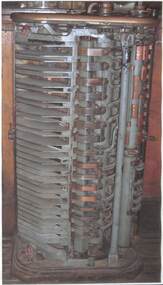
Equipment - Equipment - Controller, Tram Controller, Possible from Tram 22
... ...automatic circuit breaker...The controller is supplied with power via a current limiting automatic circuit breaker. It has a handle on top and this turns a drum fitted with insulated copper segments. ...The controller is supplied with power via a current limiting automatic circuit breaker. It has a handle on top and this turns a drum fitted with insulated copper segments. ...Controller from an old tram, possible Tram 22. Appears to be a typical parallel drum controller with the casing removed. The arc shield is in place. With this swung back the drum segments and fingers are revealed. The controller is supplied with power via a current limiting automatic circuit breaker. It has a handle on top and this turns a drum fitted with insulated copper segments. There is usually a star wheel and roller which ensures that the drum advances in notches to match the drum segments.Large laminated photograph of a tram controller c1920controller, tramcars, parallel drum controller, automatic circuit breaker, handle, star wheel -
 Melbourne Tram Museum
Letter - Correspondence, Melbourne & Metropolitan Tramways Board (MMTB), "Trolley Buses", 1922-36
... Blueprint – drawing 2810 – DK 26 Motor Blueprint – No. 1312D – controller diagram Pamphlet – EE – tramcar Type D automatic circuit Breakers. Publication No. 230, dated 9/1920. ...Blueprint – drawing 2810 – DK 26 Motor Blueprint – No. 1312D – controller diagram Pamphlet – EE – tramcar Type D automatic circuit Breakers. Publication No. 230, dated 9/1920. ...File containing correspondence between the MMTB Chief Engineer Mr. Strickland and various companies, including Railless Ltd, Australian General Electric, English Electric / Dick Kerr and its UK consultants Heap and Digby (H&D) between the period August 1922 and August 1936. Includes drawings, technical specifications, some of which are duplicated in the Reg Item 535 file. For a listing of the contents of this file and of Reg Item 535, see Related Documents - htd535-536list.pdf Item 536 - Trolley Buses Listed from top of file, in order found. Letters generally to/from MMTB Chief Engineer. Date Type Notes 7/8/1936 Letter from TE Barnes – re Bremen Germany Steam Omnibus. Three pages. On foolscap paper – rest quarto. Has been damaged. 3/2/1926 Letter from Bruce Henderson re transport in the Glen Eira Rd area – poor private bus. 25/10/1925 Letter to G. Higgins, regarding a paper he had presented and printed in Australian Municipal Journal about transport around Melbourne, predicted the demise of trams, trains. Notes Spencer St bridge. Copy of paper is pinned with letters. 28/819/22 Copy of letter to H&D from AEC (see above) Includes the Mexborough test gradient drawing. Undated Pamphlet from Railless Limited about Birmingham’s new trolley buses. 16/3/1923 Extract from Electric Railway and Tramway Journal – wages of trolleybus drivers not getting paid extra in Bradford. Two copies pinned together. 9/4/1923 Letter from H&D re pamphlet exchange You should have had it! 23/2/1923 Letter to H&D asking for information. Has a note re the Board’s attitude towards motor buses. 28/8/1922 to 24/23 Series of letters pinned together with L. de Koenneritz regard trolley buses and Paris. Noted that the MMTB did not have the legislative power to run trolley buses. 15/2/1922 to 10/4/23 Series of letters pinned together with the Aust. GE regarding trolley buses and references to their operation in journals. 10/1/1923 Letter from H&D re request for information on driving gear of Railless Ltd. vehicles 23/2/1923 Letter to H&D re above. 23/2/1923 Sheet of paper on “Steads Review” paper – pamphlet not yet to hand. 8/11/1922 to 10/1/1923 Series of letters with H&D pinned together asking for Railless driving gear – reluctant to provide. 26/9/1922 Letter from H&D, with copy of letter from English Electric enclosing materials regarding Trolley Bus equipment. Note much of this material is the same as that in Reg Item 535 contained within the green cloth tape. Performance curves for DK 26B motor Blueprint – 4449 – outline of controller DK, Type D, form B. Specification for DK 26B trolley motor. Blueprint – drawing 2810 – DK 26 Motor Blueprint – No. 1312D – controller diagram Pamphlet – EE – tramcar Type D automatic circuit Breakers. Publication No. 230, dated 9/1920. Ditto, Form A, drawings No 3565, 1/1/19. Performance curves for DK85A motor Blueprint – P2002M034 – DK85 Motor. EE specification for Traction Motor DK85 Modified from a tram motor. Blueprint – EE drawing – P2002M036 – DK85 motor with ball bearings. EE blueprint P2102F021, traction control wiring for form D controller. EE blueprint P2103F033 – outline of controller type SE1, form C and D. EE blueprint P2102Z011 – wiring diagram for type SE1 form controller. EE blueprint – P2102F025 – diagram of connections (wiring) for Type SE1, form D controller.trams, tramways, trolley buses, melbourne, mmtb, aec, heap and digby, english electric, railless, dick kerr, general electric -
Melbourne Tram Museum
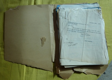
Letter - Correspondence, Melbourne & Metropolitan Tramways Board (MMTB), "Trolley Buses", 1922-23
... Blueprint – drawing 2810 – DK 26 Motor Performance curves for above motor Blueprint – No. 1312D – controller diagram Pamphlet – EE – tramcar Type D automatic circuit Breakers. Publication No. 230, dated 9/1920. ...Blueprint – drawing 2810 – DK 26 Motor Performance curves for above motor Blueprint – No. 1312D – controller diagram Pamphlet – EE – tramcar Type D automatic circuit Breakers. Publication No. 230, dated 9/1920. ...File containing correspondence between the MMTB Chief Engineer Mr. Strickland and various companies, including Railless Ltd, Australian General Electric, English Electric / Dick Kerr and its UK consultants Heap and Digby between the period August 1922 and January 1923. Includes drawings, technical specifications and a book titled "AEC Railless Trolley Bus Specification", date stamped 15/8/1922. For a scan of this document see htd535-trolleybus.pdf (imaging not working correctly for this database as at 9-8-14) For a listing of the contents of this file and of Reg Item 535, see Related Documents - htd535-536list.pdf Item 535 - Trolley Buses Listed from top of file, in order found. Letters generally to/from MMTB Chief Engineer. Date Type, contents and notes 18/11/1922 Letter to Metro Vickers from Chief Engineer re Railless trams 12/1/1923 Letter to Aust GE re railless trams Not likely to proceed at this time. 11/1/1923 Letter from Aust GE Co. providing photographs, drawings, BTH, pamphlets, and general information. Includes photo of Tee-side trolley bus No. 17. No other papers with this item. 6/9/1922 Letter to Aust. GE asked for particulars and drawings of motor omnibuses These three items pinned together. 5/9/1922 Letter to Chief Engineer from Aust. GE provided up to date figures on BTH Railless vehicles. These three items pinned together. 31/8/1922 Letter to Aust GE returning folded of data in relation to petrol and petrol electric cars. These three items pinned together. 24/10/1922 Letter to Heap & Digby, thanks for information, but unlikely to use trolley buses due to poor road conditions where they could be used in terms of revenue. 14/9/1922 Letter from Heap & Digby, inclosing photos of Railless Ltd vehicles supplied to Bloemfontein South Africa and testing. These two items clipped together with drawing No. SK 14-8, showing Mexborough gradients. 28/8/1922 Letter from AEC to Heap & Digby re trolley buses, construction costs and practicality of shipping these to Aust. Includes the Mexborough test results. These two items clipped together with drawing No. SK 14-8, showing Mexborough gradients. 3/8/1922 to 31/10/22 Correspondence between MMTB and H&D regarding the Bloemfontein vehicles. Pinned together. 17/11/1922 Letter from Metro Vickers to MMTB providing details (no photos or drawings) of trolley buses – four pages. 18/1/1923 Letter to H&D thanking him for information and a paper ready by a Mr. Munro. 31/8/1922 Letter to Metro Vic – Melbourne asking whether Westinghouse had developed standard lines of motors for railless cars. 4/10/1922 Letter to Aust GE thanking for info. 2/10/1922 Letter from Aust GE providing two cuttings about railless vehicles in Birmingham and the cost of tram track construction. Papers Contained within a green strip of cloth. 26/9/1922 Letter from H&D providing info from EE – Dick Kerr Preston works equipment used by Railless Ltd. EE Specification for DK 26B Trackless trolley motors 18/9/1922 Letter from EE to H&D providing info on 20HP motors, 40HP, and other information. Blueprint – drawing 2810 – DK 26 Motor Performance curves for above motor Blueprint – No. 1312D – controller diagram Pamphlet – EE – tramcar Type D automatic circuit Breakers. Publication No. 230, dated 9/1920. Ditto, Form A, drawings No 3565, 1/1/19. Performance curves – blueprint – Type DK85A Blueprint – 4449 – outline of controller DK, Type D, form B. Blueprint – P2002M034 – DK85 Motor. EE specification for Traction Motor DK85 Modified from a tram motor. EE blueprint P2102F021, traction control wiring for form D controller. EE blueprint P2103F033 – outline of controller type SE1, form C and D. EE blueprint P2102Z011 – wiring diagram for type SE1 form controller. Performance curves for DK85A motor. EE blueprint – P2102F025 – diagram of connections (wiring) for Type SE1, form D controller. Blueprint – EE drawing – P2002M036 – DK85 motor with ball bearings. Single documents. Date Type Notes 27/9/1922 Letter to H&D acknowledging AEC Trackless trolley bus specification. 15/8/1922 Letter from H&D forwarding above specification String bound book – AEC Railless Trolley Bus Specification – stamped 15/8/22 Scanned as a separate document. 4/9/1922 Letter from Metro Vic. Melbourne advising that they have no information on Westinghouse Motors for use in railless cars, but seeking same.trams, tramways, trolley buses, melbourne, mmtb, aec, heap and digby, english electric, railless, dick kerr, general electric -
 Kiewa Valley Historical Society
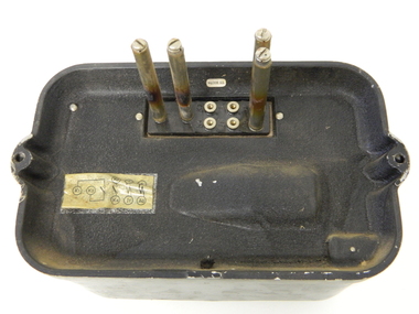
Relay Protection Instrument, Circa 1950's
... The front glass enclosed meter and recorder allows for the identification and automatic disconnection of any faulty equipment connected to the main power generator. This equipment acts similarly to a modern day circuit breaker found on the electrical circuit boards of residential homes....The front glass enclosed meter and recorder allows for the identification and automatic disconnection of any faulty equipment connected to the main power generator. This equipment acts similarly to a modern day circuit breaker found on the electrical circuit boards of residential homes. ...This protection relay apparatus (a large electrical fuse), which permits the easy monitoring and disconnection of faulty electrical apparatus connected to the large SEC Victoria Hydro Scheme's electrical power producing generators. These generators are powered by the hydro force of "stored" water at a higher altitude. The establishment of both the NSW and Victorian Hydro Schemes was achieved from the early 1900's to the 1960's. At this point in time the need for additional power sources to quench both an industrial and domestic demand for electricity was purely an economic and not and environmental (carbon reduction) factor. This hydro scheme was instigated by "the Government of the day" as a bold move and was the major force of the World War II refugee and "technical" workforce inclusion of skilled and unskilled migration into the Australian environment. Although this mass "invasion" of workers with families was thought of in some circles as intrusive, the expansion of population post war years and its integration into the Australian rural sector, produced the multi- lingual multi-cultural diversity of later years.This protection relay is very significant to the Kiewa Valley as its use was introduced during the Kiewa Hydro Scheme. Although only a small apparatus it was part of the explosion of human resources into the valley. This influx of population transformed the region from that of a basically quiet rural region to one which evolved into both an industrial and a larger residential community. This evolution in the valley created a change, not only in the "physical" landscape but also the socio-economic expansion which permitted other "tourist" based industries into the valley.This protection relay unit has a black painted metal shell with four copper enclosed "prongs" fastened to the rear of the housing(from a bake-lite plate) . Between these "prongs" are four "empty" points allowing additional "screw on" bases. The front glass enclosed meter and recorder allows for the identification and automatic disconnection of any faulty equipment connected to the main power generator. This equipment acts similarly to a modern day circuit breaker found on the electrical circuit boards of residential homes.On the top section of the front panel "ASEA" to the left "Made in Sweden" and to the right "Frabrique en Suede" below this "RIS" below this a graph and next to it two columns of numbers and a pointer for each setkiewa hydro electricity scheme, victorian state electricity commission, relays, generators