Showing 8 items matching "deflections"
-
 National Vietnam Veterans Museum (NVVM)
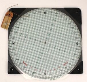
Instrument - Plotting Board, M19
... The user can determine deflection, azimuth, and range....The user can determine deflection, azimuth, and range. plotting board M19 mortar North, South, East , West / Rotating disc calibrated with numbers The M19 plotting board consists of a rotating disk of transparent plastic and a removable range arm (missing), both attached to a flat round white grid base. ...Standard issue item as used by Australian servicemen during conflict in Vietnam (1962-1973). Plotting boards are a secondary means of firing control for all mortars. The user can determine deflection, azimuth, and range.The M19 plotting board consists of a rotating disk of transparent plastic and a removable range arm (missing), both attached to a flat round white grid base.North, South, East , West / Rotating disc calibrated with numbersplotting board, m19, mortar -
 Bendigo Military Museum
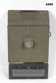
Equipment - PERISCOPE, TANK, C.1942
... that adjust elevation and deflection. The rear panel has a large ?? knob....that adjust elevation and deflection. The rear panel has a large ?? knob. ...Believed to have come from a Sherman Tank, c. WWII.Main frame is rectangular, painted jungle green. Bottom viewer is metal with glass window. Top viewer is made of bakelite with glass window. On the rear viewer side are 2 dials and a brass ?? that adjust elevation and deflection. The rear panel has a large ?? knob.The side has a plaque "PERISCOPE M4 - MINNEAPOLIS - HONEYWELL REGULATOR COMPANY. No 54340 1942 USA"wwii, sherman tank, periscope -
 Port Fairy Historic Lifeboat Station
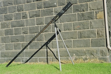
Equipment - Rocket Machine, c.1870
... The rocket machine allowed the rocket to be launched into a calculated trajectory, and with estimated deflection to allow for wind. The rockets were widely used to carry the first (connecting) line to the wreck. ...The rocket machine allowed the rocket to be launched into a calculated trajectory, and with estimated deflection to allow for wind. The rockets were widely used to carry the first (connecting) line to the wreck. ...The Boxer rocket carried a light line from shore to the wreck. The rocket machine allowed the rocket to be launched into a calculated trajectory, and with estimated deflection to allow for wind. The rockets were widely used to carry the first (connecting) line to the wreck. The rocket machine was fundamental for the successful commencement of a breeches buoy rescue. The machine could project the line beyond the effective rescue distance, and allowed the initial and vital physical connection between wreck and the shore. Boxer rocket launcher, a triangular frame to carry the rocket to preferred firing position and angle, with pendulum arrow, black exterior and grey legs (2 of) -
 Port Fairy Historic Lifeboat Station
Equipment - Rocket Machine
... The rocket machine allowed the rocket to be launched into a calculated trajectory, and with estimated deflection to allow for wind. The rockets were widely used to carry the first (connecting) line to the wreck....The rocket machine allowed the rocket to be launched into a calculated trajectory, and with estimated deflection to allow for wind. The rockets were widely used to carry the first (connecting) line to the wreck. ...The Boxer rocket carried a light line from shore to the wreck. The rocket machine allowed the rocket to be launched into a calculated trajectory, and with estimated deflection to allow for wind. The rockets were widely used to carry the first (connecting) line to the wreck.The rocket machine was fundamental for the successful commencement of a breeches buoy rescue. The machine could project the line beyond the effective rescue distance, and allowed the initial and vital physical connection between wreck and the shore.Boxer rocket launcher, a triangular frame to carry the rocket to preferred firing position and angle, with pendulum arrow, black exterior and grey legs (2 of) -
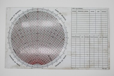 National Vietnam Veterans Museum (NVVM)
Instrument - Plotting Board, M16
... A circle marked with grid lines is printed on the base and a vernier for finding azimuth deflections in along top edge. Rotating disc pivots at the centre atop the disc with distances measured radially form 0 at the centre to 3400 metres around the rim range form 0-6400 metres. ...A circle marked with grid lines is printed on the base and a vernier for finding azimuth deflections in along top edge. Rotating disc pivots at the centre atop the disc with distances measured radially form 0 at the centre to 3400 metres around the rim range form 0-6400 metres. ...Standard issue item as used by Australian servicemen during the conflict in Vietnam. A plotting board is a mechanical device used as part of a firing control system to track the observed course of a target, project its future position, and derive the azimuth (or direction) and range needed to direct the fire of the guns of a battery to hit that target.White plastic base. A circle marked with grid lines is printed on the base and a vernier for finding azimuth deflections in along top edge. Rotating disc pivots at the centre atop the disc with distances measured radially form 0 at the centre to 3400 metres around the rim range form 0-6400 metres. A scale pivoted at the centre assists in reading distances.Nth and Sth top and bottom on rotating disc. East and West in centre distances in black on outer of disc. Distances in green on inner North, South, East, West. Varn W left bottom of disc. varn E on right bottom of disc.plotting board, m16 -
 Moorabbin Air Museum
Document - Wamira A10 Documents and drawings
... ATB B3-4 Box X85 A10 Wamira GAF Report on position of flutter analysis Wing electrics A10-J81-024 Flap – detail design document Trainer program undercarriage Wing static test 20.11.85 Strain gauge results Box 3 Wing static test deflections 22.1..85 Wing static test 7.11.85 Program to estimate loading effects due to continuous atmospheric turbulence GAF report on position of flutter analysis Wing static test 20.11.85 Strain gauge results Box 2 Mock up photos 3.9.84 Aeroelastic Design Philosophy ...Moorabbin Air Museum Moorabbin Airport 12 First Street Moorabbin melbourne ATB B3-4 Box X85 A10 Wamira GAF Report on position of flutter analysis Wing electrics A10-J81-024 Flap – detail design document Trainer program undercarriage Wing static test 20.11.85 Strain gauge results Box 3 Wing static test deflections 22.1..85 Wing static test 7.11.85 Program to estimate loading effects due to continuous atmospheric turbulence GAF report on position of flutter analysis Wing static test 20.11.85 Strain gauge results Box 2 Mock up photos 3.9.84 Aeroelastic Design Philosophy Document Wamira A10 Documents and drawings ... -
Moorabbin Air Museum
Book - Aircraft structures, Airplane Structures Vol. 1 and Vol. 2
... ...Deflections...Stresses Design procedure Torsion Grap Truss analysis Graphical methods Connections Deflections Overview in 2 volumes of aircraft structures, circa 1943 2 volumes Airplane Structures Vol. 1 and Vol. 2 Book Aircraft structures ...Overview in 2 volumes of aircraft structures, circa 19432 volumes non-fictionOverview in 2 volumes of aircraft structures, circa 1943beams & columns, tension fields, shell analysis, rings, loads, torsional column failure., stresses, design procedure, torsion, grap, truss analysis, graphical methods, connections, deflections -
Moorabbin Air Museum
Document (item) - Wamira NIA E37 Documents and drawings
... NIA E37 Wamira Engine options for bid Sept 85 CA34-S556-12 Windscreen and canopy finite element model CA34-S556-10 Canopy frame stressing CA34-S556-14 Windscreen transparency stressing CA34-S556-15 Windscreen structure stressing CA34-S556-11 Canopy mechanisms stressing Bid data Estimates (detail and task plans Hawker DH A10B proposal to Dept of Defence Vol 2, Vol 5, Vol 6 Wing static test strain gauge curves Box 1 Wing static testing deflections Wing static test SC curves Box II Wing static test SC Curves Box 3 ATR box installation rear fuselage AFTIS orange boxes in rear cockpit Barry mounts trays and isolators Flight data recorder installation AFTIS equipment in rear cockpit ...Moorabbin Air Museum Moorabbin Airport 12 First Street Moorabbin melbourne NIA E37 Wamira Engine options for bid Sept 85 CA34-S556-12 Windscreen and canopy finite element model CA34-S556-10 Canopy frame stressing CA34-S556-14 Windscreen transparency stressing CA34-S556-15 Windscreen structure stressing CA34-S556-11 Canopy mechanisms stressing Bid data Estimates (detail and task plans Hawker DH A10B proposal to Dept of Defence Vol 2, Vol 5, Vol 6 Wing static test strain gauge curves Box 1 Wing static testing deflections Wing static test SC curves Box II Wing static test SC Curves Box 3 ATR box installation rear fuselage AFTIS orange boxes in rear cockpit Barry mounts trays and isolators Flight data recorder installation AFTIS equipment in rear cockpit Document Wamira NIA E37 Documents and drawings ...