Showing 14 items matching "load control system"
-
 Moorabbin Air Museum
Manual - Lockheed Hercules technical training, Customer Training Power Plant APU Supplement
... ...Load control system...Moorabbin Air Museum Moorabbin Airport 12 First Street Moorabbin melbourne Lockheed Hercules technical training APU - general Gas turbine operating Electrical controls Functions Airflow path Lubrication system Fuel system Load control system .Operation/inspection/maintenance Technical overview of Hercules auxiliary power unit, circa 1976 Customer Training Power Plant APU Supplement Manual Lockheed Hercules technical training ...Technical overview of Hercules auxiliary power unit, circa 1976non-fictionTechnical overview of Hercules auxiliary power unit, circa 1976apu - general, gas turbine operating, electrical controls, functions, airflow path, lubrication system, fuel system, load control system, .operation/inspection/maintenance -
Moorabbin Air Museum
Manual (Item) - Checklist - Suu-25E/A Flare Dispenser
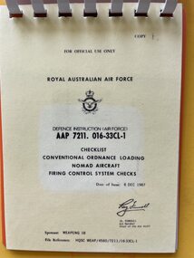
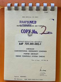
... Description: CHECKLIST Conventional Ordnance Loading Porter Aircraft Firing Controls System Checks AAP: 7211.001-33CL-1 Date: 05 Aug 1986 Author: RAAF Amended to AL: Publisher: RAAF Pages: 44 Binding: Ring Content/Keywords Level of Importance: . ...Moorabbin Air Museum Moorabbin Airport 12 First Street Moorabbin melbourne Description: CHECKLIST Conventional Ordnance Loading Porter Aircraft Firing Controls System Checks AAP: 7211.001-33CL-1 Date: 05 Aug 1986 Author: RAAF Amended to AL: Publisher: RAAF Pages: 44 Binding: Ring Content/Keywords Level of Importance: . ...Description: CHECKLIST Conventional Ordnance Loading Porter Aircraft Firing Controls System Checks AAP: 7211.001-33CL-1 Date: 05 Aug 1986 Author: RAAF Amended to AL: Publisher: RAAF Pages: 44 Binding: Ring Content/Keywords Level of Importance: . -
 Bendigo Military Museum
Photograph - RA Svy Project C4 Aerodist Operation, Eastern & Western Arnhem Land, NT, 1967, 1968
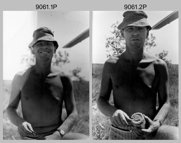
... load carrying capacity of up to about 500 pounds. By comparison, one Aerodist team including two people weighed up to 1,500 pounds. In 1968, after completion of the Kimberley Aerodist Operation project, the Aerodist system in VH-EXX was immediately deployed to western-Arnhem Land NT for Central Comd Fd Svy Unit (Adelaide - Major Don Ridge) to complete the mapping control across northern NT from mid-July to October. ...load carrying capacity of up to about 500 pounds. By comparison, one Aerodist team including two people weighed up to 1,500 pounds. In 1968, after completion of the Kimberley Aerodist Operation project, the Aerodist system in VH-EXX was immediately deployed to western-Arnhem Land NT for Central Comd Fd Svy Unit (Adelaide - Major Don Ridge) to complete the mapping control across northern NT from mid-July to October. ...This is a set of 26 photographs of Royal Australian Survey Corps (RA Svy) personnel from Central Comd Fd Svy Unit (Adelaide) on Aerodist survey operation - Project C4 in Eastern Arnhem Land, Northern Territory in 1967 (photos .4P to .26P) and in Western Arnhem Land, Northern Territory in 1968 (photos .1P to .3P). Photos of personnel were taken either at the operations base at Numbulwar or the main base at Gove (Nhulunbuy). RA Svy conducted nineteen Aerodist operations for 12 years from 1964 to 1975. Aerodist MRC2 was a tellurometer-based system adapted for aircraft to accurately measure distances between non-intervisible ground survey stations, using the aircraft as an intermediate station. Lower order geodetic results could be achieved by survey network trilateration. The measured distances between stations formed survey networks from which each station’s latitude and longitude was computed. Aerodist MRC2 was RA Svy’s major horizontal control survey tool for mainly medium scale topographic mapping (scale 1:100,000 Class A being spatially accurate to within 50 metres) in PNG, northern NT, north-west WA, Kalimantan Barat (West) Indonesia, Sumatra Indonesia, Gulf of Carpentaria and Cape York, QLD. In 1967, the Aerodist MRC2 Master equipment was installed in the aircraft featured in this set of photos, Executive Air Services’ (Essendon VIC) Grand Aero Commander VH-EXX. It was the same aircraft type and company contracted to Division of National Mapping for Aerodist MRC2 surveys. From July to October 1967 the aircraft was attached to Central Comd Fd Svy Unit (Adelaide - Major Don Ridge) on Project C4 eastern-Arnhem Land NT, where 317 Aerodist lines measuring 17,300 line miles were successfully completed. This was the most productive Aerodist project thus far. The most common helicopter used by RA Svy up to 1972 was the civilian Bell 47G-2 and the Sioux Light Observation Helicopters (LOH), the Australian Army’s equivalent featured in this photo set. These light observation helicopters had a limiting load carrying capacity of up to about 500 pounds. By comparison, one Aerodist team including two people weighed up to 1,500 pounds. In 1968, after completion of the Kimberley Aerodist Operation project, the Aerodist system in VH-EXX was immediately deployed to western-Arnhem Land NT for Central Comd Fd Svy Unit (Adelaide - Major Don Ridge) to complete the mapping control across northern NT from mid-July to October. The Aerodist MRC2 Remote antenna seen in Photos .24P to .26P is mounted on a 20 foot pole tower. The antenna direction was controlled by wires/ropes to the two arms under the dish at right angles. The antenna elevation could be changed to the vertical for aircraft height checks as seen in photo .25P. Source: Royal Australian Survey Corps – Aerodist Years 1964-1975 by Peter Jensen. Refer to Item 6449.30P for more photos taken during these Aerodist survey operations.This is a set of 26 photographs of Royal Australian Survey Corps (RA Svy) personnel on Aerodist survey operations in Eastern Arnhem Land, Northern Territory in 1967 and Western Arnhem Land, Northern Territory in 1968. The photographs are on 35mm negative film and scanned at 96 dpi. They are part of the Army Survey Regiment’s Collection. .1) to .2) – Photo, black & white, 1968, unidentified soldier with an opened can of food, possibly bully beef. .3) – Photo, black & white, 15 Aug 1968, aerial view of terrain taken from a helicopter in vicinity of MILINGIMBI SIERRA. .4) – Photo, black & white, 1967, aerial view of an island taken from a helicopter. .5) & .6) – Photo, black & white, 1967, unidentified soldier driving a Haflinger 4x4 Light utility vehicle with trailer. .7) – Photo, black & white, 1967, unidentified surveyors taking vertical measurements with a leveling instrument and staff. .8) – Photo, black & white, 1967, Australian Army Sioux Light Observation Helicopter (LOH) with float removed. .9) to .11) – Photo, black & white, 1967, Australian Army Sioux Light Observation Helicopter (LOH) with floats. .12) – Photo, black & white, 1967, civilian Bell 47G-2 helicopter (Australian Army Sioux LOH equivalent) refuelled. .13) – Photo, black & white, 1967, survey station on coastline surrounded by white plastic aerial photographic identification panels lined with rocks. .14) & .15) – Photo, black & white, 1967, soldier (possibly a signaller from RA Sigs) operating a radio. .16) – Photo, black & white, 1967, Central Comd Fd Svy Unit Operations Section tent, Main Base Gove (Nhulunbuy) L to R: SPR Harry Dunn, WO1 Pat Wood BEM. .17) – Photo, black & white, 1967, Central Comd Fd Svy Unit Operations Section tent, Main Base Gove (Nhulunbuy) L to R: unidentified, WO1 Pat Wood BEM. .18) – Photo, black & white, 1967, Central Comd Fd Svy Unit Operations Section, Main Base Gove (Nhulunbuy), unidentified Australian Army Catering Corps cook preparing meals. .19) – Photo, black & white, 1967, Central Comd Fd Svy Unit Operations Section, Main Base Gove (Nhulunbuy) mess tent in readiness for meals. .20) – Photo, black & white, 1967, Bank of batteries in transit boxes undergoing recharging using generators. .21) – Photo, black & white, 1967, A topographic survey identification plaque set in a concrete block being weighed using a set of scales hanging from slaughtering gallows. .22) – Photo, black & white, 1967, CPL (Geoff or Gary) Larkin operating the remote Aerodist MRC2 ground instrument at Veronica Island, located north of Nhulunbuy. .23) – Photo, black & white, 1967, L to R: CPL (Geoff or Gary) Larkin with unidentified surveyor operate the remote Aerodist MRC2 ground instrument at Venica Island, located north of Nhulunbuy. .24) & .25 – Photo, black & white, 1967, The Aerodist MRC2 Remote antenna. .26) – Photo, black & white, 1967, The Aerodist MRC2 Remote antenna.The following photos are annotated in black ink on edge of film negative: .3P – ’15 Aug ’68, 2000’, 1-C18 ’68 MILINGIMBI SIERRA’ .4P – ’U462’ .8P – ‘1-C3/67 Float Removed’ .13P – ‘U477 10-C3/67 .20P - ‘2-C3/67 Bank of Chargers’ .21P - ‘3-C3/67 Gallows & Scales’ .22P - ‘0462 VERONICA ISLAND NT, CPL Larkin’ .23P - ‘0462 VERONICA ISLAND NT’ .24P - ‘4-C3/67 20’ Aerodist Tower’ .25P - ‘5-C3/67 20’ Aerodist Tower’ .26P - ‘6-C3/67 20’ Aerodist Tower’royal australian survey corps, rasvy, army survey regiment, army svy regt, fortuna, asr, aerodist, surveying, central comd fd svy unit -
 Federation University Historical Collection
Photograph - Photographs - colour, VIOSH: Postgraduate Student, Geoffrey Dell's PhD, 1996, c1996
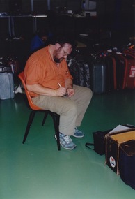
... systems used by baggage handlers in a range of airlines, worldwide. Where possible the investigation will include an epidemiological study of baggage handler back injury occurrence in those airlines. The information gathered will provide an understanding of back injury causation modes, and will focus attention on the specific tasks for which engineering solutions should be sought. Engineering solutions identified will be subject to controlled trial, to confirm their validity." This led to the construction of a full scale plywood baggage compartment model and a partnership with Ballarat University's School of Human Movement and Sports Science. Three different loading...systems used by baggage handlers in a range of airlines, worldwide. Where possible the investigation will include an epidemiological study of baggage handler back injury occurrence in those airlines. The information gathered will provide an understanding of back injury causation modes, and will focus attention on the specific tasks for which engineering solutions should be sought. Engineering solutions identified will be subject to controlled trial, to confirm their validity." This led to the construction of a full scale plywood baggage compartment model and a partnership with Ballarat University's School of Human Movement and Sports Science. Three different loading ...Victorian Institute of Occupational Safety and Health (VIOSH) Australia is the Asia-Pacific centre for teaching and research in occupational health and safety (OHS) and is known as one of Australia's leaders on the field. VIOSH has a global reputation for its innovative approach within the field of OHS management. VIOSH Australia enrolled its first PhD candidate in 1995 and during 1996 focused on attracting increasing numbers of students. In 1996, three candidates were enrolled through VIOSH Australia.They were John Culvenor, Geoffrey Dell and Thomas Mitchell. All had Prof Dennis Else as their supervisor. Previously, Geoffrey Dell was in Intake 7, 1985, Occupational Hazard Management. Geoffrey Dell's topic was "Airline Baggage Handler Back Injuries - Causes and Prevention." "The aim of this study is to investigate the work practises and operational systems used by baggage handlers in a range of airlines, worldwide. Where possible the investigation will include an epidemiological study of baggage handler back injury occurrence in those airlines. The information gathered will provide an understanding of back injury causation modes, and will focus attention on the specific tasks for which engineering solutions should be sought. Engineering solutions identified will be subject to controlled trial, to confirm their validity." This led to the construction of a full scale plywood baggage compartment model and a partnership with Ballarat University's School of Human Movement and Sports Science. Three different loading systems were tested. Qantas baggage handlers travelled to Ballarat University to fill the human frame of the investigation. The photographs show this aspect of the research. In 1997, Geoffrey Dell was awarded the Eric Wigglesworth Prize. The prize acknowledges publication of an article which constitutes a significant contribution to the body of occupational health and safety knowledge in an approved OH&S journal.32 co;our photographs showing procedure of baggage handlers.viosh, victorian institute of occupational safety and health, geoffrey dell, john culvenor, thomas mitchell, phd, airline baggage handler back injuries, work practises, operational systems, engineering solutions, causes of injury, qantas baggage handlers, prof dennis else, eric wiggles worth prize, oh&s journal, ballarate university, school of human movement and sports science, plywood compartment model, loading systems -
 Ballarat Tramway Museum
Document, Melbourne and Metropolitan Tramways Board (MMTB), "Tender Schedule for 100 Electric Trams Contract No. 3000", 1977
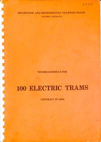
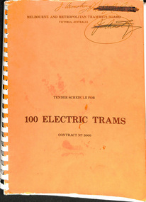
... control panels and drawings. The drawings give a map of the system, typical city route, Glenferrie Road route (grade diagram), concrete track construction, min. radius curves, loading gauge, all-electric tram and mounting details for the trolley base, schedule of prices, tender form, form of contract, and schedule of information to be provided by the tenderer. ...control panels and drawings. The drawings give a map of the system, typical city route, Glenferrie Road route (grade diagram), concrete track construction, min. radius curves, loading gauge, all-electric tram and mounting details for the trolley base, schedule of prices, tender form, form of contract, and schedule of information to be provided by the tenderer. ...Compiled and published by the Melbourne and Metropolitan Tramways Board, closing Monday 10 May 1977. Details the conditions of tender, conditions of contract, notes, specifications, gives background information about Melbourne, dimensions, performance, drivers and conductors, trucks, wheels, brakes, electrical equipment, control panels and drawings. The drawings give a map of the system, typical city route, Glenferrie Road route (grade diagram), concrete track construction, min. radius curves, loading gauge, all-electric tram and mounting details for the trolley base, schedule of prices, tender form, form of contract, and schedule of information to be provided by the tenderer. Includes an Alphabetical Index. Includes a drawing for a single-ended version of the tramcar. Became the Z3 class following the addition of a rear or 3rd door. Yields information about the 1977 tender for 100 electric tramcars that became the Melbourne Z3 class tram.Comb bound (white plastic) specification or tender document, approx 180 pages, with glossy card orange covers, titled "Tender Schedule for Electric Trams" and "Contract 3000". "1977" on front cover in ink.tramways, tramcars, z3 class, specification, tenders, mmtb, melbourne, single ended tramcars -
 Ballarat Tramway Museum
Document - Specification, Melbourne and Metropolitan Tramways Board (MMTB), "Tender Schedule for All-Electric Trams", 1972
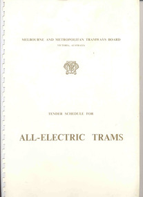
... control panels and drawings. The drawings give a map of the system, typical city route, Glenferrie Road route (grade diagram), concrete track construction, min. radius curves, loading gauge, all-electric tram and mounting details for the trolley base, schedule of prices, tender form, form of contract, schedule of information to be provided by the tenderer....control panels and drawings. The drawings give a map of the system, typical city route, Glenferrie Road route (grade diagram), concrete track construction, min. radius curves, loading gauge, all-electric tram and mounting details for the trolley base, schedule of prices, tender form, form of contract, schedule of information to be provided by the tenderer. ...Comb bound (white plastic) specification document, approx. 70 pages, with glossy card covers, titled "Tender Schedule for All-Electric Trams", published by the Melbourne and Metropolitan Tramways Board, closing 2 Oct. 1972. Details the conditions of tender, conditions of contract, notes, specification, gives background information about Melbourne, dimensions, performance, drivers and conductors, trucks, wheels, brakes, electrical equipment, control panels and drawings. The drawings give a map of the system, typical city route, Glenferrie Road route (grade diagram), concrete track construction, min. radius curves, loading gauge, all-electric tram and mounting details for the trolley base, schedule of prices, tender form, form of contract, schedule of information to be provided by the tenderer.trams, tramways, specification, tenders, z class trams, mmtb, melbourne -
 Melbourne Tram Museum
Document - Specification, Melbourne & Metropolitan Tramways Board (MMTB), "Design, Manufacture and delivery of 100 only all-electric trams", Jun. 1965
... control panels and drawings. The drawings give a map of the system, typical city route, Glenferrie Road route (grade diagram), concrete track construction, min. radius curves, loading gauge, all-electric tram and mounting details for the trolley base, schedule of prices, tender form, form of contract, schedule of information to be provided by the tenderer. ...control panels and drawings. The drawings give a map of the system, typical city route, Glenferrie Road route (grade diagram), concrete track construction, min. radius curves, loading gauge, all-electric tram and mounting details for the trolley base, schedule of prices, tender form, form of contract, schedule of information to be provided by the tenderer. ...Specification or Tender Document - titled "Design, Manufacture and delivery of 100 only all-electric trams", and "Background Information and Preliminary Specification", dated June 1965. Bound into a brown foolscap card cover. Details the conditions of tender, conditions of contract, notes, specification, gives background information about Melbourne, dimensions, performance, drivers and conductors, trucks, wheels, brakes, electrical equipment, control panels and drawings. The drawings give a map of the system, typical city route, Glenferrie Road route (grade diagram), concrete track construction, min. radius curves, loading gauge, all-electric tram and mounting details for the trolley base, schedule of prices, tender form, form of contract, schedule of information to be provided by the tenderer. Comprises: 1 - Conditions of Tendering - 1 page 2 - Conditions of Contract - 4 pages 3 - Contents - 3 pages 4 - Notes for prospective tenderers - dated June 1965 5 - General nature of contract - 21 pages 6 - Appendix A - climate data - two sheets 7 - List of 14 appended drawings 8 - O.6887A - cross section of trolley wire 9 - P.13855 - Glenferrie Road, Longitudinal Section 10 - P.13856 - Wattle Park Route 11 - P.13857 - East Preston Route 12 - P13858 - Concrete track construction 13 - P13859 - Open track construction 14 - P.13860 - Paved ballast track construction 15 - P.13887 - Tram Route - locations of substations and section switches 16 - P.13888 - Minimum radius service curves to give minimum clearance between tramcars 17 - P.13889 - Grooved Rail - 102 pounds per yard and tire profile 18 - R10-301 - Loading gauge, proposed electric tramcars 19 - R9706K - Rolling stock data, tramcars 20 - R10306 - Collins Points Shifter - Wiring diagram. 21 - Schedule of data to be supplied by the tenderer 22 - notes on Automatic Points shifters - 2 sheets 23 - Tender prices and delivery periods - 2 sheets. See Reg Item 2266 for the 1972 version and 1583 for the August 1966 version. See Reg Item 4049 for associated newspaper cuttings. See file htd4667i1.pdf for scans of the drawings.In ink in top right hand corner - "Lees"trams, tramways, specification, tenders, z class, mmtb, melbourne -
 Puffing Billy Railway
Lister Auto Truck
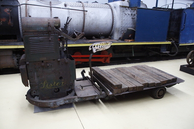
... controlled truck from behind. Under the engine cover were two equal diameter tanks, a fuel tank for petrol and a shorter oil tank. Engine and chain-drive lubrication used a total-loss oil system, controlled by a small pump and needle valve. Info Ref: Lister Auto-Truck - Wikipedia https://en.wikipedia.org/wiki/Lister_Auto-Truck Historic - Industrial monowheel tractor for moving light loads ...The Lister Auto-Truck was a small monowheel tractor built for moving light loads around factories, railway yards and similar sites. They were built by R A Lister and Company of Dursley, Gloucestershire, well known for their range of small stationary engines The Auto-Truck was one of several monowheel tractors to appear in the 1920s and '30s, with the availability of small, reliable petrol engines, as developed for motorcycles and the stationary engines for which Lister were already known. These were tricycle vehicles, with the single leading wheel used for both drive and steering. Their simple construction carried most of the mechanism on this wheel as a single unit, the chassis with the trailing wheels being little more than a trailer for balance. Simplicity was a key feature. The engines were single-cylinder and air-cooled. Ignition was by magneto, rather than requiring a battery and electrical system. One of these designs was produced in the 1920s by George Grist of the Auto Mower Co., Norton St Philip, Somerset. The engine was a JAP 600 cc four-stroke air-cooled sidevalve, a typical small engine of the time. The Auto Mower Co. were Lister agents and when Lister heard of this 'Auto-Truck' they bought one for use in their own factory. It was used to carry heavy engine castings from the foundry to the machine shop. Lister customers saw them and there was such interest in wanting to buy them that Lister negotiated with Auto Mower to build them under licence. Although Lister were already well known for their small petrol stationary engines, these were heavy cast-iron engines with water hopper cooling and unsuitable for vehicle use. Lister remained with the JAP engine for the Auto-Truck. The Auto-Truck was designed for use in factories or other places with smooth surfaces of concrete or tarmac. This allowed the use of small solid-tyred wheels with only simple suspension, making the vehicle simple, cheap and lightweight. They had little ability on soft surfaces though and could even topple over if driven carelessly across slopes. Their design was a compromise between the top-heavy nature of the tall engine grouping above its wheel and a well thought-out chassis for stability. The bearing between them was a large diameter ring roller bearing, mounted at the lowest part of the chassis. This gave rigidity and stability, even after long wear. A ring of rolled channel girder was attached to the engine group and rollers on the chassis carried the load upon this. On early Auto-Trucks this bearing is set very low, in line with the chassis members, and is covered by thin steel plates. The front panel of the engine cover is distinctive with large ventilation holes and a Lister signature cut through it. Strangely this panel is made of thick cast iron, providing substantial weight high on the engine and only adding to its top heaviness. To improve visibility of moving vehicles in noisy factories, this panel was often painted white, the rest of the vehicle being Lister's usual brunswick green. The driver was seated on a Brooks bicycle saddle, which in recognition of the lack of vehicle suspension, was carried on the end of a cantilevered bar that acted as a leaf spring. A wide handlebar on the engine group was used for steering. A squeeze bar the width of this handlebar engaged the clutch. Controls included a hand throttle, a gear lever with two forward and one reverse gears, and a large handbrake lever. The engine unit rotated freely for a full 360° rotation. When used in reverse, the Auto-Truck could either be driven from the saddle, looking backwards over the driver's shoulder; or they could dismount, swivel the engine unit around and control it as a pedestrian-controlled truck from behind. Under the engine cover were two equal diameter tanks, a fuel tank for petrol and a shorter oil tank. Engine and chain-drive lubrication used a total-loss oil system, controlled by a small pump and needle valve. Info Ref: Lister Auto-Truck - Wikipedia https://en.wikipedia.org/wiki/Lister_Auto-TruckHistoric - Industrial monowheel tractor for moving light loads around factories, railway yards and similar sites.The Lister Auto-Truck - small monowheel tractor Made of steel with three wheels. Powered by a J.A.P single cylinder petrol motor which is Hand Cranked to start.Lister puffing billy, lister, lister auto truck, monowheel tractor -
 Melbourne Tram Museum
Document - Tender Document, Melbourne & Metropolitan Tramways Board (MMTB), "Design, Manufacture and delivery of 100 only all-electric trams", Aug. 1966
... control panels and drawings. The drawings give a map of the system, typical city route, Glenferrie Road route (grade diagram), concrete track construction, min. radius curves, loading gauge, all-electric tram and mounting details for the trolley base, schedule of prices, tender form, form of contract, schedule of information to be provided by the tenderer. ...control panels and drawings. The drawings give a map of the system, typical city route, Glenferrie Road route (grade diagram), concrete track construction, min. radius curves, loading gauge, all-electric tram and mounting details for the trolley base, schedule of prices, tender form, form of contract, schedule of information to be provided by the tenderer. ...Comb bound (white plastic) specification or tender document, approx. 70 pages, with glossy card covers, titled "Tender Schedule for All-Electric Trams", published by the Melbourne and Metropolitan Tramways Board, closing 12 September 1966. Details the conditions of tender, conditions of contract, notes, specification, gives background information about Melbourne, dimensions, performance, drivers and conductors, trucks, wheels, brakes, electrical equipment, control panels and drawings. The drawings give a map of the system, typical city route, Glenferrie Road route (grade diagram), concrete track construction, min. radius curves, loading gauge, all-electric tram and mounting details for the trolley base, schedule of prices, tender form, form of contract, schedule of information to be provided by the tenderer. Second copy from same donor added 9-3-2017 See Reg Item 2266 for the 1972 version and 4667 for a draft version - dated June 1965. See Item 4388 for the Z3 document. See Reg Item 4049 for associated newspaper cuttings.In red felt pen on top right hand corner "(1966)". Has stamp "Discarded from PTC Library 22 Oct. 1989" on front cover. 2nd copy has "1966" in ink in top right hand corner.trams, tramways, specification, tenders, z class, mmtb, melbourne -
 Melbourne Tram Museum
Document - Tender Document, Melbourne & Metropolitan Tramways Board (MMTB), "Tender Schedule for All-Electric Trams - Contract 2500", Jul. 1972
... control panels and drawings. The drawings give a map of the system, typical city route, Glenferrie Road route (grade diagram), concrete track construction, min. radius curves, loading gauge, all-electric tram and mounting details for the trolley base, schedule of prices, tender form, form of contract, schedule of information to be provided by the tenderer. ...control panels and drawings. The drawings give a map of the system, typical city route, Glenferrie Road route (grade diagram), concrete track construction, min. radius curves, loading gauge, all-electric tram and mounting details for the trolley base, schedule of prices, tender form, form of contract, schedule of information to be provided by the tenderer. ...Comb bound (white plastic) specification or tender document, approx. 70 pages, with glossy card covers, titled "Tender Schedule for All-Electric Trams" and "Contract 2500", published by the Melbourne and Metropolitan Tramways Board, closing Monday 2 October 1972. Details the conditions of tender, conditions of contract, notes, specification, gives background information about Melbourne, dimensions, performance, drivers and conductors, trucks, wheels, brakes, electrical equipment, control panels and drawings. The drawings give a map of the system, typical city route, Glenferrie Road route (grade diagram), concrete track construction, min. radius curves, loading gauge, all-electric tram and mounting details for the trolley base, schedule of prices, tender form, form of contract, schedule of information to be provided by the tenderer. On the inside of the cover is a memo from D. Snell, Deputy Chairman to the Testing Engineer, dated 11/7/1972 about the tender being issued, but requesting least publicity and all enquiries to Mr. Snell. Part of the work to tender for the construction of Z class trams. Document scanned to pdf file word searchable. See Item 4388 for the Z3 document and 1583 for an August 1966 version and Reg item 4667 for a draft June 1965 version. 2nd copy added 7/8/2020 from Keith Kings papers.In in pencil in the top right hand corner of cover "1975" crossed out and "1972" written in. On first sheet in pencil, "Howard Smith" and "Laboratory 10 Feb 1975" stamped on.trams, tramways, specification, tenders, z class, mmtb, melbourne -
 Melbourne Tram Museum
Document - Tender Document, Melbourne & Metropolitan Tramways Board (MMTB), "Tender Schedule for 100 Electric Trams Contract No. 3000", Apr. 1977
... control panels and drawings. The drawings give a map of the system, typical city route, Glenferrie Road route (grade diagram), concrete track construction, min. radius curves, loading gauge, all-electric tram and mounting details for the trolley base, schedule of prices, tender form, form of contract, schedule of information to be provided by the tenderer. ...control panels and drawings. The drawings give a map of the system, typical city route, Glenferrie Road route (grade diagram), concrete track construction, min. radius curves, loading gauge, all-electric tram and mounting details for the trolley base, schedule of prices, tender form, form of contract, schedule of information to be provided by the tenderer. ...Comb bound (white plastic) specification or tender document, approx. 180 pages, with glossy card orange covers, titled "Tender Schedule for Electric Trams" and "Contract 3000". Compiled and published by the Melbourne and Metropolitan Tramways Board, closing Monday 10 May 1977. Details the conditions of tender, conditions of contract, notes, specification, gives background information about Melbourne, dimensions, performance, drivers and conductors, trucks, wheels, brakes, electrical equipment, control panels and drawings. The drawings give a map of the system, typical city route, Glenferrie Road route (grade diagram), concrete track construction, min. radius curves, loading gauge, all-electric tram and mounting details for the trolley base, schedule of prices, tender form, form of contract, schedule of information to be provided by the tenderer. Includes an Alphabetical Index. Includes a drawing for a single ended version of the tramcar. Became the Z3 class. Only the table of contents and the drawings scanned. See Reg Items 1583 and 2266 for other similar documents. See Reg Items 337 and 338 for a report on the operation of single ended tramcars 2 copies held.Has in ink written on front cover "J Armstrong" with a stamp blacked out and other copy of the same signature.trams, tramways, z3 class, specification, tenders, mmtb, melbourne, single ended tramcars -
 Moorabbin Air Museum
Manual (Item) - (SP) AAP 7211.022-016-33CL-1 Checklist Conventional Ordnance Loading Nomad Firing Control System Checks
... Moorabbin Air Museum Moorabbin Airport 12 First Street Moorabbin melbourne Manual (SP) AAP 7211.022-016-33CL-1 Checklist Conventional Ordnance Loading Nomad Firing Control System Checks ... -
 Moorabbin Air Museum
Manual (Item) - (SP) AAP 7211.001-33CL-1 Checklist Conventional Ordnance Loading Nomad Firing Control System Checks
... Moorabbin Air Museum Moorabbin Airport 12 First Street Moorabbin melbourne Manual (SP) AAP 7211.001-33CL-1 Checklist Conventional Ordnance Loading Nomad Firing Control System Checks ... -
 Moorabbin Air Museum
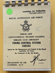
Manual (Item) - (SP) AAP 7213.001-33CL-1-1 Firing control system checks conventional weapon loading on Mirage 111-0 aircraft
... Moorabbin Air Museum Moorabbin Airport 12 First Street Moorabbin melbourne Manual (SP) AAP 7213.001-33CL-1-1 Firing control system checks conventional weapon loading on Mirage 111-0 aircraft ...