Showing 110 items matching "operating signals"
-
 National Vietnam Veterans Museum (NVVM)
Pamphlet, Australian Army, Australian Army: School of Signals: Aide Memoire: Common Operating Signals for ACP - 126 and ACP - 127 Working, 1968
... Australian Army: School of Signals: Aide Memoire: Common Operating Signals for ACP - 126 and ACP - 127 Working......Operating Signals...Australian Army: School of Signals: Aide Memoire: Common Operating Signals for ACP - 126 and ACP - 127 Working Pamphlet Australian Army ...A cream coloured cardboad pamphlet with black information of the front. This is folded like a card. Under the School of Signals insignia is the description of the phanphlet. There is the name Dawson handwritten in pencil near the top left hand corner.australian army, school of signals, aide memoire, operating signals -
 Box Hill Historical Society
Photograph - Signalman, 16/08/1958
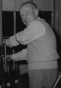
... Signalman, John Fogarty operating the signals at Box Hill railway station....Box Hill Historical Society Box Hill Heritage Centre Suite 7 Town Hall Hub Box Hill melbourne Signalman, John Fogarty operating the signals at Box Hill railway station. ...Signalman, John Fogarty operating the signals at Box Hill railway station.B&w photorailways, signalmen, fogarty> john, clothing and dress, box hill railway station -
 Sunshine and District Historical Society Incorporated
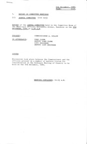
Administrative record - City of Sunshine - Commissioner Mr Alexander Alex George Gillon Collection 1976 - 1982 - Report of Committee Meetings 9th December 1980, City of Sunshine, 9th December 1980
... Closure Omar Street Telephone Box Removal Darnley Street corner Burnet Avenue Purchase ICI Oval Railway Walkover Ardeer Railway Station Condition of House 5 Hillside Crescent Maribyrnong Ernie Shepherd Gardens Keeping Chickens and Birds Parking Ballarat Road and Glencairn Avenue ICI Practice Wickets Canning Street Bridge Sunshine Football Club vandalism at Skinner Reserve Southwold Street Pre-School Centre Sunshine Park Tennis Club asphalting of two courts at Parsons Reserve Footpath Radio Street Offensive Trade Maida Avenue Pedestrian Operated Signals St. Albans Road...Albans Road Closure Omar Street Telephone Box Removal Darnley Street corner Burnet Avenue Purchase ICI Oval Railway Walkover Ardeer Railway Station Condition of House 5 Hillside Crescent Maribyrnong Ernie Shepherd Gardens Keeping Chickens and Birds Parking Ballarat Road and Glencairn Avenue ICI Practice Wickets Canning Street Bridge Sunshine Football Club vandalism at Skinner Reserve Southwold Street Pre-School Centre Sunshine Park Tennis Club asphalting of two courts at Parsons Reserve Footpath Radio Street Offensive Trade Maida Avenue Pedestrian Operated Signals St. Albans Road Foolscap sized document. ...Closure Omar Street Telephone Box Removal Darnley Street corner Burnet Avenue Purchase ICI Oval Railway Walkover Ardeer Railway Station Condition of House 5 Hillside Crescent Maribyrnong Ernie Shepherd Gardens Keeping Chickens and Birds Parking Ballarat Road and Glencairn Avenue ICI Practice Wickets Canning Street Bridge Sunshine Football Club vandalism at Skinner Reserve Southwold Street Pre-School Centre Sunshine Park Tennis Club asphalting of two courts at Parsons Reserve Footpath Radio Street Offensive Trade Maida Avenue Pedestrian Operated Signals St. Albans Roadomar street, maidstone, darnley street, burnet avenue, braybrook, ardeer railway station, ardeer, hillside crescent, maribyrnong, ernie shepherd gardens, yardley street, ballarat road, ici oval, john mcleod reserve, deer park, canning street bridge, canning street, avondale heights, sunshine football club, skinner reserve, churchill avenue, southwold street, st. albans, sunshine park tennis club, parsons reserve, stanford street, sunshine, radio street, maida avenue, sunshine north, st. albans road -
 Whitehorse Historical Society Inc.
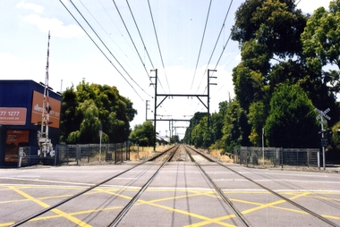
Photograph - Coloured Photograph, Blackburn Railway Road, 2012
... The station opened as ac staff and ticket station on 12/8/1889 with hand operated gates.Automatic signalling was introduced on 13/7/1958....The station opened as ac staff and ticket station on 12/8/1889 with hand operated gates.Automatic signalling was introduced on 13/7/1958. blackburn road blackburn blackburn railway crossing Coloured photograph of the Blackburn Road railway crossing at Blackburn, looking east towards Ringwood - 2012 Blackburn Railway Road Photograph Coloured Photograph ...Blackburn Railway station opened on 25/12/1882 but was not staffed and the crossing was not manned. The station opened as ac staff and ticket station on 12/8/1889 with hand operated gates.Automatic signalling was introduced on 13/7/1958.Coloured photograph of the Blackburn Road railway crossing at Blackburn, looking east towards Ringwood - 2012blackburn road, blackburn, blackburn railway crossing -
 Melbourne Tram Museum
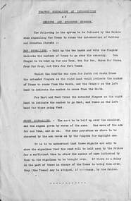
Document - Notice cable trams, Melbourne & Metropolitan Tramways Board (MMTB), "Traffic Signalling", 1921
... Details how Police would signal for the number of trams to cross in either direction and how the signalman would operate the signals and the cable depression lever for Collins St cable cars. ...Details how Police would signal for the number of trams to cross in either direction and how the signalman would operate the signals and the cable depression lever for Collins St cable cars. ...Notices to cable tram employees and signalmen about the operation of the intersection of Collins and Swanston Street c1921. Details how Police would signal for the number of trams to cross in either direction and how the signalman would operate the signals and the cable depression lever for Collins St cable cars. The Rules for signalmen dated 1/7/1921 and signed by J G Roberts, Manager Cable system for the MMTB. This intersection was one of the busiest in Melbourne running four separate routes in Collins St and the busy St Kilda Road route.Yields information about the cable tram operation of Swanston and Collins St and signalmen.Two foolscap photocopied sheets, stapled in top left hand corner.tramways, cable trams, swanston st, collins st, signalmen, police -
 Wodonga & District Historical Society Inc
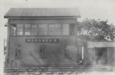
Photograph - Fred Rochow Railways Collection - Signal Box B, Wodonga Station, Before 1964
... Signal Box B was located on the south-east side of the High Street level crossing and controlled the High Street gates. A big wheel was used to operate... Box B On front of building "WODONGA B" Signal Box B was located on the south-east side of the High Street level crossing and controlled the High Street gates. A big wheel was used to operate ...The Fred Rochow Railways Collection incorporates photos related to the operation of the Wodonga Railway Station including different types of trains and railways staff C. 1930 – 1990. It was donated to the Wodonga Historical Society by Fred Rochow, a railwayman who spent many years based in Wodonga. He joined the Victorian Railways on 17th June l947 and retired in 1988. For some time, he was a member of the Australian Federated Union of Locomotive Enginemen and served a term as a member of the Trades Hall Council. He had an extensive knowledge of the struggles that took place to achieve better conditions for railway workers. Fred worked for many years as a fireman and then worked his way up the ranks to driver, experiencing many changes from the days of steam locomotives through to diesel trains, locomotives and even the modern XPT train. He worked throughout Victoria at different stages of his career, with his final working years focused on the northeast of Victoria and the Albury to Melbourne line. After his retirement, Fred continued to share his love of steam miniature trains with the community.This collection has local and statewide significance as it captures images of trains, locomotives and personnel who operated the railway services in Wodonga and throughout Northeast Victoria. The railways played a critical role in opening up Victoria and connecting Australia for trade, business, social communication and transport.Signal Box B was located on the south-east side of the High Street level crossing and controlled the High Street gates. A big wheel was used to operate the gates. The Signal Box B was demolished on May 10th, 1964, when the standard gauge line to Albury was completed. On front of building "WODONGA B"railways wodonga, fred rochow, wodonga signal box b -
 Ballarat Tramway Museum
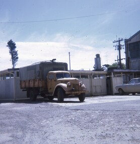
Slide - 27mm sq, Andrew Howlett, SEC Ford Welding truck Power Station yard, Dec. 1969
... Note the hand vice on the front bumper bar and the hand operated turn and stop signal device. See Reg Item 2864 for a view of this truck at work at View Point and 10003 working at the Lydiard St Level crossing....Note the hand vice on the front bumper bar and the hand operated turn and stop signal device. See Reg Item 2864 for a view of this truck at work at View Point and 10003 working at the Lydiard St Level crossing. ...Photograph developed Dec 1969 of the SEC Ford Welding truck, complete with Trolley Pole in the Power Station yard. Welder, weld. Note the hand vice on the front bumper bar and the hand operated turn and stop signal device. See Reg Item 2864 for a view of this truck at work at View Point and 10003 working at the Lydiard St Level crossing.Yields information about SEC Ballarat Welding truck fitted with a trolley pole.Colour slides, Kodak white cardboard mount.ballarat, tramways, trams, sec, trackwork, welding -
 Ballarat Tramway Museum
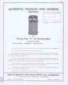
Pamphlet, The Forest City Electric Co. Limited England, "Automatic Tramway and Crossing Signals", c1948
... Level crossing signal operated by approaching cars 4. Turning Warning signals with notes on rear page of the set up for automatic control signals for rail crossings on roads, docks etc. ...Level crossing signal operated by approaching cars 4. Turning Warning signals with notes on rear page of the set up for automatic control signals for rail crossings on roads, docks etc. ...Yields information about the types of tramway signals available for use on tramways systems. The type BY was used by the SEC in Ballarat and Bendigo.Four page Pamphlet or Brochure Forest City ATS1, printed brochure with illustrations "Automatic Tramway and Crossing Signals" – four types noted. Four types: 1. Tramway type "C: Car counting signal, up to 10 cars 2. Tramway type "BY" - non car counting signals 3. Level crossing signal operated by approaching cars 4. Turning Warning signals with notes on rear page of the set up for automatic control signals for rail crossings on roads, docks etc. Date stamped by SEC 20/9/1949 on front cover.Has “218” in biro in bottom left hand corner.trams, tramways, forest city signals, level crossings, signals -
 Southern Sherbrooke Historical Society Inc.
Photograph - Photo - A truck owned by Bill Hermon is apparently being refuelled
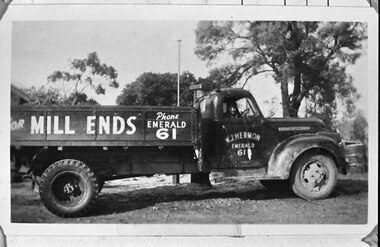
... There is a manually operated turning indicator – a large white hand shape on a pivoting rod – attached to the door. It appears that the signal is operated through the open driver's window. ...There is a manually operated turning indicator – a large white hand shape on a pivoting rod – attached to the door. It appears that the signal is operated through the open driver's window. ...B&W photo of an open tray truck parked in front of a fuel pump on rough open ground with trees in the background. There is a tall pole beside the pump. The truck has 'MILL ENDS Phone EMERALD 61' painted on the side of the tray, and 'W. J. Hermon/EMERALD/61' painted on the door. There is a manually operated turning indicator – a large white hand shape on a pivoting rod – attached to the door. It appears that the signal is operated through the open driver's window. An unidentified man is in the driver's seat and he is smiling at the camera. Dated 1948. -
 Warrnambool and District Historical Society Inc.
Document, Prospectus (Leahy’s Electrical), 1951
... operated in conjunction with Leahy’s Hire Cars and commenced in 1946. This was initially a good business with 25 employees but the building stock and plant were destroyed by fire in 1950 with the business continuing on a limited scale until the new company in 1951 was formed. Jim Leahy purchased the freehold at the corner of Liebig and Koroit Streets and the business prospered from there but today it is based back in Fairy Street This prospectus is of some significance as it signals the start of the important business in Warrnambool today of Leahy’s Electrical. ...This is the 1951 prospectus of the new company known as Leahy’s Electrical Industries Limited and formed from the previous business of Jim Leahy, Electrical Engineer. The business was then and remains today at 82 Fairy Street, Warrnambool . The business of Jim Leahy had been operated in conjunction with Leahy’s Hire Cars and commenced in 1946. This was initially a good business with 25 employees but the building stock and plant were destroyed by fire in 1950 with the business continuing on a limited scale until the new company in 1951 was formed. Jim Leahy purchased the freehold at the corner of Liebig and Koroit Streets and the business prospered from there but today it is based back in Fairy StreetThis prospectus is of some significance as it signals the start of the important business in Warrnambool today of Leahy’s Electrical. The prospectus shows that the original directors were Leahy, Dwyer, Walter, Croft, White and Affleck and they were prominent Warrnambool and district people at that time. This prospectus also has a good summary of the history of the Leahy business up to 1951 and the financial statements etc are of considerable importance to researchers and other readers. This is a typed prospectus of six pages printed back to back and with a buff-coloured cover of lightweight card. The printing on the cover is dark blue. Front Cover: ‘Prospectus of Leahy’s Electrical Industries Ltd, Warrnambool, Vic, Collett & Munday, Printers, 254 Timor Street, Warrnamboolleahy’s electrical, jim leahy, leahy's electrical prospectus, warrnambool -
 Bendigo Military Museum
Equipment - WIRELESS REMOTE CONTROL UNIT, PMG, 1944
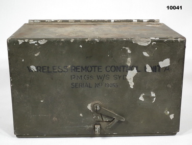
... Signals Army Equipment Remote control unit Inside on battery compartment lid is:- "Wireless Remote/ Control Unit A/ PMG W/S STD/ Ser No. 19055/ 1944” Heavy Cast aluminium box with hinged lid. Colour is drab olive. Each end has a belt loop. There is a semi rotating clip on the front of the lid section to hold it shut. Inside are, Morse key, 3 switches, Buzzer Assembly, 3 terminals and built in battery box. Inside the lid are the circuits for the device and operating ...Heavy Cast aluminium box with hinged lid. Colour is drab olive. Each end has a belt loop. There is a semi rotating clip on the front of the lid section to hold it shut. Inside are, Morse key, 3 switches, Buzzer Assembly, 3 terminals and built in battery box. Inside the lid are the circuits for the device and operating instructions. On lid top are numbers 732 and an arrow head. On front is "Wireless Remote Control Unit A, PMG s W/S SYD. Serial No. 19055." Insie the hinge bracket is broken.Inside on battery compartment lid is:- "Wireless Remote/ Control Unit A/ PMG W/S STD/ Ser No. 19055/ 1944”signals, army, equipment, remote control unit -
 Bendigo Military Museum
Equipment - WIRELESS REMOTE CONTROL UNIT, Stromberg-Carlson, 1941
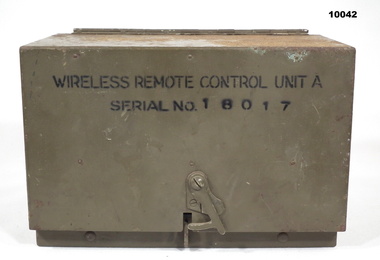
... Signals Army Morse code Inside on Battery cover is: - “Wireless Remote Control Units 'A'./ Stromberg Carlson Serial No....... 1941” Inside on front panel is :- “Serial No. 18017/ D^D Vac No. ZA 7533". Heavy cast Aluminium box with hinged lid. Colour is drab olive. Each end has a belt loop. There is a semi rotating clip on the front of the lid section to hold it shut. Inside are Morse Key, 3 switches, Buzzer Assembly, 3 terminals and a built in battery box. Inside the lid are the circuits for the device and operating ...Heavy cast Aluminium box with hinged lid. Colour is drab olive. Each end has a belt loop. There is a semi rotating clip on the front of the lid section to hold it shut. Inside are Morse Key, 3 switches, Buzzer Assembly, 3 terminals and a built in battery box. Inside the lid are the circuits for the device and operating instructions. On lid is stamped 'D^D'. On front is "Wireless Remote Control Unit A, Serial No. 18017. Inside is marked serial 18017. Inside on Battery cover is: - “Wireless Remote Control Units 'A'./ Stromberg Carlson Serial No....... 1941” Inside on front panel is :- “Serial No. 18017/ D^D Vac No. ZA 7533".wireless remote control unit, signals, army, morse code -
 Bendigo Military Museum
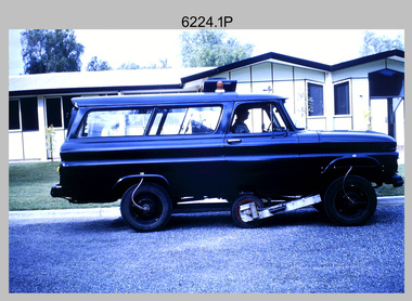
Photograph - Johnson Ground Elevation Meter (JGEM) Survey Vehicle - Army Survey Regiment, Fortuna, Bendigo, c1960s
... operating position by use of a constant pressure air cylinder. A telescopic bar, suspended between the front and rear axles, provided the reference datum for the angle measurement. The wheel provided the velocity or distance signal...operating position by use of a constant pressure air cylinder. A telescopic bar, suspended between the front and rear axles, provided the reference datum for the angle measurement. The wheel provided the velocity or distance signal ...This is a set of 16 photograph of the Royal Australian Survey Corps’ Johnson Ground Elevation Meter (JGEM) Survey Vehicle taken at the Army Survey Regiment, Fortuna, Bendigo. The JGEM vehicle was extensively used by RA Svy within Australia from the late 1960s. A limited number of Ground Elevation Meter (GEM) station wagon type vehicles were manufactured by General Motors Corporation (GMC) in the USA for the United States Geological Survey, Canada’s mapping agencies, RA Svy and National Mapping (Natmap). The GEM was a four-wheel drive, four-wheel steer vehicle. Four-wheel steering was necessary to avoid systematic errors caused by non-tracking of front and rear wheels on conventionally steered vehicles. The manufacturer substituted the rear axle with a front axle and connected them to form the four-wheel steering mechanism. The two Australian GEM vehicles, referred to as Johnson GEMs (JGEMs) were converted into right-hand drive. After delivery in 1964, acceptance Natmap and RA Svy testing and operator training was undertaken at the Army's School of Military Survey located at Balcombe, Victoria. A small fifth wheel was mounted on a cantilever arm suspension midway between the front and rear wheels on the right side of the vehicle. It was lowered to and raised from its operating position by use of a constant pressure air cylinder. A telescopic bar, suspended between the front and rear axles, provided the reference datum for the angle measurement. The wheel provided the velocity or distance signal through a pulse generator system. A sensitive pendulum mounted on this bar provided the angle measurement for each minute distance traversed. The JGEM contained electromechanical instruments used to determine relative elevations, by trigonometric principles, along a traversed path. These relative elevations were obtained through apparatus which measures the instantaneous angle of inclination of the road and the instantaneous velocity of the meter along such a path. Road routes over which the JGEM operated were planned so that each started and ended as near as practicable to an existing point of known elevation (formally referred to as a level traverse bench mark). The difference in height from the bench mark and the road surface alongside the JGEM’s fifth wheel was measured with a level and staff. Along each route, mapping control photo reference points where new elevation values were required were identified on aerial photographs. Under favourable conditions it was possible to survey as much as 160km in an ordinary working day. The first of RA Svy’s JGEM operations was undertaken in 1:250,000 scale map areas of Queensland. CPL John Hook was the JGEM’s main operator in the early 1970s undertaking operations covering 1:250,000 scale map blocks over northern Victoria and central NSW, each requiring 36 points (9 runs of photography and 4 points across. SPR Lyn Thompson and SPR Bob McDonagh teamed with CPL Hook on some of these JGEM operations. When RA Svy was integrated into the Royal Australian Engineers in 1996, the JGEM vehicle with the Survey Corps collection was donated to its museum. It is believed to be the last of the original manufactured fleet in existence. The JGEM has undergone extensive refurbishment to achieve roadworthiness and is currently housed at The Australian Army Museum of Military Engineering, Hoslworthy Barracks, NSW. It can be viewed by making an appointment with the museum’s curator.This is a set of 16 photograph of the Royal Australian Survey Corps’ Johnson Ground Elevation Meter (JGEM) Survey Vehicle taken at the Army Survey Regiment, Fortuna, Bendigo. The photographs were on 35mm slide film and were scanned at 96 dpi. They are part of the Army Survey Regiment’s Collection. .1) - Photo, colour, c1960s, Johnson Ground Elevation Meter (JGEM) Survey Vehicle .2) - Photo, colour, c1960s, JGEM instrumentation, on-board computer. .3) - Photo, colour, c1960s, JGEM instrumentation. .4) - Photo, colour, c1960s, JGEM instrumentation, on-board computer. .5) - Photo, colour, c1960s, JGEM tyre pressure controller .6) - Photo, colour, c1960s, JGEM rear doors, SGT Geoff Briggs. .7) - Photo, colour, c1960s, JGEM 5th wheel distance/angle measurement device in lowered position, SGT Geoff Briggs. .8) - Photo, colour, c1960s, JGEM 5th wheel distance/angle measurement device in lowered position. .9) & .10) - Photo, colour, c1960s, JGEM tyre pressure system, SGT Geoff Briggs. .11) - Photo, colour, c1960s, JGEM tyre pressure system. SGT Geoff Briggs. .12) - Photo, colour, c1960s, JGEM levelling scope, levelling staff, unidentified technicians. .13) & .14) - Photo, colour, c1960s, JGEM levelling scope, unidentified technician. .15) & .16) - Photo, colour, c1960s, probably survey operation adjusted height plotted on block base sheet. .1P to .16P - Some of the equipment is annotated on the frame of the 35mm slides.royal australian survey corps, rasvy, army survey regiment, army svy regt, fortuna, asr, surveying -
 Bendigo Military Museum
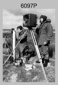
Photograph - Army Survey Regiment Personnel – Mahogany Ship Survey, Warrnambool, VIC, 1985
... To measure the distance, personnel at another site operating another MRA-301 tellurometer would have exchanged the signal emission. ...To measure the distance, personnel at another site operating another MRA-301 tellurometer would have exchanged the signal emission. ...This is a photograph of Army Survey Regiment personnel undertaking surveying measurements during a search for the ‘Mahogany Ship’ Warrnambool, VIC on 3rd September1985. CPL Mark Lander and SGT Don Williams were taking electronic distance measurements using an MRA-301 tellurometer. To measure the distance, personnel at another site operating another MRA-301 tellurometer would have exchanged the signal emission. A ‘Hilga Watts’ light appears in the background and a barometer in the foreground.This is a photograph of Army Survey Regiment personnel undertaking surveying measurements during a search for the ‘Mahogany Ship’ Warrnambool, VIC on 3rd September1985. The photograph was printed on photographic paper and is part of the Army Survey Regiment’s Collection. The photograph was scanned at 300 dpi. L to R: CPL Mark Lander, SGT Don Williams‘R.S. 3/9/1985 CPL Mark Lander, SGT Don Williams PIC BY COURTESY OF THE WARRNAMBOOL STANDARD’ annotated on back of photoroyal australian survey corps, rasvy, army survey regiment, army svy regt, fortuna, asr, surveying -
 4th/19th Prince of Wales's Light Horse Regiment Unit History Room
Book, Signal Training (All Arms) Pam No 7 Procedure for Radio Telephony 1952, July 1952
... 4th/19th Prince of Wales's Light Horse Regiment Unit History Room 4/19 PWLH Regiment, Building 78 Simpson Barracks Macleod melbourne Used by the Regiment Radio training voice procedure WO Code No 8761 Soft covered book detailing the system of calling, the procedures used for various operating conditions, and other requirements as used in radio telephony. Signal Training (All Arms) Pam No 7 Procedure for Radio Telephony 1952 Book ...Used by the RegimentSoft covered book detailing the system of calling, the procedures used for various operating conditions, and other requirements as used in radio telephony. WO Code No 8761radio training, voice procedure -
4th/19th Prince of Wales's Light Horse Regiment Unit History Room
Pamphlet, Signal Training (All Arms) Pam No 7 Procedure for Radio Telephony 1952, July 1952
... 4th/19th Prince of Wales's Light Horse Regiment Unit History Room 4/19 PWLH Regiment, Building 78 Simpson Barracks Macleod melbourne Used by the Regiment training radio procedures WO Code No 8761 Soft covered book detailing the system of calling, the procedures used for various operating conditions, and other requirements as used in radio telephony. Signal Training (All Arms) Pam No 7 Procedure for Radio Telephony 1952 Pamphlet Pamphlet ...Used by the RegimentSoft covered book detailing the system of calling, the procedures used for various operating conditions, and other requirements as used in radio telephony.WO Code No 8761training, radio procedures -
 Bendigo Military Museum
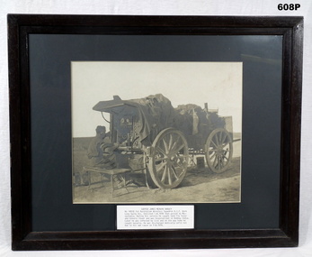
Photograph - PHOTOGRAPH, FRAMED, C. 1917 - 18
... Signal Sqd and joined the unit near Baghdad on 6.4.1918. Discharged from the AIF on 7.8.1919 as medically unfit. Wireless Sqd AIF WW1 Bottom centre: Is a bio of SAPPER JAMES MERVYN HARVEY No 14510 1st Australian Wireless Squadron AIF. Framed, black & white photo of SAPPER JAMES MERVYN HARVEY No 14510 1st Australian Wireless Squadron AIF. He is operating ...JAMES MERVYN HARVEY (telegraphist by trade) No 14510 (born Bendigo, enlisted Bendigo) in the AIF on 1.16.1916 in Australian Wireless Sqd reinforcement 3 aged 21 years 8 months. Embarked for Basra (Iraq) via Bombay 25.7.1916. It appears he was invalided to India on 12.11.1916, does not state why. He joined the Wireless Signal Service Depot in Rawalpindi India on 2.12.1917. Embarked from Bombay to Basra 27.2.1918 as part of 1st Aust & NZ Wireless Signal Sqd and joined the unit near Baghdad on 6.4.1918. Discharged from the AIF on 7.8.1919 as medically unfit.Framed, black & white photo of SAPPER JAMES MERVYN HARVEY No 14510 1st Australian Wireless Squadron AIF. He is operating a morse key mounted on the rear of a specially equipped GS wagon that is unhitched from its horses. The hatless soldier is seated on a folding bench seat & is wearing headphones. Numerous articles of personal kit are draped over the wagon. Bottom centre: Is a bio of SAPPER JAMES MERVYN HARVEY No 14510 1st Australian Wireless Squadron AIF.wireless sqd aif, ww1 -
 Doncaster RSL Sub Branch
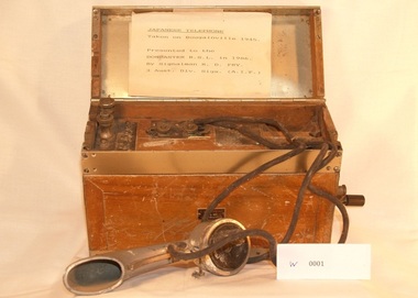
Japanese Bush telephone
... signals Communications presentered to Doncaster RSL in 1986 by signalman R D Fry 3 Aust. div. Sigs. ( A.I.F.) marked in japanese small label on front with number155420 Japanese Army bush telephone in container with manually operated generator Japanese Bush Telephone Japanese Bush telephone ...Telephone taken on Bougainville 1945 used by Japanese signals Communications presentered to Doncaster RSL in 1986 by signalman R D Fry 3 Aust. div. Sigs. ( A.I.F.)Japanese Army bush telephone in container with manually operated generatormarked in japanese small label on front with number155420 -
 The Beechworth Burke Museum
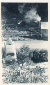
Photograph, Unknown
... operating until 1992 when it went into administration. Operations at the site were revived in 2016 and the A1 Mine is now considered one of Victoria's premier gold mines. The A1 mine is part of the extensive and prospective Lachlan Fold Belt, a north-west trending belt of tightly folded Early Devonian sedimentary rocks extending from New South Wales to Victoria. Mineralisation is hosted within or immediately adjacent to diorite dykes. Contemporary development of the 'Queens Lode' at the A1 mine signals...operating until 1992 when it went into administration. Operations at the site were revived in 2016 and the A1 Mine is now considered one of Victoria's premier gold mines. The A1 mine is part of the extensive and prospective Lachlan Fold Belt, a north-west trending belt of tightly folded Early Devonian sedimentary rocks extending from New South Wales to Victoria. Mineralisation is hosted within or immediately adjacent to diorite dykes. Contemporary development of the 'Queens Lode' at the A1 mine signals ...The A1 Gold Mine is located north of Woods Point, near Jamieson, in the Upper Goulburn region of Victoria. Gold was discovered at the A1 site in 1861 and mining operations began in 1864. The A1 Mine Settlement refers to a small township known variously as Castle Reef, Castle Point, and Raspberry Creek, which developed in the 1860s around mining industry centred on a crushing machine that worked the three gold reefs in the area. Historically, the name "A1"referred to the high quality of gold found in the quartz reefs at depths of at least two thousand feet. Along with the Morning Star mine at Woods Point, the A1 gold mine produced almost sixty percent of Victoria's gold output in the 1950s to 1970s and continued operating until 1992 when it went into administration. Operations at the site were revived in 2016 and the A1 Mine is now considered one of Victoria's premier gold mines. The A1 mine is part of the extensive and prospective Lachlan Fold Belt, a north-west trending belt of tightly folded Early Devonian sedimentary rocks extending from New South Wales to Victoria. Mineralisation is hosted within or immediately adjacent to diorite dykes. Contemporary development of the 'Queens Lode' at the A1 mine signals a move from high-grade, narrow vein airleg mining into larger scale, mechanical mining designed to increase ore production volume. This original, undated photograph of the A1 Mine appears to depict an area or phase of disuse or abandonment. The aged and humble appearance of the cottage suggests association with the historical A1 Mine Settlement, therefore the image may have been taken prior to the 1950s-1970s revival period in which the A1 mine is known to have produced high gold yields. The photograph contributes to our understanding of the A1 Gold Mine's impact on the landscape and the social, environmental impacts of mining on communities and may be compared with others in the Burke Museum's extensive collection of mining photographs to deepen our understanding of mining in the Jamieson area.Black and white rectangular photograph printed on photographic paperReverse: 5577 / A1 Mine / Near Jamieson / Vic. /burke museum, beechworth museum, beechworth, gold fields, gold rush, victorian gold rush, mining tunnels, gold ming history, colonial australia, australian gold rushes, mining technology, beechworth historic district, indigo gold trail, indigo shire, upper goulburn shire, jamieson, woods point-walhalla goldfield, a1 gold mine, victorian high country, modern mining methods, orogenic gold province, gold mineralisation, devonian, dykes -
 Running Rabbits Military Museum operated by the Upwey Belgrave RSL Sub Branch
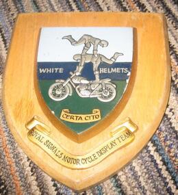
Plaque
... Running Rabbits Military Museum operated by the Upwey Belgrave RSL Sub Branch 1 Mast Gully Road Upwey melbourne Plaque current Army Royal Signals M/Cycle display team, White Helmets Plaque ...Royal Signals M/Cycle display team, White Helmetsplaque, current, army -
 Running Rabbits Military Museum operated by the Upwey Belgrave RSL Sub Branch
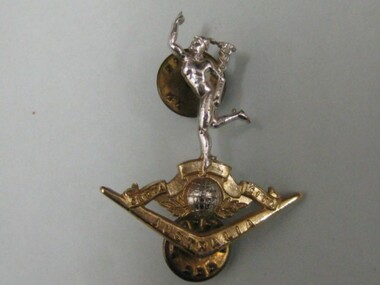
Hat Badge
... Running Rabbits Military Museum operated by the Upwey Belgrave RSL Sub Branch 1 Mast Gully Road Upwey melbourne Badge/Buttons Army Hat Badge. Signal ...Hat Badge. Signal Corpsbadge/buttons, army -
 Running Rabbits Military Museum operated by the Upwey Belgrave RSL Sub Branch
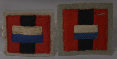
Shoulder Patch
... Running Rabbits Military Museum operated by the Upwey Belgrave RSL Sub Branch 1 Mast Gully Road Upwey melbourne Badge/Buttons Army Signals 2 Aust Army Shoulder Patch ...Signals 2 Aust Armybadge/buttons, army -
 Running Rabbits Military Museum operated by the Upwey Belgrave RSL Sub Branch
Uniform Complete
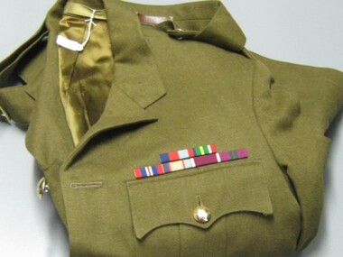
... Running Rabbits Military Museum operated by the Upwey Belgrave RSL Sub Branch 1 Mast Gully Road Upwey melbourne Uniform 1965 Army Army Jacket service dress with trousers U226 Warrant Officer. With ribbons & belt Royal Australian Corps of Signals ...Army Jacket service dress with trousers U226 Warrant Officer. With ribbons & belt Royal Australian Corps of Signalsuniform, 1965, army -
 Running Rabbits Military Museum operated by the Upwey Belgrave RSL Sub Branch
Jacket - Dress
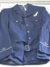
... Running Rabbits Military Museum operated by the Upwey Belgrave RSL Sub Branch 1 Mast Gully Road Upwey melbourne Uniform WW2 RAAF RAAF Signals. ...RAAF Signals. With medal ribbons in pocketuniform, ww2, raaf -
 Running Rabbits Military Museum operated by the Upwey Belgrave RSL Sub Branch
Cummerbund
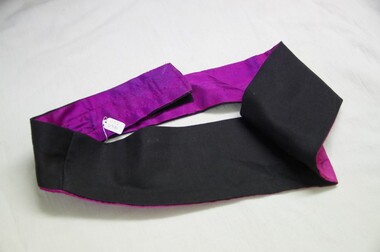
... Running Rabbits Military Museum operated by the Upwey Belgrave RSL Sub Branch 1 Mast Gully Road Upwey melbourne Uniform 1980 Army Purple Cummerbund for Signals Corps Cummerbund ...Purple Cummerbund for Signals Corpsuniform, 1980, army -
 Running Rabbits Military Museum operated by the Upwey Belgrave RSL Sub Branch
Hat - Slouch
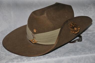
... Running Rabbits Military Museum operated by the Upwey Belgrave RSL Sub Branch 1 Mast Gully Road Upwey melbourne Headgear 1999 Army Hat, Slouch, Khaki, Felt., Signals Corps Hat - Slouch ...Hat, Slouch, Khaki, Felt., Signals Corpsheadgear, 1999, army -
 Running Rabbits Military Museum operated by the Upwey Belgrave RSL Sub Branch
Jacket - Mess
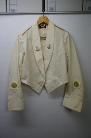
... Running Rabbits Military Museum operated by the Upwey Belgrave RSL Sub Branch 1 Mast Gully Road Upwey melbourne Uniform 1980 Army White Mess Jacket. Signals ...White Mess Jacket. Signals badges on lapels. WO1uniform, 1980, army -
 Running Rabbits Military Museum operated by the Upwey Belgrave RSL Sub Branch
Field Glasses
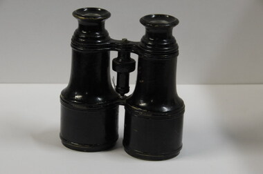
... Running Rabbits Military Museum operated by the Upwey Belgrave RSL Sub Branch 1 Mast Gully Road Upwey melbourne Equipment 1943 Found on the Kokoda Track by Lindsay (Clem) Barnes (Signals) in 1943 Field Glasses ...Found on the Kokoda Track by Lindsay (Clem) Barnes (Signals) in 1943equipment, 1943 -
 Running Rabbits Military Museum operated by the Upwey Belgrave RSL Sub Branch
Cartoon
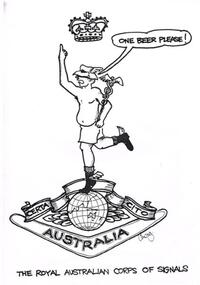
... Running Rabbits Military Museum operated by the Upwey Belgrave RSL Sub Branch 1 Mast Gully Road Upwey melbourne Picture 1970's Army Royal Australian Corps of Signals Cartoon ...Royal Australian Corps of Signalspicture, 1970's, army -
Running Rabbits Military Museum operated by the Upwey Belgrave RSL Sub Branch
Flares
... Running Rabbits Military Museum operated by the Upwey Belgrave RSL Sub Branch 1 Mast Gully Road Upwey melbourne Ammunition Vietnam Army Hand Held Signal Flare Flares ...Hand Held Signal Flareammunition, vietnam, army