Showing 41 items matching "position lines"
-
 Bendigo Historical Society Inc.
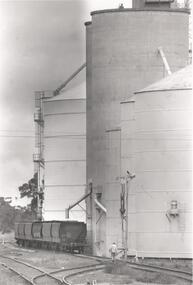
Photograph - PHOTOGRAPH. ELMORE SILOS, 1993
Photograph. Elmore silos next to railway line. Six railway trucks positioned ready to be filled. Man walking between lines toward silos and trucks.elmore, silos, agricultural -
 National Vietnam Veterans Museum (NVVM)
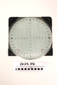
Instrument - Plotting Board, M16
Standard issue item as used by Australian servicemen during the conflict in Vietnam. A plotting board is a mechanical device used as part of a firing control system to track the observed course of a target, project its future position, and derive the azimuth (or direction) and range needed to direct the fire of the guns of a battery to hit that target.White plastic base. A circle marked with grid lines is printed on the base and a vernier for finding azimuth deflections in along top edge. Rotating disc pivots at the centre atop the disc with distances measured radially form 0 at the centre to 3400 metres around the rim range form 0-6400 metres. A scale pivoted at the centre assists in reading distances.Nth and Sth top and bottom on rotating disc. East and West in centre distances in black on outer of disc. Distances in green on inner North, South, East, West. Varn W left bottom of disc. varn E on right bottom of disc.plotting board, m16 -
 Melbourne Tram Museum
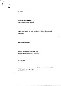
Document - Report, Public Transport Unions and Victorian Trades Hall Council, "Upgrade the Trains, Keep Sydney Road Trams - Position Paper on the Upfield Public Transport Corridor", Mar. 1989
1586 - Photocopy - report - 9 A4 sheets stapled in the top left hand corner, titled "Upgrade the Trains, Keep Sydney Road Trams - Position Paper on the Upfield Public Transport Corridor - Executive Summary", setting out the Union view of the conversion of the Upfield line to light rail. Notes the issues with the project, experience on the conversion of the St Kilda and Port Melbourne lines, level crossings and staffing. 1586.1 - as above but the full report - 66 pages, stapled along the side with clear plastic front, white card rear cover with a table of contents, including notes on the North-South rail (St Kilda and Port Melbourne) - experience to date, critique on The Met's Upfield line study, the Union's preferred option, Benefits of preferred option and the role of light rail, appendices and recommendations.trams, tramways, upfield light rail, sydney rd, unions, light rail -
 Melbourne Tram Museum
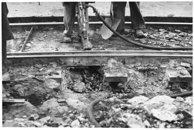
Photograph - Set of 15 Black & White Photograph/s, Melbourne & Metropolitan Tramways Board (MMTB), 1950's
Series of 15 black and white photographs of the track works to reconstruct tram lines showing various methods and works during the 1960's. .1 - Jackhammers concrete out around wooden sleepers - the rails have been bolted to them. .2 - Excavated track or temporary track next to newly relaid track - Hawthorn Road by Caulfield Park? .3 - Partly completed work - nearest track relaid, second track still has wood blocks? and then a temporary track. .4 - Excavated previously concreted and bolted track. Appears to be new rail. .5 - Compacting a new track bed with work laying track in the background. .6 - Rail being craned into position onto small concrete blocks - Nicholson St North Fitzroy at Church St - the church is now Melbourne City Mission Palliative care centre. 1955/56 - construction of the replacement track. Note the Hail bus stop sign on the corner. .7 - Thermite welding being set up. .8 - after a Thermite welding joint completed. .9 - track reading for pouting concrete, with a rebuilt track alongside and temporary track on the other side. .10 - ditto .11 - Concrete being poured .12 - ditto - could be Maribyrnong Road bridge replacement. .13 - Screeding off the concrete - possibly Nicholson St North Fitzroy .14 - completed surface - location as above .15 - completed surface with cloth covers to assist the concrete being cured. Has a MMTB hut and two worker amenity buses alongside. - location as above.Some photos have pencil marks on rear.trams, tramways, trackwork, rails, track materials, track repairs, sleepers, equipment, concrete, welding, nicholson st, new tramway, buses -
 Melbourne Tram Museum
Map, Melbourne & Metropolitan Tramways Board (MMTB), Report - "Melbourne and Metropolitan Tramways Board General Scheme", May. 1923
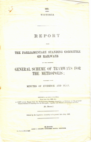
.1 - Printed document - 1923 - Report - 8 pages - The Parliamentary Standing Committee on Railways - General Scheme for Tramways for Metropolis - printed 24/7/1923. Gives details of the committee, the committee report, comments on the Board's financial position, the debate between tramways or railways, recommendations and views of the Railways Commissioners. .2 - Associated map - Map - drawing with a line back, titled "Melbourne and Metropolitan Tramways Board Proposals for General Scheme". Shows the proposed tram lines submitted to Parliament for the report into the General Scheme. Printed by Sands & McDougall Pty Ltd. Signed by J. P Strickland dated 27-8-1923. .3 - as for .1, but in good condition - added 27-3-2018 from donation of Norm Cross.trams, tramways, mmtb, general scheme, tramways, development, parliament, brighton, railways, finances, map -
 Flagstaff Hill Maritime Museum and Village
Equipment - Ship's Wheel, John Hastie et al, Early 20th Century
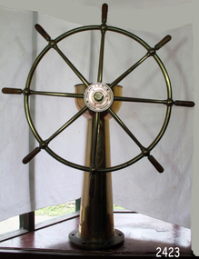
John Hastie Engineer and millwright John Hastie opened small manufacturing works in Greenock in 1845 and 1853 patented the first self-holding steering gear. The firm became known as John, Hastie and Co. Ltd. in 1898 after taking on limited liability status and their main works were at Kilblain Street, Greenock, where they specialised in ships' steering gear. The company also occupied works at Rue End Street, Greenock. Plans of this unit depict a stockyard to the east, with areas for welding; fitting and assembly; flame, cutting and fabrication; and a machine bay. The company was dissolved in 1991. Brown Brothers Brown Bros Rosebank Ironworks made the steering gears for many large ship's, including The Titanic. Andrew Betts Brown the founder was born in 1741 and closely associated with many improvements in marine engineering. He was educated in his native city and served his apprenticeship as an engineer in the locomotive works of the North British Railway Company at St. Margaret's. During his apprenticeship, he attended the evening classes at Watt College. subsequently going to Manchester to study chemistry. He went to London around 1863 and took over an old brewery, which he converted into an engineering works. During his time there he invented an overhead travelling crane, which was used on the construction of Blackfriars Bridge London. He went on to develop plant which used steam and hydraulic power for discharging ships as a result the company was contracted to install this equipment in Hamburg Docks. By around 1870 he continued to construct machinery in London but realised that conditions were more favourable in Edinburgh. He acquired land at Rosebank adjoining the North British Railway Company's line to Granton, and the necessary infrastructure was completed allowing him to finish the Hamburg contract. The works at Rosebank were eventually extended and added to until they became one of the largest engineering works in the East of Scotland. Mr Brown was a member of numerous engineering institutions, the best known at the time being the Institution of Naval Architects. He was also a Fellow of the Royal Society of Edinburgh, a member of the Institute of Mechanical Engineers and of the Institution of Marine Engineers he died in 1906 at the age of 67.An item made by two marine innovators of marine auxiliary machinery, equipment and itemsShip's wheel, brass, attached to brass pillar. The base has six holes in it for securing it in place. Top of the ship's wheel pillar has a brass, adjustable arrow pointer that is positioned over a dial etched into the flat brass surface. The dial reads " PORT STABD". Lines and degrees are marked, with '0' in centre and every 5 degrees, from 0-35, in both Port and Starboard sidesInscription to wheel hub "Brown Brothers & Co. Ltd, Rosebank Ironworks, Edinburgh"flagstaff hill, warrnambool, shipwrecked-coast, flagstaff-hill, flagstaff-hill-maritime-museum, maritime-museum, shipwreck-coast, flagstaff-hill-maritime-village, john hastie, john hastie, andrew betts brown, ships wheel, ship steering gear, marine equipment, instrument, navigation -
 Melbourne Tram Museum
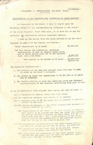
Document - Report, Melbourne & Metropolitan Tramways Board (MMTB), "Construction of new tramways and conversion of cable tramways", 8/05/1922
Report titled "Construction of new tramways and conversion of cable tramways" looking at the financial position of the board and the implications of the conversion of cable tramways and construction of new tramways. Signed by W. O Strangward 8/5/1922. Includes analysis of financing the works, the MMTB's ability top meet operating costs and statutory appropriations, loan repayments, construction of new tramcars, over crowding, reserve funds and alternative methods of undertaking the work and meeting the costs of the work. Refers to the Engineers report.Yields information about the MMTB's consideration of the conversion of the cable trams and building new lines in 1922.Report - six foolscap sheets pinned in the top left hand corner, marked confidential, stencil duplicated.trams, tramways, conversion, mmtb, cable trams, finances, new tramway, track construction -
 Vision Australia
Equipment - Object, Two line Braille frame
Designed to create an impression on paper, the slate allows users to create Braille by guiding the stylus into the correct alignment to produce Braille, through the applied use of pressure that creates a depression on one size of the paper and a raised dot on the alternative side. In this example, the frame has two side hinges which allow it to sit over the paper edge, and four lines of Braille could be written.1 metal Braille frame with two lines of Braille windows and 4 small prongs to keep frame positioned correctly.braille equipment, assistive devices -
 Bendigo Historical Society Inc.
Document - NEW CHUM & VICTORIA LINES OF REEF - NOTES ON VICTORIA HILL FOR TOURIST ATTRACTION
Handwritten notes outlining a plan for Victoria Hill, Central Nell Gwynne and New Chum Hill to be the focal position for a tourist attraction. Outlines steps to be taken to do the work and a mining museum at the Central Nell Gwynne. On the back of the page is a sketch of Victoria & New Chum Hills. On the plan is the Battery, Rae, Rae's House, Rae's Open Cut, Wittscheibe, Midway, Victoria Quartz, Lansell's 180 Shaft and the Recreation Reserve.document, gold, new chum & victoria lines of reef, central nell gwynne, new chum hill, bendigo and district tourist development association, victoria hill, lansell's big 180, victoria quartz, rae's open cut -
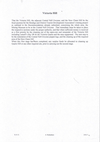
 Glenelg Shire Council Cultural Collection
Print, Carmel Wallace, Aboriginal Woman, 1983-1984
CEMA Art Collection. Part of "A Community View" 150 years in Portland Screenprint Exhibition. Part of Angela Gee Residency 1983 and 1984.Laminated screenprint of an Aboriginal woman with a white and orange background. The Aboriginal woman appears to be seated and is wearing a full-length dress. She is positioned on the lower left side of the work and portrayed in orange and black. Behind her the background has been left blank. The top and right side of the work has an orange background with white wavy lines.Front: (no inscriptions) Back: 47glenelg shire council cultural collection, portland, 150th anniversary, female artist, female artists, women, gunditjmara -
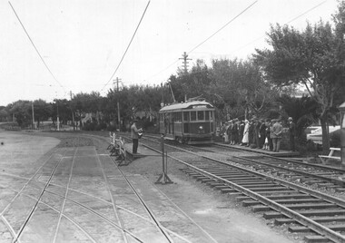 Melbourne Tram Museum
Photograph - Domain Road - cable tram conversion, C J Frazer, late Dec. 1925
... for Domain Road after the closure of the cable tram lines in St Kilda... for Domain Road after the closure of the cable tram lines in St Kilda ...The photo shows the intersection of Domain Road and St Kilda Road with W class tram 375 (Melbourne) at the tram stop for Domain Road after the closure of the cable tram lines in St Kilda Road, with installation of temporary tracks on the western side of St Kilda Road. Temporary platforms have been installed. Many passengers are waiting at the stop. The former cable tram lines are in position though some of the outbound cable tram track in St Kilda Road has been removed. There is a conductor on the outbound or southbound platform. Photo taken soon after the closure of the cable tram service on 26-12-1925, with service starting on the temporary tracks on 27-12-1925.Yields information about the conversion of St Kilda Road to electric trams from cable trams.Black and white photograph with photographer's stamp on the rear.Has the stamp of C J Fraser's on the rear with address.tramways, cable conversion, st kilda road, new tramways, domain road, tram 375