Showing 96 items
matching control panel
-
 Port Melbourne Historical & Preservation Society
Document - Reports, Department of Infrastructure to panel reviewing C5 amendment to Port Phillip Planning Scheme, Graham Deacons et al, 1999
The C5 Amendment aimed to create a framework for built form and development controls in the Port Melbourne Mixed Use Area undergoing conversion to residential development. Heritage overlays to protect heritage areas were also under review.Developer submissions to an independent Panel reviewing the C5 amendment to the Port Phillip Planning Scheme, 1999 Report from Deacons, Graham and James for Bectontown planning, built environment - civic, heritage, becton, fox hay timber and hardware pty ltd -
Port Melbourne Historical & Preservation Society
Document - Reports, Deacons, Graham and James for Becton and others to panel reviewing C5 amendment to Port Phillip Planning Scheme, Graham Deacons et al, 1999
The C5 Amendment aimed to create a framework for built form and development controls in the Port Melbourne Mixed Use Area undergoing conversion to residential development. Heritage overlays to protect heritage areas were also under review.Developer submissions to an independent Panel reviewing the C5 amendment to the Port Phillip Planning Scheme, 1999 Report from Deacons, Graham and James for Becton and otherstown planning, built environment - civic, heritage, becton, fox hay timber and hardware pty ltd -
Port Melbourne Historical & Preservation Society
Document - Reports, Deacons, Graham and James for Fox Hay and Co to panel reviewing C5 amendment to Port Phillip Planning Scheme, Graham Deacons et al, 1999
The C5 Amendment aimed to create a framework for built form and development controls in the Port Melbourne Mixed Use Area undergoing conversion to residential development. Heritage overlays to protect heritage areas were also under review.Developer submissions to an independent Panel reviewing the C5 amendment to the Port Phillip Planning Scheme, 1999 Report from Deacons, Graham and James for Fox Hay and Cotown planning, built environment - civic, heritage, becton, fox hay timber and hardware pty ltd -
Port Melbourne Historical & Preservation Society
Document - Reports, Contour Consultants to panel reviewing C5 amendment to Port Phillip Planning Scheme, Contour Consultants, 1999
The C5 Amendment aimed to create a framework for built form and development controls in the Port Melbourne Mixed Use Area undergoing conversion to residential development. Heritage overlays to protect heritage areas were also under review.Developer submissions to an independent Panel reviewing the C5 amendment to the Port Phillip Planning Scheme, 1999 Report from Contour Consultants re. 15 Beach Sttown planning, built environment - civic, heritage, becton, fox hay timber and hardware pty ltd -
Port Melbourne Historical & Preservation Society
Document - Reports, Fisher Stewart for Philco Australia to panel reviewing C5 amendment to Port Phillip Planning Scheme, Fisher Stewart for Philco Australia, 1999
The C5 Amendment aimed to create a framework for built form and development controls in the Port Melbourne Mixed Use Area undergoing conversion to residential development. Heritage overlays to protect heritage areas were also under review.Developer submissions to an independent Panel reviewing the C5 amendment to the Port Phillip Planning Scheme, 1999 Fisher Stewart for Philco Australia re. Johnsons Distillery sitetown planning, built environment - civic, heritage, becton, fox hay timber and hardware pty ltd -
 Coal Creek Community Park & Museum
Bottle, glass, c. 1934- 1978
TROVE : The Argus (Melbourne, Vic. : 1848 - 1957) Saturday 17 November 1877 p 11 Advertising PATENT ZELTZOGENE CHARGES, D. FEVRE. In boxes of ten charges, price 6s. per box. Wholesale agents, Rocke, Tompsitt, and Co., 3 Flinders street east. TROVE : ''Rocke Tompsitt Pharmaceutical wholesaler Rocke Tompsitt and Co Ltd has returned to the profit list after recording a $20,381 loss during 1976-77. However, annual dividend has been reduced from 3.5c last year to 2.5c. The group announced yesterday an after-tax profit of $312,000 after sales of $27.09 million, up 26.8 per cent. Directors said the improvement in the profit had come from the return to profitability by the Victorian wholesaling company, and the inclusion of the profit from the T. G. Cullum group for a full 12-month period. They said the company's other subsidiaries had continued to trade profitably. The group had continued to operate profitably despite excessive government price control over drugs in pharmaceutical-benefit scheme. However, the directors were optimistic that a satisfactory result would be achieved in the present year.Hexagonal in section, clear amber glass bottle with black bakelite screw top and white paper label with red text on one side. Half full with original contents. Embossed text between two panels of 'x' stipple pattern, numeral on plain side near base, numerals monogram, and letters embossed on base. Paper label in red printed text 'SOL. MERCUROCHROME', 'POISONOUS', 'NOT TO BE TAKEN'. 'Rocke, Tompsitt & Co. Pty. Ltd., Flinders-st., Melbourne'. On side of bottle between two panels of 'x' stipple pattern the embossed text 'NOT TO BE TAKEN'. On plain side near base of bottle, '2'. On base of bottle '338' over AGM monogram, with 'M' to one side, over 'F1071'.rocke, tompsitt, mercurochrome, poison, amber glass, bakelite, pharmacy -
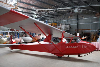 Australian Gliding Museum
Machine - Glider – Sailplane, 29/071956
The Slingsby T31 is a two seat training glider that came available in 1951. It is, in effect, a two seat version of the single seat Kirby Tutor. The T31 was marketed by Slingsby Sailplanes both as complete aircraft and kits of parts for assembly. The Australian Gliding Museum’s example (currently registered as VH-GDB) is one of five of this type to grace Australian skies. Three including GDB were assembled in Australia from kits supplied by Slingsby’s in England, the other two were delivered as completed airframes. To date only four remain of which two are airworthy. This aircraft began flying in at Caversham in Western Australia (the then home of the Gliding Club of Western Australia) in July 1956. It was badly damaged in a crash in June 1958. The wreckage was sent to Schneiders in Adelaide for repair. However, the Club decided against having the repairs done, opting instead to buy a new ES52 Kookaburra. After a couple of years, the wreck was purchased by a member of the Waikerie Gliding Club whereupon the glider was rebuilt with some modifications, including a more rounded and better streamlined fuselage nose. It returned to the air in October 1961 at Clare in South Australia. The ownership of VH-GDB passed through a number of clubs, including at Dubbo in New South Wales, Wimmera in Victoria and Pioneer Valley at Mackay in Queensland. Eventually, it came into the hands of Bill Riley of Tocumwal in New South Wales who held it in storage for many years. Riley donated the aircraft to the Museum. It has been restored to airworthiness and is flown at vintage glider rallies and on Museum open days. This exhibit is an excellent example of a Slingsby T31 Tandem Tutor, a type of glider that was used by a number of clubs in the 1950s and 1960s for dual training of pilots to the solo capability.The Slingsby T31b Tandem Tutor is an open cockpit, tandem, two-seater glider with high, pylon mounted two piece wing supported by double, wire braced, steel tube struts. The glider is fitted with a main wheel, rubber-block sprung, wooden nose skid and steel leaf sprung, brass shod tailskid. The basic controls of aileron, rudder and elevator are not supplemented with pitch trim. Wing lift spoilers and both aerotow and winch releases are fitted. The instrument panels in both cockpits are fitted with an airspeed indicator, cosim variometer and altimeter. This red and silver painted wood and fabric covered aircraft is in excellent condition having been restored to full airworthy status by the Australian Gliding Museum. SLINGSBY – T31b (nose – both sides) DB Australian Gliding Museum (rudder – both sides) It has been given Serial Number GFA/HB/12 and is registered as VH-GDBaustralian gliding, glider, sailplane, slingsby, tandem tutor, t31, gliding club of western australia, waikerie gliding club, wimmera soaring club, pioneer valley soaring club -
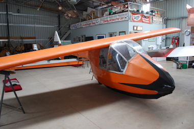 Australian Gliding Museum
Machine - Glider – Sailplane, Construction completed 1952
This unique aircraft was conceived in 1943 as a two seat trainer. A very large part of the design work can be attributed to Jock Barratt and Harold Bradley. The general layout adopted is similar to the Kite I and Kite II single seat sailplanes of Martin Warner and Allan Campbell. Having regard to this heritage, the glider was originally named Kite III but renamed Pelican 2, perhaps because it was the second two seat training glider built by the Waikerie Gliding Club – the first being the Pelican, a reconfigured Pratt Utility glider. Pelican 2 was first flown in 1952 and regularly since then, at least until about 1992. The Pelican 2’s performance was found to be very good for sailplanes of its era and was often used for more advanced flying in addition to training new pilots. Very few changes have been made to the Pelican 2 over the years. The undercarriage was modified after its initial testing to improve the placement of the wheels. The trailing edge of the rudder (originally straight) was rounded adding to the surface area. The twin shoulder tow line bridles were replaced with a belly hook when aviation design rules declared shoulder bridles dangerous and a nose hook has since been added to allow for aero-towing. A unique home grown sailplane design associated with Australian gliding pioneers Wooden 2 seat glider sailplane with fabric covering. Distinctive features include the pod and boom fuselage with side by side seating for pilot and a second person. The canopy of perspex supported by aluminum framing opens with port and starboard segments separately folding upwards and forward. The instrument panel includes altimeter, airspeed indicator, slip indicator and variometers. In addition to the usual controls, there is a trim operated by a small wheel mounted centrally, at head height, on the bulkhead at the rear of the cockpit. Incorporated in the skid under the fuselage pod are two wheels (one approximately midships and the other at the rear end). It has a three piece cantilever wing of approximately nearly 17 metres. The ailerons run almost full length of the outer wing segments. A Gottingen 426 section has been used changing to M6 at the tips. Outer wing segments are joined to the centre section to give about 300 mm of dihedral at the tips. The glider is equipped with airbrakes. The colour scheme consists of orange fuselage with black nose and skid. The tailplane / elevator and rudder are painted white. The wing is predominantly white with an orange leading edge. Registration VH-GFY On each side of rudder – “Pelican II” in black lettering on a rectangle of silver On each side of fuselage pod the letters ‘FY’ On each side of the fuselage, below the edge of the cockpit opening – “WAIKERIE” in black paint. australian gliding, glider, sailplane, kite, pelican, waikerie gliding club, jock barratt, harold bradley, martin warner, allan campbell -
Moorabbin Air Museum
Manual (item) - GAF Nomad Model 22 Maintenance Manual, Nomad 22 Series Option R632 Control Panels July 1989
... Moorabbin melbourne GAF Nomad Nomad 22 Series Option R632 Control ...GAF Nomad -
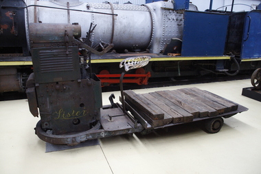 Puffing Billy Railway
Lister Auto Truck
The Lister Auto-Truck was a small monowheel tractor built for moving light loads around factories, railway yards and similar sites. They were built by R A Lister and Company of Dursley, Gloucestershire, well known for their range of small stationary engines The Auto-Truck was one of several monowheel tractors to appear in the 1920s and '30s, with the availability of small, reliable petrol engines, as developed for motorcycles and the stationary engines for which Lister were already known. These were tricycle vehicles, with the single leading wheel used for both drive and steering. Their simple construction carried most of the mechanism on this wheel as a single unit, the chassis with the trailing wheels being little more than a trailer for balance. Simplicity was a key feature. The engines were single-cylinder and air-cooled. Ignition was by magneto, rather than requiring a battery and electrical system. One of these designs was produced in the 1920s by George Grist of the Auto Mower Co., Norton St Philip, Somerset. The engine was a JAP 600 cc four-stroke air-cooled sidevalve, a typical small engine of the time. The Auto Mower Co. were Lister agents and when Lister heard of this 'Auto-Truck' they bought one for use in their own factory. It was used to carry heavy engine castings from the foundry to the machine shop. Lister customers saw them and there was such interest in wanting to buy them that Lister negotiated with Auto Mower to build them under licence. Although Lister were already well known for their small petrol stationary engines, these were heavy cast-iron engines with water hopper cooling and unsuitable for vehicle use. Lister remained with the JAP engine for the Auto-Truck. The Auto-Truck was designed for use in factories or other places with smooth surfaces of concrete or tarmac. This allowed the use of small solid-tyred wheels with only simple suspension, making the vehicle simple, cheap and lightweight. They had little ability on soft surfaces though and could even topple over if driven carelessly across slopes. Their design was a compromise between the top-heavy nature of the tall engine grouping above its wheel and a well thought-out chassis for stability. The bearing between them was a large diameter ring roller bearing, mounted at the lowest part of the chassis. This gave rigidity and stability, even after long wear. A ring of rolled channel girder was attached to the engine group and rollers on the chassis carried the load upon this. On early Auto-Trucks this bearing is set very low, in line with the chassis members, and is covered by thin steel plates. The front panel of the engine cover is distinctive with large ventilation holes and a Lister signature cut through it. Strangely this panel is made of thick cast iron, providing substantial weight high on the engine and only adding to its top heaviness. To improve visibility of moving vehicles in noisy factories, this panel was often painted white, the rest of the vehicle being Lister's usual brunswick green. The driver was seated on a Brooks bicycle saddle, which in recognition of the lack of vehicle suspension, was carried on the end of a cantilevered bar that acted as a leaf spring. A wide handlebar on the engine group was used for steering. A squeeze bar the width of this handlebar engaged the clutch. Controls included a hand throttle, a gear lever with two forward and one reverse gears, and a large handbrake lever. The engine unit rotated freely for a full 360° rotation. When used in reverse, the Auto-Truck could either be driven from the saddle, looking backwards over the driver's shoulder; or they could dismount, swivel the engine unit around and control it as a pedestrian-controlled truck from behind. Under the engine cover were two equal diameter tanks, a fuel tank for petrol and a shorter oil tank. Engine and chain-drive lubrication used a total-loss oil system, controlled by a small pump and needle valve. Info Ref: Lister Auto-Truck - Wikipedia https://en.wikipedia.org/wiki/Lister_Auto-TruckHistoric - Industrial monowheel tractor for moving light loads around factories, railway yards and similar sites.The Lister Auto-Truck - small monowheel tractor Made of steel with three wheels. Powered by a J.A.P single cylinder petrol motor which is Hand Cranked to start.Lister puffing billy, lister, lister auto truck, monowheel tractor -
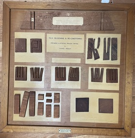 Creswick Campus Historical Collection - University of Melbourne
Mixed media - Moisture control samples board, Kiln Seasoning & Reconditioning: specimens illustrating process control and finished product
Specimens illlustrating process control & finished product.Timber demonstration wall panelMunitions Supply Laboratories. Munitions Supply Board. Department of Defence -
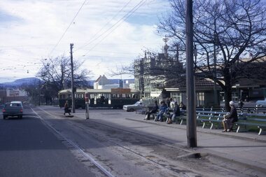
 Ballarat Tramway Museum
Slide - 35mm slide/s, Travis Jeffrey, 1961- 64
Agfa plastic mount (blue base, white cover) of a photograph of No. 27 turning from Sturt St into Drummond St Nth Tram has been fitted with dash canopy lights and tiger strips. Tram has destination of Haddon St, has a "Cook with Electricity" roof advertisement and an advertisements for White Horse Whiskey and The Age on the front dash panel. Photo taken between 1961 and 1964. Note the SEC electrical section control box on the corner by No. 27. Has Southern Cross Hotel and Rimmington Bros. Butchers in the background. Slide rescanned at 3200 dpi 24-10-2020, jpg replaced, tiff file retained. This file was scanned in 2003 and may show colour changes. "BAS 21" in penciltramways, trams, hospital corner, sturt st, drummond st, tram 27 -
 Ballarat Tramway Museum
Slide - 35mm slide/s, Travis Jeffrey, c1962
Agfa plastic mount (blue base, white cover) of a photograph of No. 20 southbound in Drummond St. South with destination of Sebastopol. Photo taken late 1960's. Has "Twin Lakes" advertisement on the front panel and the SEC roof advertisement, "Everything's under control in my all electric kitchen". Slide rescanned at 3200 dpi 25-10-2020, jpg replaced, tiff file retained. This file was scanned in 2003 and may show colour changes."BAS 38" in penciltramways, trams, drummond st. sth, tram 20 -
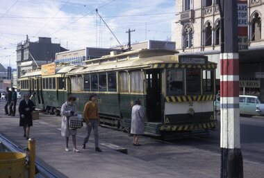
 Ballarat Tramway Museum
Slide - 35mm slide/s, Peter Moses, Aug. 1971
Photo of SEC Ballarat Tram No. 37 east bound at Lyons St. on a charter with the St. Andrews Kirk (church) in the background, on the corners of Sturt, Dawson and Lyons Streets. Photo taken after the tram has passed the photographer. Tram has "Everything's under control in my all electric kitchen" SEC roof advertisement panel. Kodak cardboard mount slide, taken by Peter Moses August 1971.On back of slide in red ink "N37 / Child ? new? Special Tram, Sturt St." and in top right hand corner in black ink "P. Moses".tramways, trams, lyons st, sturt st, st andrews kirk, tram 37 -
 Ballarat Tramway Museum
Slide - 35mm slide/s, Peter Moses, Aug. 1971
Colour slide - Photo of SEC Ballarat Tram No. 35 crossing Sturt St. from Lydiard St. North. Photo taken from the north side of Sturt St. Photo shows the tram stop arrangements for east bound trams in Sturt St. with passengers waiting on the seats. Tram has "Everything's under control in my all electric kitchen" SEC roof advertisement panel. Kodak cardboard mount slide, taken by Peter Moses August 1971.On back of slide in red ink "Ballarat / into Sturt St from Lydiard St." and in top left hand corner in black ink "P. Moses".tramways, trams, sturt st, lydiard st north, tram stops, tram 35 -
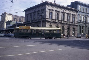
 Ballarat Tramway Museum
Slide - 35mm slide/s, Peter Moses, Aug. 1971
Colour slide - Photo of SEC Ballarat Trams No. 32 and 35 at the Sturt St. south side "City" terminus. No. 32 has destination of "Gardens via Drummond Nth" and No. 35 has "Everything's under control in my all electric kitchen" SEC roof advertisement panel. Photo shows passengers boarding tram and stop signage arrangements. Has buildings on the south side of Sturt and Lydiard in the background. Kodak cardboard mount slide, taken by Peter Moses August 1971. Image btm2047ia - cleaned up by Peter Waugh 9/2021.On back of slide in blue ink "N32 Ballarat Sturt St. terminus." and in bottom left hand corner in black ink "P. Moses".tramways, trams, sturt st, lydiard st north, tram stops, tram 35, tram 32 -
 Ballarat Tramway Museum
Slide - 35mm slide/s, Peter Moses, Aug. 1971
Photo of SEC Ballarat Tram No. 35 leaving the Sturt St. south side "City" terminus. No. 35 has "Everything's under control in my all electric kitchen" SEC roof advertisement panel. Tram has destination of "Sebastopol". Photo has building on the south side of Sturt St., including the Town Hall in the background. Kodak sign on the shop next door to the Town Hall. Kodak cardboard mount slide, taken by Peter Moses August 1971.On back of slide in blue ink "N35 / Ballarat / Sturt St. terminus" and in bottom right hand corner in black ink "P. Moses".tramways, trams, sturt st, town hall, tram 35 -
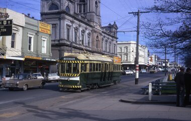
 Ballarat Tramway Museum
Slide - 35mm slide/s, Peter Moses, Aug. 1971
Photo of SEC Ballarat Tram No. 43 turning from Sturt St. into Lydiard St North with the ANZ Bank building in the background. No. 43 has "Everything's under control in my all electric kitchen" SEC roof advertisement panel. Also in the background is the SEC offices building. Photo shows the Brill 22E trucks turning or curving around the curve. Kodak cardboard mount slide, taken by Peter Moses August 1971.On back of slide in red ink "N43 Ballarat / Turning into Lydiard St." and in bottom right hand corner in black ink "P. Moses" on the reverse side of slidetramways, trams, sturt st, lydiard st, anz, tram 43 -
 Ballarat Tramway Museum
Slide - 35mm slide/s, Peter Moses, Aug. 1971
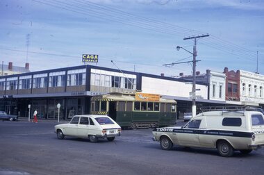
Photo of SEC Ballarat Tram No. 17 east bound in Sturt St, after crossing Doveton St. In the photograph are the buildings on the north side of Sturt St., including the CBC Bank building with a CAGA Finance sign on the top of the building . No. 17 has "Everything's under control in my all electric kitchen" SEC roof advertisement panel. Kodak cardboard mount slide, taken by Peter Moses August 1971.On back of slide in light black ink "N17 Ballarat / Sturt St. " and in bottom left hand corner in black ink "P. Moses".tramways, trams, sturt st, doveton st, cbc bank, tram 17 -
Moorabbin Air Museum
Manual (Item) - Eclipse Service Manual No.72 Generator Control Panels
... Panels Manual Eclipse Service Manual No.72 Generator Control ... -
Moorabbin Air Museum
Manual (Item) - Teledyne Controls Overhaul Manual for EFDARS Flight Data Entry Panel Part No 2223804
-
 Ballarat Tramway Museum
Slide - 35mm slide/s - set of 5, Dave Simpson, late 1960's early 1970's
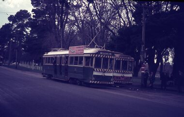
Set of five 35mm slides - Anscochrome white plastic mounts of tram 39 running a special (39), crossing other trams at Gardens Loop. .1 - 39 and 13 .2 - 39 and 26 .3 - 39 .4 - 39 .5 - 39 Tram 39 has a SEC - all under control in my all electric kitchen roof advertisement, 26 a Briquettes roof advert and 13 a Twin Lakes dash panel advert.tramways, trams, gardens loop, wendouree parade, special trams, tram 13, tram 26, tram 39 -
 Maldon Vintage Machinery Museum Inc
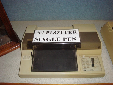
Digital Plotter, Estimated 1980's
Early model A4 single pen computer controlled digital plotter. Cream coloured plastic outer case with clear tinted hinged plastic cover over pen compartment. On the back panel various inscription panels indicating it is a Hewlett Packard machine Model 7470A Serial No. 2210A 12562.drafting, computers, digital -
 Maldon Vintage Machinery Museum Inc
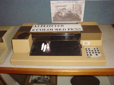
Digital Plotter, Estimated 1980's
Computer controlled digital plotter, A3 paper size with 6 pens of various colours. Beige plastic case with clear tinted hinged cover over pen compartment.Makers name "digital" on front panel. Stick on label on back panel with cautions and warnings. Also Model LVP16, SN: HY 01106.computers, drafting, digital -
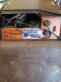 Vision Australia
Equipment - Object, Telesensory Systems, Optacon, 1974
The Optacon OPtical-to-TActile-CONverter is a compact, portable reading aid for the blind. It is about the size of a textbook, and weighs less than 2kg. It works by converting a printed image into a tactile image that a blind person can feel with one finger. After a period of training and practice, a blind person can use the Optacon to read ordinary books, magazines, newspapers, and other printed materials. The Optacon was developed after intensive research at Standford University, California, USA and was trialed by clients of the Royal Victorian Institute for the Blind (now part of Vision Australia) in 1973. It has three main sections: 1 a miniature camera, 2 an electronics section, and 3 a tactile stimulator array. The miniature camera, about the size of a pocket knife, is mounted in a housing that has rollers for easy movement along a line of print. The camera is connected to the electronics section by a lightweight cable. The electronics section and the tactile stimulator array are in the main chassis. The array consists of 144 tiny metal rods arranged in six vertical columns and 24 horizontal rows. Each of the rods can vibrate independently. The tips of these rods protrude through holes in a concave finger plate where the index finger is placed flat in order to read. These three components act together to convert the image of a printed letter or other shape into a pattern of vibrating rods, a tactile image of the letter or shape. The letter shape is tactually perceived as an image that moves from right to left on the finger, showing the left or leading edge of the letter first. Letters are felt sequentially rather than all at once, and the image should be kept moving. The Optacon converts a printed O into a tactile form that resembles a crater with a vibrating rim -- a completed circle. C would have a gap or opening on the right side of the curve. The letter F would be felt, sequentially, as a vertical line with two trailing horizontal lines. Because it can convert any ordinary printed image into a corresponding tactile image, the Optacon is not restricted to any special typestyle or language. The camera has a zoom lens that compensates for differences in the size of type. The standard Optacon lens can accommodate type sizes from 6 point to 20 point. With the optional F4A magnifier lens, type sizes as small as 4 point can be read. Powered by a rechargeable battery, and comes with its own battery charger. The battery is contained within the main chassis, and is not removable by the user. There are four basic controls on the Optacon: the Magnification Adjustment zoom button located on the camera section on the side opposite the rollers; and the On-Off switch, the Stimulator Intensity Adjustment knob, and the Threshold Adjustment knob located on the right side of the front panel. The Circuit Breaker protrudes from the right-hand wall inside the chassis compartment. From left to right when the back panel is facing you, are located: the jack for connecting the battery charger; the Battery Check button; the Normal-Invert switch; and the Input/Output I/O connector for use with the Visual Display, when using the Repeater Cable to connect two Optacons to one another or with other accessories. Designed not be removed from the leather case during normal operation, the On-Off switch is a slide switch located on the right side of the front panel. It slides up and snaps into place in the on position. 1 black with orange front, rectangular device in leather case assistive devices, audio equipment -
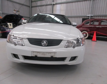 Trafalgar Holden Museum
Vehicle - VY Acclaim sedan, 2002
The front and rear of the body had minor restyling, with new front grille, headlights and taillights. The interior has been significantly upgraded. Interior upgrade includes a new instrument panel, centre console and steering wheel and new design transmission lever and handbrake.[2] There is also a new mobile phone power outlet under the centre console. The new instrument cluster features a large multi-function digital display (single or triple-window, depending on model), which displays information such as radio station display, PRND321 gear selected indicator, trip computer with stopwatch function, service reminders and a help facility. Standard features (on some models) now include "twilight sentinel" - automatic headlamp control, programmable headlamps off time delay, high feature Blaupunkt audio systems, road-speed sensitive intermittent wipers and passenger airbags. The VY Series II update added cruise control, front power windows variable front seat lumbar support, and revised interior trims. A 245 kW (329 hp) V8 was introduced to sports variants and a sportier repositioning of the Calais model. This repositioning included a subtle body kit, the option of a 235 kW V8 in place of the previous 225 kW (302 hp) and a firmer suspension tune (known as FE 1.5) that was not as stiff as the FE2 suspension on sports variants. Released in September 2002 and produced until August 2004 (with a Series II released in August 2003), the VY series was the first major design departure (both inside and out) of the third generation Commodore range released in August 1997. It launched at the same time as the Ford Falcon (BA).VY Holden 4 door sedan white paint with grey fabric upholsteryLion and stone emblem grille centre, V6 badge on mudguards, Commodore badge on boot LHS, Lion and stone badge on boot centre, Acclaim badge RHS of boot lidvehicle, commodore, car -
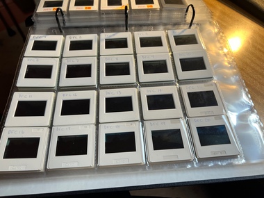 Melbourne Tram Museum
Album - David Frost Slide Collection, David Frost
Photo - see pdf file for further information. Number Brief Description date DFC1 A general view from the former railway platform at Port Melb Station looking towards Station Pier on opening day 20-12-1987 DFC2 A2 285 in the Tramway Platform at Port Melbourne Station on opening Day 20-12-1987 DFC3 A2 285 in the Tramway Platform at Port Melbourne Station on opening Day 20-12-1987 DFC4 A2 285 in the Tramway Platform at Port Melbourne Station on opening Day 20-12-1987 DFC5 A2 273 at St Kilda Tramway Station on opening day 22-11-1987 DFC6 A2 273 turning from Fitzroy St into St Kilda Tramway Station on opening day 22-11-1987 DFC7 B1 2001 at St Kilda Tramway Station turning into Fitzroy St on opening day 22-11-1987 DFC8 B1 2002 enters St Kilda Tramway Station on opening day 22-11-1987 DFC9 An A2 approaches St Kilda Tramway Station on opening day 22-11-1987 DFC10 Concreting the connecting curve from Fitroy St into St Kilda Station c July 1987 DFC11 An MTA AEC MKVI bus in Grey St St Kilda at Dalgety St with Tramway works in the background c July 1987 DFC12 Grey St St Kilda at Dalgety St with Tramway works in the background in Fitzroy St c July 1987 DFC13 Concreting the connecting curve from Fitroy St into St Kilda Station c July 1987 DFC14 Restaurant Tram 442 in Fitzroy St at Grey St Passing MTA bus 59 outside St Kilda Station c1986 DFC15 Former VR tram stop sign painted on a pole at Glenhuntly Rd & Broadway DFC16 Former VR Elwood Tram Depot under demolition 1996 DFC17 Former VR Elwood Tram Depot under demolition 1996 DFC18 Former VR Elwood Tram Depot under demolition 1996 DFC19 Former VR Elwood Tram Depot under demolition 1996 DFC20 Former VR Elwood Tram Depot under demolition 1996 DFC21 Former VR Elwood Tram Depot under demolition 1996 DFC22 Former VR Elwood Tram Depot under demolition 1996 DFC23 Former VR Elwood Tram Depot under demolition 1996 DFC24 MTS Tower waggon in use at the former VR Elwood Tram Depot under demolition 1996 DFC25 A Sign advertising the sale of the Former VR Elwood Tram Depot – 10/8/1996 1996 DFC26 Former VR Elwood Tram Depot under demolition 1996 DFC27 Interior of a shed at the former VR Elwood Tram Depot under demolition 1996 DFC28 Former VR Elwood Tram Depot under demolition 1996 DFC29 Former VR Elwood Tram Depot under demolition 1996 DFC30 Former VR Elwood Tram Depot under demolition 1996 DFC31 VR 20, former breakdown car in Bob Prentice’s Back Yard Jan 1974 DFC32 VR 20 on a low loader en route to Bob Prentice’s for preservation 1959 DFC33 VR 20 as the breakdown car on the St Kilda Electric Street Railway c1955 DFC34 VR 39 waits in St Kilda St as breakdown car 20 enters Elwood Depot c1955 DFC35 VR 54 and 50 in the rear yard of Elwood Depot c1958 DFC36 VR 50 in the rear yard of Elwood Depot c1958 DFC37 VR 50 in the rear yard of Elwood Depot c1958 DFC38 VR 28 in St Kilda St outside Elwood depot after the line had been cut back to this point c1958 DFC39 VR 29 in St Kilda St outside Elwood depot after the line had been cut back to this point c1958 DFC40 VR 35 passes 28 on the St Kilda Electric Street Railway c1955 DFC41 VR 39 on the St Kilda Electric Street Railway c1955 DFC42 Y1 613 on a tour c1970 DFC43 VR 54 in St Kilda St outside Elwood Depot c1955 DFC44 VR 28 at Brighton Beach Terminus c1955 DFC45 VR 33 being washed in the wash bay at the rear of Elwood Depot c1955 DFC46 VR 20 breakdown car running into Elwood Depot c1955 DFC47 VR 3 in the rear yard at Elwood Depot c1955 DFC48 VR 51 on an AETA Tour running out of Elwood Depot c1958 DFC49 VR 28 on the St Kilda Electric Street Railway c1955 DFC50 VR 28 with crew in St Kilda St outside Elwood depot after the line had been cut back to this point 1959 DFC51 VR 52 in Grey St near Fitzroy St c1958 DFC52 VR 51 on a AETA Tour passes 33 in Grey St near Fitzroy St c1958 DFC53 VR 29 in Grey St near Fitzroy St c1958 DFC54 VR51 on an AETA Tour shunts as 52 waits on the St Kilda Electric Street Railway c1958 DFC55 VR 51 on the Black Rock Electric Street Railway c1955 DFC56 VR 28 in St Kilda St outside Elwood depot after the line had been cut back to this point c1958 DFC57 Combined Rail-Tram Tickets of the Black Rock Electric Street Railway Feb 1975 DFC58 Combined Rail-Tram Tickets of the St Kilda Electric Street Railway Feb 1975 DFC59 Electric Street Railway & Motor Coach Paper Tear off Tickets Feb 1975 DFC60 VR 52 & 53 on Rt 82 pass in Cordite Ave near Wests Rd Sept 1975 DFC61 Z 68 & 52 in East Preston Depot in M&MTB Livery c1977 DFC62 Copy photo of VR 18 in Elwood Depot c1910 DFC63 VR 51 as a one man car at Black Rock Terminus c1955 DFC64 VR 53 on Rt 82 in Droop St Footscray Jan 1974 DFC65 B2 2027 on Rt 96 in South Melb Station c1988 DFC66 VR 20 as preserved in Bob Prentice’s backyard High St Prahran Jan 1974 DFC67 VR 700 on Rt 82 in Droop St Footsray c1978 DFC68 VR 28 as the last car from ST Kilda Station 28-2-1959 DFC69 VR 700 at the Rt 82 Moonee Ponds Terminus c1978 DFC70 VR 52 waiting time at the Rt 82 Footscray Terminus, the driver intently stares at the bundy clock as the Braid and the Connie gossip Jul 1972 DFC71 VR 54 shunting outside Elwood Depot to return to St Kilda Station 1959 DFC72 SW6 969 in MTA Livery blocking the entrance to South Melb Depot presumably during the scratch ticket dispute Jan 1990 DFC73 VR 52 & 53 on Rt 82 pass in Droop St Footscray Sept 1975 DFC74 VR 700 after withdrawl in the Newport Railway museum in the process of a repaint c1985 DFC75 VR 700 after withdrawl in the Newport Railway museum in the process of a repaint c1985 DFC76 VR 700 on Rt 82 in Droop St Footsray at The Cresent c1978 DFC77 VR 700 on Rt 82 in Droop St Footsray c1978 DFC78 Former VR tram depot in use as an MTA Bus depot c1990 DFC79 VR 52 waiting time at the Rt 82 Footscray Terminus Jul 1972 DFC80 VR 52 waiting time at the Rt 82 Footscray Terminus with Connie changing the pole Jul 1972 DFC81 VR 52 at the Rt 82 Moonee Ponds Terminus with the crew chatting 7-12-1974 DFC82 VR 52 on Rt 82 on the reserved track in Raleigh Rd Ascot Vale Jan 1974 DFC83 VR 53 on Rt 82 in Leeds St Footscray about to turn into Hopkins St April 1976 DFC84 VR 53 on Rt 82 in Droop St Footsray Jan 1974 DFC85 VR 700 on Rt 82 in Droop St Footsray at Hopkins St c1978 DFC86 Z 52 in MTA livery on Rt 19 in Elizabeth St near Bourke St c1985 DFC87 VR 52 at the Rt 82 Moonee Ponds Terminus Jul 1972 DFC88 VR 53 at the Rt 82 Footscray Terminus Jan 1974 DFC89 VR 52 freshly outshopped from the workshops and W7 1011 at the Bourke St Terminus with 52 on display for the 1968 railway exhibition 1968 DFC90 Painting of W class 369 in Chocolate & Cream c1930 DFC91 Charing Cross, Bendigo at night c1965 DFC92 Ballarat ? c1965 DFC93 Bendigo 18 on an AETA tour in McCrae St near Tramway Ave c1965 DFC94 View from the roof of a tram in the body shop at Preston Workshops 1977 DFC95 View from the roof of a tram in the body shop at Preston Workshops 1977 DFC96 View from the roof of a tram in the body shop at Preston Workshops showing the panto on 546 1977 DFC97 Interior view of Carlton Control Centre showing desk and wall panel c1968 DFC98 W2 493 on Rt 55 in Kingsway outside South Melb Depot Aug 1973 DFC99 W2 496 in Sturt St at Kingsway on Rt 1 Jul 1973 DFC100 Z class truck c1975 DFC101 Z3 116 in Bourke St at King St as new c1979 DFC102 Bob Prentice on tour c1968 DFC103 SW6 900 as an advertising tram for Newsday at night 1969 DFC104 597 Jul 1973 DFC105 W2 480 on Rt 3 passing under the railway bridge at Caulfield Oct 1972 DFC106 Interior view of Carlton Control Centre showing desk c1968 DFC107 SW6 856 on Rt 77 at night Jul 1973 DFC108 W2 496 in Sturt St at Kingsway on Rt 1 Jul 1973 DFC109 PCC 980 on a tour at South Melb Depot c1968 DFC110 SW6 856 on Rt 77 at night Jul 1973 DFC111 View from the roof of a tram in the body shop at Preston Workshops showing the panto on 546 1977 DFC112 Dandenong Rd from Chapel St Nov 1968 DFC113 A Z class car turns from Gertrude into Nicholson St c1990 DFC114 SW6 900 as an advertising tram for Newsday at night 1969 DFC115 Port Melbourne Station showing Centennial bridge and station building prior to closure. 10-1987 DFC116 Port Melbourne station with train prior to closure, looking south 10-1987 Demonstrates the work of David Frost in photography and or collecting slides.Assembled album in a black presentation folder of 116 colour slides, 6 slide sleeves, collected or photographed by David Frost. Many are TMSV or Windsor Publications slides. All photographs have been scanned and placed on the Museum's G drive. A list of all photographs with details has been compiled. melbourne, tramways, trams, vr trams, elwood, st kilda light rail, port melbourne, opening, elwood depot, buses -
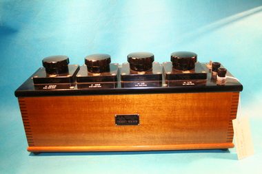 The Ed Muirhead Physics Museum
Resistance Decade Box, mid-20th Century
This object is believed to be associated with training at the Parkville Secondary Teaching College during the 20th Century.Related to objects 450 and 452This rectangular wooden resistance decade box features four large dials for controlling resistances. The dials are mounted atop a black plastic panel, each with a square base. Three smaller dials are mounted to the right of the large dials.Embossed plaque at front: 'J. L. WILLIAM / SCIENTIFIC INSTRUMENTS / SERIAL No 3960 / TYPE RB4DS / MELBOURNE / AUSTRALIA' Engraved and filled white on top plate from left to right: 'ABSOLUTE OHMS AT 20 C / MANGANIN' Logo reading: 'J. L. WILLIAM / SCIENTIFIC / INSTRUMENTS / MELBOURNE / SERIAL No 3960' 'ZERO RESISTANCE / 0.004 OHM' Engraved on back edge of top panel: 'SECONDARY TEACHER COLLEGE PARKVILLE' Dials are labelled underneath with unit measurements for resistance settings, engraved and in-filled white.j. l. william, decade box, electrical equipment, resistance decade box, scientific instruments -
 Flagstaff Hill Maritime Museum and Village
Functional object - Bellows, 1862-1875
This bellows was used at the Warrnambool Racecourse by Master Farrier, Brian Chapman (1931-2017), during the 1970s but its history before then is still being investigated. The bellows have continued to be used from 1978 at Flagstaff Hill's blacksmith's workshop. Even today, in 2021, this same bellows are used by a volunteer blacksmith as he demonstrate the skills and tells of the importance of the blacksmith trade to colonial Australia. This 1860s double-action bellows is a typical form of blacksmith's or shipsmith's bellows. The end is forge-fitted with an iron nozzle or tube, called a tuyere or Tue iron, which concentrates the air to fan the fire or furnace. Tuyeres were traditionally made of cow horn. The double-action design of this bellows efficiently moves air both in and out of the chambers in the one movement of the long handle. The bellows was manufactured by John C. Onions of Birmingham, England, between 1862 and 1875. The stamp with the text, Gold Medal 1862, was also used on the business’ advertising. In 1875 the company was registered and began using the name John C. Onions Limited. JOHN C. ONIONS - John C. (Collingwood) Onions (1841-1904) was the son of a bellows maker of the same name. Onions (born 1841) and his wife Helen married in 1867 and they named one of their children John Collingwood Onions (1868-1913), as was the family tradition. He was well known as a Birmingham manufacturer of patented bellows and other forge-related equipment. He sold to the wholesale and retail markets for both local and overseas customers, including the British colonies. An 1862 advertisement points out that John C. Onions was a “Bellows manufacturer and contractor to Her Majesty’s Honourable Board of Ordinance” and His Imperial Majesty the Emperor of the French [Napoleon Bonaparte]”. The advertisement includes a sketched portrait of the Emperor Napoleon III, and an Imperial Autograph Letter dated May 23, 1854, from Napoleon, Palace of the Tulleries to Mr J C Onions of Bradford Street, Birmingham. In 1863 the company registered a patent on portable forges. In 1871 there were eight employees. John C. Onions Limited became a registered company in 1875. In 1876 an advertisements included that the company were smiths for hearths and tools in general and showed a row of six medallions including one with “Napoleon III, Emperor” and his portrait, and another “ _ _ _ 1862 MEDAL”. Their advertising motto was “For Excellence of Quality”. In 1885 the company merged with William Allday and Sons to become Allday and Onions. This mid-19th century bellows has local historical significance as it were once used by blacksmiths at the Warrnambool Racecourse in the annual racing event that continues today. This bellows is significant as a working example of equipment used in the 1800 and 1900s in the trace of blacksmiths and other metal working smiths. The bellows is technologically significant as it shows the progress from simple bellows to the double-action bellows, a time saving and efficient improvement. The manufacturer John C. Onions is historically significant as a family business that began in the 1600s and continued up until the 1980s.Bellows; large, oval, mechanical double-action smith’s bellows, manually operated, in working condition. The paddles of wood that form the top, middle sections and base of the bellows have flexible leather pieces attached firmly between them, forming airtight double lungs. Cut-outs in the panels allow the bellows to fill with air then force it out. A long handle is connected to pump the bellows and control the quantity and force of the air. The blasts of air are forced through the metal nozzle or tuyere at the end of the bellows and into the forge’s fire. Inscriptions are impressed into the wood on the upper paddle or board of the bellows. There are three circular stamps containing text. Text impressed in the wooden upper paddle of the bellows has been assumed to read “JOHN C. ONIONS, PATENTEES & MANUFACTURERS, BIRMINGHAM””?” “EXTRA” “AWARDED FOR EXCELLENCE OF QUALITY”, made from the following readable text :- “JOHN C ONIONS“ “PATENT - - - & MAN - - - - - - - - -“, “BIR - - - - HAM“, “ _ ERA - - - - “- XTRA-“, “- - - - - - - FOR EXCELL-“ “OF - - - - ITY” Text in the stamp “ - - ECE - - “, “ - - - - - / 1862 / MEDAL”, “- ITY” flagstaff hill, warrnambool, shipwrecked-coast, flagstaff-hill, flagstaff-hill-maritime-museum, maritime-museum, shipwreck-coast, flagstaff-hill-maritime-village, john collingwood onions, john c onions, allday and onions, bellows, smith’s bellows, 19th century bellows, double-action bellows, double-acting bellows, double lung bellows, double chamber bellows, blacksmith tools, blacksmith trade, blacksmith craft, blacksmith equipment, forging equipment, john c onions patented double-action bellows, brian chapman, warrnambool racecourse, blacksmith, shipsmith, iron smith, mechanical bellows -
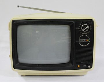 Wodonga & District Historical Society Inc
Functional object - Sanyo VHF Colour Television 1980
The Sanyo VHF colour television is thought to have been assembled in Wodonga, as Sanyo was one of the international companies that set up business in Wodonga in the 1970s as part of the de-centralisation of industry and continued operation into the 1980s. The Sanyo Australia Pty. Ltd. factory in Wodonga opened in 1974 with 35 staff and production peaked in 1976-1977 when it employed 360 people. In the first ten years 350,000 televisions were assembled from Japanese parts, however by 1984 the number of staff had reduced to 112 and the factory closed in 1987. All Sanyo televisions were then imported from Japan. The Sanyo VHF colour television has local, state and national significance as it is thought to have been assembled in Sanyo Australia's factory in Wodonga. Sanyo was one of the international companies that set up business in Wodonga as part of the decentralisation of industry in Australia in the 1970s-1980s.Cream and black plastic Sanyo VHF colour televison, with the Sanyo logo and one large circular VHF control knob for the different channels on the proper left black plastic panel, and one small off-on volume knob at the bottom of the black plastic panel. The diagonal screen measurement is 30 cm or 11 inches."VHF" / SANYO / Telecolor / AFT / OFF-ON/ VOLUME" on the proper left black plastic panel on the front of the television. "75Ω- 300Ω" on the black part of the cable attached to the two antennas. "FOR YOUR SAFETY / Install any external / aerial to AS1417.1" on the back of the television. "SERIAL NO / 30207332" on the back of the television. "SANYO / MODEL CTP 2600 / CHASSIS NO. 79P-B5ZH 01 / AC 240V~, 50Hz, 85 WATTS / SANYO ELECTRIC CO., LTD. MADE IN JAPAN / WARNING / DANGEROUS VOLTAGE INSIDE / CHASSIS LIVE / CONTACT IS DANGEROUS / 3401901 B5ZH-B" on the back of the television. "SBS TELEVISION" stickers on both sides of the television. "WODONGA ASSEMBLED TELEVISION. (underlined) / This SANYO VHF COLOUR TELEVISION / Serial number AS1417.A (AS = Australia) / Model CTP 2600 was assembled / at the Sanyo Drive, Wodonga, factory Circa 1980, from Japanese parts." printed on a paper label attached to the upper back part of the television. sanyo, sanyo colour televisions, sanyo t.v.s, vhf t.v.s, sbs, wodonga, sanyo australia pty. ltd.