Showing 96 items matching "spillway"
-
 Bendigo Historical Society Inc.
Document - Directions to Lake Eppalock with road descriptions and map
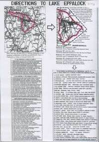
John Perry Collection. Laminated copy of 'Directions to Lake Eppalock'. Gives directions in relationship of Lake Eppalock to Bendigo, Kyneton and Heathcote. Undated. Gives basic descriptions of bridges on lakebed, ford crossings on lakebed and inundated dwellings on lakebed. The dam was built by the State Rivers and Water Supply Commission of Victoria. The dam wall height is 45 metres (148 ft) and the main embankment is 1,041 metres (3,415 ft) long. At 100% capacity the dam wall was designed to hold back 304,651 megalitres (6.7014×10¹⁰ imp gal; 8.0480×10¹⁰ US gal) of water. The surface area of Lake Eppalock is 3,011 hectares (7,440 acres) and the catchment area is 2,124 square kilometres (820 sq mi). The controlled spillway is capable of discharging 8,040 cubic metres per second (284,000 cu ft/s). Lake Eppalock supplies both stock and domestic water to the Campaspe irrigation district. It also serves as a water supply to Bendigo and Heathcote and, in more recent times, Ballarat. The lake is a major attraction for those engaging in watersports, with a number of tourist parks and accommodation facilities available. Permissible activities on the lake include high-speed boating, water skiing, sailing, canoeing, fishing and swimming. The lake's water levels were low for approximately eight years between 2002 and 2010 during a prolonged drought, which restricted the amount of recreational activity until rainfall in the latter half of 2010 returned the lake to 100 percent capacity. Built between 1961 and 1964, Lake Eppalock remains the only water storage on the Campaspe River system.water, dam, directions, eppalock -
 Wodonga & District Historical Society Inc
Album - Hume Reservoir Australia Album - General View of Works from New South Wales end, Looking Upstream, August 1927
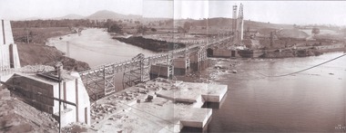
This set of photos is from a leather bound album bearing the inscription "HUME RESERVOIR AUSTRALIA" plus 'The Rt. Hon. L. C. M. S. Amery, P. C., M .P.' all inscribed in gold. It was presented to The Rt. Hon. L. C. M. S. Amery, P. C., M. P, Secretary of State for Dominion Affairs on the occasion of his visit to the Hume Reservoir on 2nd November 1927. This album is of local and national significance as it documents the planning and development of the Hume Reservoir up to 1927. It was the largest water reservoir in the British Empire. The album records the pioneering engineering work that went into its construction.DEPARTMENT OF PUBLIC WORKS, N.S.W. RIVER MURRAY WATERS SCHEME. HUME RESERVOIR. 22. General View of Works from New South Wales end, Looking Upstream. Features: At the left, part of the North Wing Wall, the highest part of which is 26 feet below its ultimate height. Below in the foreground is the portion of the dam where provision is to be made for hydro-electric generation. The tubes, three in number, 13 feet in diameter, will be laid on the level shown and an early start will be made in laying them. The level for the other four regulating outlets, 9 feet in diameter, together with a part of the spillway section of the dam, is underwater at this stage and it may be remarked that at one point, about half way across the channel where the water is now flowing, the concrete foundations are about 80 feet below the level of the water. The broken surface of the water is due to the large “plums” in the concrete. The still water in the right foreground is the stilling pool over the concrete floor of which there is now more than 20 feet of water and by means of which the discharge from the outlet pipes will be quelled. The trestlework on the upstream side of the dam carries the concrete belt conveyor. It extends from the concrete mixer house, which is out of the picture, behind the wing wall, along almost the entire length of the concrete portion of the dam. The concrete is discharged from the belt at any desired point by means of trippers, one of which may be seen over the second trestle. On the other side of the flowing water is the coffer dam. A channel 300 feet wide involving about 140,000 cubic yards of excavation and dug for the temporary diversion of the river as it is flowing now. To the right top of the view beyond the Coffer Dam is the earth embankment being thrown across the major part of the valley by the Victorian Constructing Authority. The Mitta Mitta River flows into the Murray at the far end of the reach of water on the left. August 1927.hume reservoir australia, river murray waters scheme, hume reservoir construction -
 Federation University Historical Collection
Book, The Melbourne Technical College Hydraulic Engineering
Two volumes of course notes for the course of Hydraulic Engineering at the Melbourne Technical Collegehydraulic engineering, melbourne technical college, rmit, rex hollioake, leakage, aquaducts, dams, spillways, ground water, pumping, curvss, pipes, reservoirs, tanks, weir, channel, water supply, sewerage, sewers, sewerage treatment, drainage -
 Kiewa Valley Historical Society
Photograph of Lake Guy and Bogong Village, Lake Guy and Bogong Village, Approx. 1945
In 1940 Field Headquarters for the Kiewa Scheme were established at Bogong with office, workshop facilities and accommodation for workmen, staff and some families constructed. (There had been a 'tent camp' on this site in 1939 but was destroyed by bushfires) Construction of accommodation continued until 1947. A total of 40 houses plus a hostel for single staff, post office, police station, medical centre and primary school all with water and sewerage and electricity supply. The staff hostel was known as Kiewa House and is now occupied by the Education Department. Lake Guy was named after Mr. L.T. Guy who was the Resident Engineer in charge of construction work and associated activities on the Kiewa area. He held this position from 1939 to November 1946 when he was transferred to Head Office.This photograph is an excellent historical record of Bogong Village in about 1945. It shows the layout of the town in the fairly steep terrain, the workmen's camp between the houses and the lake foreshore, the Commissioner's Lodge on the hill behind the Village, the walkway through the dam wall can be seen to the left of the spillway, the dam is on spill and note damage to the large trees is still evident from the 1939 bush fires. The Commissioner's Lodge was lost in the 2003 fires and the camp buildings were in service until 1962, when they were removed and the site converted into a public picnic area with lawns and gardens.A Black and white photograph"Lake Guy and Bogong" hand written on back of photograph.kiewa, accommodation, lake, dam, bogong -
 Kiewa Valley Historical Society
Photograph of Lake Guy Dam, Spillway, Lake Guy Dam, c1945
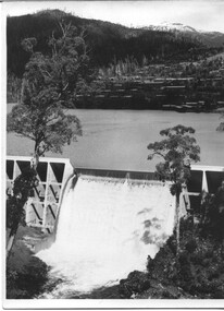
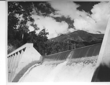
In December 1939 the excavation of the diversion tunnel at the site of Junction (Lake Guy) Dam was commenced and finished in February, 1940.This allowed the stream to be diverted to facilitate the dam wall construction. This is a 'slab and buttress' dam. It is framed with timber and concrete then poured into the structure. A contract was let to Lewis Construction Co. for the construction of the dam, and the first batch of concrete was placed in September, 1940. Industrial trouble caused some delays but there was also slow progress on the part of the contractor and the work was taken over by the S.E.C., terminating the contract. The dam was completed in March, 1944. The lake is named after Mr. L.T. Guy who was the Resident Engineer, in charge of construction work and associated activities on the Kiewa area, from 1939 until November 1946. An historical pictorial record taken for the State Electricity Commission of Junction Dam (Lake Guy) on spill. Mt. Arthur is in the background and there is still evidence of the destruction of trees from the 1939 bushfires. Black and white photograph of Lake Guy Dam . The dam is spilling and Mt. Arthur is in the background. Hand written on back of photograph in blue ink " Lake Guy Dam".dam, lake, water, mr. l.t.guy -
 Federation University Historical Collection
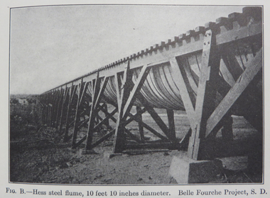
Book, Irrigation Practice and Engineering Volume 2: Conveyance of Water and Volume 3: Irrigation Structures and Distribution System by B.A. Etchevery, 1915 and 1916
Blue hard covered books. .2) Volume III Irrrigation Structures and Distrubution Systemirrigation, water canals, tunnels, flumes, pipes, concrete pipes, wrought iron and steel pipes, wooden pipes, california, diversion works, weirs, spillways, canals, check gates, railroad crossing, america, united states of america, university of california, yellowstone river, colorado, arizona, windlass hoist, twin falls, idaho, arkansas valley, truckee-carson, salmon river, umatilla, cippoletti weir box