Showing 256 items
matching engineering drawing
-
 Maldon Vintage Machinery Museum Inc
Drawing Machine, Pre WW2
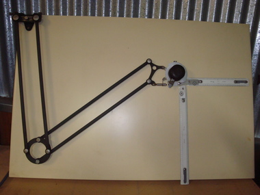
"Ray & Gilbert" articulated arm type manual drawing machine as used in a drawing office. Fitted with "W & G" scale rulers. Rulers are plastic coated timber. Black arms and handle, white rulers. Mounted on a wooden drawing board.. .4) Metal adjusting spanner..1) At mounting pivot point of drawing machine "Ray & Gilbert / Drafting Machine / Serial No. ? / Melbourne. Aust." .2) Scale rule "W & G E 18". .3) Scale rule "W & G E 12". .4) No inscriptions.drafting, engineering -
 Maldon Vintage Machinery Museum Inc
Drawing Machine, Pre WW2
"Ray & Gilbert" articulated arm type manual drawing machine as used in a drawing office. Fitted with "W & G" scale rulers. Rulers are plastic coated timber. Black arms and handle, white rulers. Mounted on a wooden drawing board. Almost identical to VMVM 113.3 but in better condition. .4) Metal adjusting spannerSimilar to VMVM 113.4drafting, engineering -
Maldon Vintage Machinery Museum Inc
Drawing Machine
Articulated arm type manual drawing machine with grey crachle finish. Very dark brown handle, chromed fittings. W&G scale rulers."Ray & Gilbert Pty Ltd / Serial No. 21XT"drafting, engineering -
Maldon Vintage Machinery Museum Inc
French Curves
.1) Wooden box with hinged lid. 22 wooden and 3 plastic flat curved patterns loose in the box. Several are numbered. .2) 3 clear plastic curves in a pouch. Made in Italy. .3) 3 clear plastic curves in a pouch. Made in Italy. .3 .....31) Plastic curves. French curves are used in a drawing office to draw a smooth best fit line through a number of points..25) "42 / Engineering / TB5" etched into plastic. .2 & .2) Pouches marked "LONGO Made in Italy" in gold.trades, drafting -
 Ballarat Tramway Museum
Magazine - Report, N. F. Henley, "Tramcar Truck Development", 1990
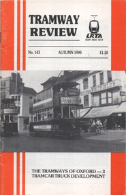
Contains an article that looks at the development of the four wheel Brill 21E in regard to the engineering aspects. Written by N. F Henley with drawings of the various concepts and history of the Brill truck. See item 7384 for s similar article on the Brill 22E truck.Yields information about the development of the Brill 21E truck which is used on some of the BTM trams.Magazine 40 pages, centre stapled, Tramway Review published by the Light Railway Transit Association, Autumn 1990.trams, tramways, bogies, trucks, brill trucks, brill 21e -
 Ballarat Tramway Museum
Document - Report, N. F. Henley, "The development of the Manchester bogie", 1988
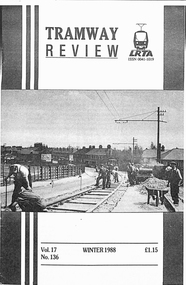
Article looks at the development of the maximum traction bogie, the Brill 22E in regard to the engineering aspects. Written by N. F Henley with drawings of the various concepts and history of the Brill truck. See item 9663 for s similar article on the Brill 21E truck.Yields information about the development of the Brill 22E truck which is used on some of the BTM trams.Seven A4 sheets, photocopy of an article titled "The development of the Manchester bogie" from the UK magazine Tramway Review published by the Light Railway Transit Association, Winter 1988.trams, tramways, maximum traction, bogies, trucks, brill trucks -
 Melbourne Tram Museum
Document - Comeng - All Electric Trams - Tender document, Commonwealth Engineering - Comeng, 1972
Folder prepared by Commonwealth Engineering "Comeng" to document their tender offer for the future Z class trams. Includes drawings SCH9273 and 9274 giving an elevation and plan of their proposal, a coloured illustration which is based on PCC tram 1041, notes on the specification dated 11/11/1972, Duwag documentation and photographs, interiors, alternatives and suppliers. Does not include a formal tendered price. See item 7200 for the final contract document.Demonstrates the Commonwealth Engineering 1972 proposal for the contract for the Z class tram.Plastic folder with three interscrews containing the contract tender documentation for the future Z class tram. Includes a copy of the Tender Schedule for "100 All-Electric trams" in a front cover pocket and many loose items in a rear pocked, includes drawings, photographs and documentation. Has "Comeng" in gold block on the front. Folder by Arnold's plastics of Sydney.tramways, mmtb, z class, tenders, new trams, comeng, commonwealth engineering, contracts -
 Melbourne Tram Museum
Administrative record - Contract bid documents, Commonwealth Engineering - Comeng, "Comeng – submission bid – to build artic trams (Contract 4000) – March 1984.", Mar. 1984
Large set of photocopied documents - titled "Comeng – submission bid – to build artic trams (Contract 4000) – March 1984" - B class trams .1 - Book 1 - Commercial submission - tender response, commercial payment, schedules. .2 - Book 2 - Technical submissions, equipment from AEG, GEC, ACEC, Brush, Mitsubishi, Ganz Electric, Holec, Itoh/Garrett/Hitachi and Stromberg, drawings, and alternatives, options. Also looks at the financial aspects. Documents not in order but marked what they are. All documents stored in a single box - taped together. Dated March 1984. Has a table of contents.trams, tramways, mta, the met, b class, tenders, specification, comeng, commonwealth engineering -
 Melbourne Tram Museum
Drawing, Commonwealth Engineering - Comeng, "Comeng (Vic) Pty Ltd - Dandenong Plant", 1985?
... Trams tramways Comeng Commonwealth Engineering Tramcar ...Drawing - A3 photocopy of the "Comeng (Vic) Pty Ltd - Dandenong Plant", showing the layout of the various buildings and Trackwork for the construction of tramcars and other railway rolling stock. Shows the various building numbers but no description of which building is used for what purpose. Shows a double ended tram testing track with two loops, probably at the time of the construction of the Hong Kong cars. Possibly produced for an AETA or similar body tour of the plant, c1985 The Google Earth view, accessed at the time of cataloguing shows that these loops no longer exist, but the tram testing track is still in position.trams, tramways, comeng, commonwealth engineering, tramcar manufacture, hong kong, tramcar construction -
 Federation University Historical Collection
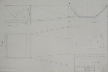
Drawing - Engineering drawings, Technical drawing, 1960
... ) Crane bogey Technical drawing Drawing Engineering drawings ...pencil on paper student's technical drawings .1) Ogee weir .2) Roof truss .3) R.C.tank, 780 gals .3) Crane bogeytechnical drawing, engineer drawings, chemistry, e.juris, school of mines ballarat -
 Federation University Historical Collection
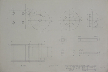
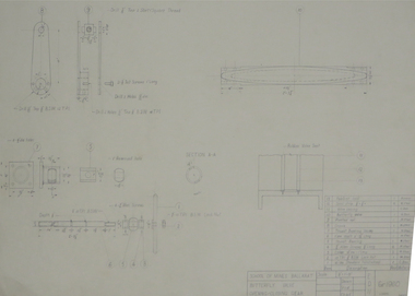
Drawing - Student's Technical Drawing, Technical drawing, 1964
... technical drawing mechanical engineering k.e. maddocks ...pencil on paper student's technical drawing: winch to lift 1 cwttechnical drawing, mechanical engineering, k.e. maddocks, school of mines ballarat -
 Federation University Historical Collection
Drawing - Engineering drawings, Technical drawings, 1960
... - details Technical drawings Drawing Engineering drawings ...Student's technical drawings .1) sheet 1 -assembly .2) sheet 2 - detailstechnical drawing, k.o.rogers, school of mines ballarat -
 Federation University Historical Collection
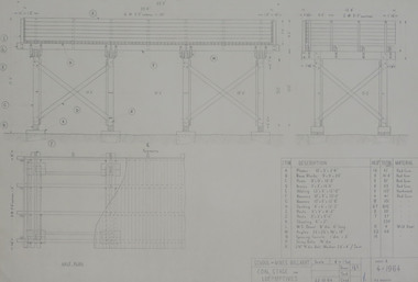
Drawing - Engineering drawings, Technical drawings, 1964
... details Technical drawings Drawing Engineering drawings ...pencil on paper student's technical drawings .1) Coal stage for locomotive - assembyy .2) Coal stage for locomotive - connection detailstechnical drawing, p. j. shedden, school of mines ballarat -
 Federation University Historical Collection
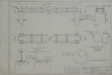
Drawing - Student's Technical Drawing, Technical drawing, 1951
... technical drawing civil engineering f. benjamin School ...Pencil on paper student's technical drawing of a waterpipe spanning creektechnical drawing, civil engineering, f. benjamin, school of mines ballarat -
 Melbourne Tram Museum
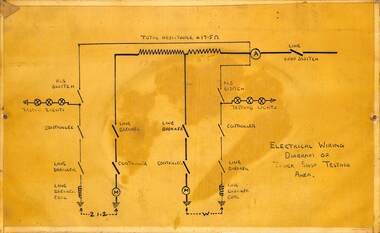
Sign - Drawing, Melbourne & Metropolitan Tramways Board (MMTB), Electrical Wiring - diagram of Truck Shop Testing Area
... trucks Truck Shop Preston Workshops electrical engineering ...Prepared by Preston Workshops staff, in the Truck Shop, to show the electrical apparatus line diagrams for testing of motors in a bogie or truck.Demonstrates the equipment used to test tramcar bogies or trucks prior to fitting to a tramcar.Drawing - dyeline print taped and edged to a piece of masonite. Has two screw holes for mounting on either side.trams, tramcars, bogies, trucks, truck shop, preston workshops, electrical engineering, electrical equipment -
Merbein District Historical Society
Drawing, Folio, Engineering Drawings, 1944-1949
... Stack Williams Maurie Folio, Engineering Drawings Drawing ...agricultural equipment, industrial equipment, building industry, tractors, merbein co-op, implements, block equipment, williams & lawler, les stack, williams maurie -
 Melbourne Tram Museum
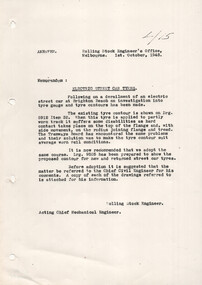
Document - Report and Drawing, Victorian Railways (VR), "Electric Street car tyres", 1-10-1948
Report photocopied from VR Engineering files titled "Electric Street car tyres" detailing issues with worn track and tram tyres resulting in derailments. Notes after discussions with the MMTB, changed the profile to suit average worn rail conditions. The attached drawing does not seem to relate to the report as different drawing numbers given. For Melbourne tyres - see drawings R6320 and R12-279.Yields information about issues with tramcar wheels.Report - photocopied - two A4 sheets of paper.trams, railways, vr trams, wheels, wheel profiles, tyres, derailments -
Federation University Historical Collection
Plan - Student's Technical Drawings, Technical drawings, 1960s
... technical drawing mechanical engineering turf roller Pencil ...Pencil on paper student's technical drawings Turf Roller: .1) Assembly .2) Components technical drawing, mechanical engineering, turf roller -
 Federation University Historical Collection
Plan - Student's Technical Drawings, Technical drawings for a Turf Roller, 1966
... technical drawing mechanical engineering Pencil on paper ...Pencil on paper student's technical drawings Turf Roller: .1) Assembly .2) Details - frame .3) - .4) Details technical drawing, mechanical engineering -
 Federation University Historical Collection
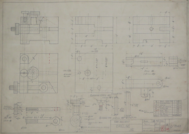
Drawing - Student's Technical Drawing, Drilling Jig Technical Drawing, 1949
... technical drawing mechanical engineering g carroll drilling ...Pencil on paper student's technical drawing of drilling rig technical drawing, mechanical engineering, g carroll, drilling rig, ballarat school of mines -
 Federation University Historical Collection
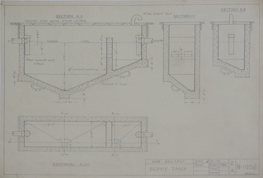
Drawing - Student's Technical Drawing, Technical Drawing, 1952
... technical drawing civil engineering geology ian witcher ...Pencil on paper student's technical drawing of a Septic Tanktechnical drawing, civil engineering, geology, ian witcher, school of mines ballarat -
 Melbourne Tram Museum
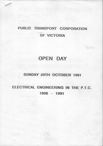
Document - Report, Public Transport Corporation (PTC), "Electrical Engineering in the PTC 1906 - 1991", Oct. 1991
Report or Programme for the Sunday 20th October 1991, PTC Open Day 23 A4 photocopied sheets + A3 folded drawing stapled in the top left hand corner titled "Electrical Engineering in the PTC 1906 - 1991". Describes the history of electric traction systems and engineering in Victoria for both rail and tram operations, overhead wiring systems, lighting and power supplies, with photos of Newport Power Station, Jolimont, Camberwell, Preston tramway substations. The last sheet has a drawing, poor quality of the 1500V DC railway traction system.trams, tramways, ptc, overhead, substation, electrical engineering, electric traction, open days -
 Melbourne Tram Museum
Drawing, The Met, Electrical drawings for Z1 and Z2 tramcars, c1995
Black plastic folder with black plastic comb binder containing plasticized drawings for the Z1 and Z2 class tram circuits (45 pages), Z3 tramcars (47 sheets), notes on the CCU Test cards and performance and a list of controller wiring diagrams, for all tramcars and some of the associated drawings. Prepared by the Met Tram Servicing branch. Not dated.trams, tramways, z class, instructions, controllers, electrical engineering, electrical equipment, electrical systems, z3 class -
 Melbourne Tram Museum
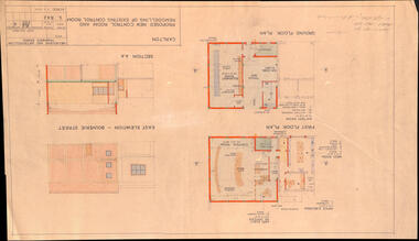
Drawing, Melbourne & Metropolitan Tramways Board (MMTB), "Carlton - Proposed new control room and remodelling of existing control room", May. 1961
Drawing - titled - "Carlton - Proposed new control room and remodelling of existing control room", coloured with a water colour brush, showing the proposed extensions to the Carlton control room, drawing Number S842, dated 9-5-1961. Shows the ground and first floors, mess room, offices, stairs and control room layout. Has the external elevations and sections.Has some pencil notations front and back re lights and sketch.trams, tramways, carlton, control centre, power supply, electrical engineering, electrical switching -
 Melbourne Tram Museum
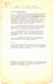
Document - Report, F R Thompson", "PCC - by F R Thompson", early 1960's
Report - four pages - stapled in top left hand corner, titled "PCC - by F R Thompson", describing the control systems in a PCC tramcar, eg No. 980. Refers to drawings that are not included. Describes the control circuits, car drive, equipment, electric brakes, emergency dynamic braking, and service braking.trams, tramways, tramcars, controllers, electrical engineering, electrical equipment, motors, electric traction, pcc -
 Melbourne Tram Museum
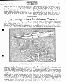
Document - Report, Electrical Engineer, The Electrical Engineer and Merchandiser, "Rail Grinding Machine for Melbourne Tramways", 1927 - 1950
Set of 6 reports, photocopied onto heat sensitive paper from various magazines. Documents match the image numbers. .1 - .2 pages - Electrical Engineer - 15/8/1928 - "Rail Grinding Machine for Melbourne Tramways" - Grinders .2 - 5 pages - Electrical Engineer - 15/6/`1927 - "Workshop of the Melbourne Tramways Board" - includes a layout drawing - See Reg Item 3675 for a reprint of this document. .3 - 1 sheet - Electrical Engineer - 15/9/1927 - "Worm Driver for Electric Tramcars - new type of truck constructed by Melbourne Tramways Board" - fitted to X1 class cars. Has a sketch of the truck. .4 - 8 pages - The Electrical Engineer and Merchandiser - 15/11/1933 - "A Supervisory Control system for Traction Substation - Equipment designed for the MMTB" - written by C. L. Steele. .5 - 8 pages - "Institute of Engineers Australia" - Dec. 1943 - "Prolonging the life of the tramway rail" - by A. H. Blanch. Note some pages have handwritten additions where the copying is out of line. .6 - 1 page - The Electrical Engineer and Merchandiser - 16-10-1950 - "Noiseless bogie for Tramcars" - PCC bogies. - St Louis Car C B-3 Bogie.trams, tramways, mmtb, rail grinding, rail wear, track materials, grinding, preston workshops, worm drive, x1 class, substation, electrical engineering, electrical equipment, tramway per way, bogies, pcc class -
 Melbourne Tram Museum
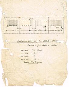
Drawing, "Resistance Diagram for Dick Kerr Boxes", c1960
Drawing in ink on paper, titled "Resistance Diagram for Dick Kerr Boxes", showing the set out of the resistance grids, the steps and the values in Ohms, of resistance for trams fitted with this type of equipment.trams, tramways, electrical engineering, electrical equipment, resistance grids, dick kerr -
 Melbourne Tram Museum
Document - Instruction, Westinghouse Traction Brake Co, "Westinghouse - T5001-1 SM3 Straight-Air Brake Equipment", Mar. 1927
Instruction - 64 pages + light brown card cover centre stapled with cloth binding on outer edge + fold out drawing inside the rear cover, titled "Westinghouse - T5001-1 SM3 Straight-Air Brake Equipment". Dated March 1927. Has a table of contents, outlines the rules of operating brake equipment fitted to tramcars, the SM3 and PV brake valves, SX2 brake valve, locomotive straight air, installation piping, wiring, maintenance - piston travel, lubrication, car tests, hints to Motormen and Conductors and General Hints. Includes instructions on compressors, air intakes, valves, cylinders and governors.On inside cover "Bob Prentice 13 High Street Prahran Vic 3181" and on top of first page "W. Armstrong"trams, tramways, electrical engineering, electrical equipment, westinghouse, air compressors, brakes, instructions, maintenance -
 Melbourne Tram Museum
Document - Instruction, General Electric, "General Electric - Motor Driven Air-Compressors Instruction Book 84591B", Jun. 1921
Instruction - 20 pages + brown covers, centre stapled, and two punched holes on left hand side, right hand side has rounded corners, titled "General Electric - Motor Driven Air-Compressors Instruction Book 84591B", dated June 1921. Includes instructions on GE Centre Gear Type self lubricating compressors, models CP25, 27, 28, 29, 30, 127, 128 and 130. Gives details of the parts, lubrication requirements, photos, drawings including connection diagrams. Last two pages includes notes on the Induction motor-driven air compressors CPT27, 28 and 30. Has a list of company offices on the rear cover.trams, tramways, electrical engineering, electrical equipment, general electric, air compressors, brakes, instructions, maintenance -
 Melbourne Tram Museum
Document - Instruction, Safety Car Devices Co. St Louis, "Instruction Pamphlet S-100, Air Brake and Safety Car Control Equipment", Jul. 1924
Instruction - 108 pages + 9 fold out drawings glued and stapled in at the rear + card covers with red cloth binding, rounded right hand edges, centre stapled. Titled "Instruction Pamphlet S-100, Air Brake and Safety Car Control Equipment", published July 1924 by the Safety Car Devices Co. St Louis. Includes the M28 Brake valve. Describes in detail the rules for operation, parts, description, M28 Brake Valves, Maintenance, Practical car tests, hints, defects. The 9 drawings at the rear of the document give detail arrangements of the piping and control equipment. Book scanned into three sections. See also Reg Item 3513 for another similar document.on top of first page "C. Hodgson"trams, tramways, electrical engineering, electrical equipment, air compressors, brakes, instructions, maintenance, controllers