Showing 46 items matching "drive chain"
-
 Friends of Westgarthtown
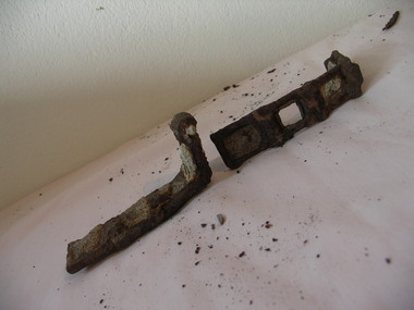
Agricultural drive chain
... Agricultural drive chain...drive chain...Two parts of an agricultural drive chain with rectangular... melbourne rural industry farm machinery drive chain machinery link ...Two parts of an agricultural drive chain with rectangular links. Both pieces are believed to be from the same chain and have rusted in to an L-shape.No visible markingsrural industry, farm machinery, drive chain, machinery, link, steel, forged, agriculture. -
 Orbost & District Historical Society
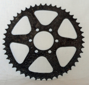
chain drive sprocket, first half 20th century
... chain drive sprocket...machinery chain-drive-sprocket...A black painted steel chain drive sprocket. It has six.... machinery chain-drive-sprocket A black painted steel chain drive ...Sprockets are used in machinery either to transmit rotary motion between two shafts where gears are unsuitable or to impart linear motion. This one was probably used on farm machinery.A black painted steel chain drive sprocket. It has six triangular shaped holes around a circular centre hole. The rim has teeth / cogs that mesh with a chain.machinery chain-drive-sprocket -
 Mission to Seafarers Victoria
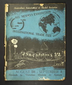
magazine, Australian Association of Model Societies, All Models Exhibition - International Trade Fair, 1955
... is a stylised depiction of the world globe linked to a gear by a drive... of the world globe linked to a gear by a drive chain. The lower part ...The exhibition was held in the Royal Exhibition Building from 25 August to 3 September 1955. The proceeds went to the the Mission.The magazine is one the many fundraising efforts from the Mission.A4-sized magazine of multiple pages. Front cover of magazine is in blue, white and black ink. At the top of the cover is a stylised depiction of the world globe linked to a gear by a drive chain. The lower part of the cover depicts a stylised abbreviated city and seaside scene. Inner pages are monochrome and detail ship model builds, with pictures.'1955 All models exhibition, International trade fair' 'August 25 - September 3' 'All proceeds to Missions to Seamen'trade fair, 1955, probus club, ship models, fundraising -
 Puffing Billy Railway
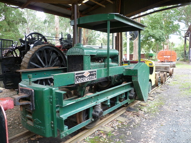
TACL - Erica State Sawmill Rail Tractor, 1928
... . Fordson engine coupled by a chain drive to the two axles...Rail Tractor with Fordson engine coupled by a chain drive... of victoria Rail Tractor with Fordson engine coupled by a chain drive ...TACL-Tractor Appliance Company Limited TACL rail tractors manufactured by Malcolm Moore of Port Melbourne Located in the Parishes of Moondarra and Telbit, Gippsland, the tramway terminated at Collins Siding on the Moe Walhalla 2'6"gauge branch of the Victorian Railways. Its construction by the Forests Commission of Victoria was to facilitate the extraction of timber from the Southern and Western slopes of Mount Erica and to replace the outlet tramways destroyed during the disastrous forest fires of February 1926. Tyers Valley Tramway The line, following the Eastern arm of the river, passed Ingrams Siding (7m.) to terminate at a forest area, known as "Ten Acre Block", 8m. 60c. from Collins Siding. The western branch of the line followed the Western Tyers Valley to Growlers Creek, 13m. 40c. from Collins Siding. THE T.A.C.L. TRACTORS at Tyers Valley tramway. On the 19th January 1928, T.A.C.L. locomotive, purchased from Tractor Appliance Co. Ltd. (Malcolm Moore), was delivered. This unit had a 20 h.p. Fordson engine coupled by a chain drive to the two axles, providing a tractive effort of approx. 2000lbs. Wheelbase was 5’ and weight was four tons. It was intended that the two tractor locomotives, working with the grade, would deliver timber from the branch lines to Tyers Junction, from which place it would be steam hauled out to the Collins Siding transfer point. Following a breakdown of the steam locomotive, haulage during the early months of 1928 was carried out by the T.A.C.L. unit, supplemented by the Nattrass, which was, by this time, becoming unreliable. During April 1928, after ensuring that no suitable locomotive was available in Australia, an order was placed with the Climax Manufacturing Co., U.S.A. for the supply of a geared locomotive. A second T.A.C.L. engine was purchased during May and, on the 27th, the local mill owners, having obtained running rights on the tramway, commenced haulage with the Harman. The three tractor units worked the branch lines and transported ballast, whilst the Harman hauled the timber to Collins Siding in rakes of eight trucks (56 tons). The weekly loading of the line for the first, second and third weeks were 54, 62 and 71 trucks respectively. info from : http://www.nmra.org.au/tyersvalley/Tyers-Tram.html Historic - Industrial Narrow gauge Railway - Timber working - Rail Tractor used by the the Forests Commission of Victoria on the Tyers Valley TramwayRail Tractor with Fordson engine coupled by a chain drive to the two axles - made of steel and wrought ironerica sawmill, puffing billy, tacl, rail tractor, tractor appliance co. ltd. (malcolm moore), industrial narrow gauge railway, tyers valley tramway, forests commission of victoria -
 Warracknabeal and District Historical Society
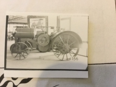
Tractor - International Harvester Titan 10-20hp, c.1915
... , enclosed transmission, chain drive, steel spoked wheels. Serial... are red. Magneto ignition, enclosed transmission, chain drive ...2 cylinder, petrol kerosene, 4 stroke farm tractor. Body is grey, wheels and pulley faces are red. Magneto ignition, enclosed transmission, chain drive, steel spoked wheels. Serial no: 56099 -
 Puffing Billy Railway
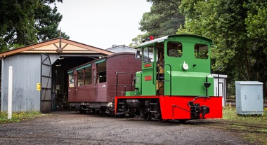
NRT1, Ruston & Hornsby Diesel Locomotive, 1951
... , they followed the radius of the drive chains, reducing the chances..., they followed the radius of the drive chains, reducing the chances ...NRT1 - Ruston & Hornsby Diesel Locomotive Built in 1951 to a gauge of 3', this Ruston diesel locomotive or rail tractor operated on the State Electricity Commission of Victoria’s Kiewa scheme. Some years later, it was regauged to 2'6" and was operated by the Melbourne & Metropolitan Board of Works. NRT1 is a Ruston & Hornsby diesel locomotive, built in England in 1951 to a gauge of 3 feet, and was initially employed by the State Electricity Commission of Victoria. It was later re-gauged to 2' 6" and ended it's working life in 1977 when it was transferred to Puffing Billy. In 1977, it was taken to the P.B.P.S. Steam Museum and stored until 1978 when it was taken to the Emerald Carriage Workshops. Later in 1983 it was returned to service as NRT1 following the V.R. classification procedure as a narrow-gauge rail tractor, but it had number plates installed and was painted Hawthorn green. It will eventually be painted the red of V.R. rail tractors with the number & class painted on in black. This type of locomotive was popular in many industrial locations, with their unique clutch-less 3 speed gearbox meaning the driver could control them whilst walking alongside, a bonus when shunting. Adjustable tie rods meant that as the axles moved on the springs, they followed the radius of the drive chains, reducing the chances of chain snatch LOCOMOTIVE DETAILS NRT class No. originally constructed : No. in service : 1 No. stored: Wheel arrangement : 0-4-0DM Roadworthy weight : 9T 3cwt. Maximum axle load : 4T 15cwt. Tractive effort (85%) : Length overall: 15' 6" Height overall: 10' Driving wheel diameter: 18" Date of manufacture: 1950 Manufacturer : Ruston Hornsby Place of manufacture: Lincoln, England Locomotive type : Diesel Mechanical Manufacturers classification : 48 DL Historic - Industrial narrow Gauge Railway - Ruston & Hornsby diesel locomotive used by State Electricity Commission of Victoria - NRT1 - Ruston & Hornsby Diesel Locomotive NRT1 - Ruston & Hornsby Diesel Locomotive made of steel NRT1 ruston & hornsby diesel locomotive, nrt1 diesel locomotive, nrt1, puffing billy -
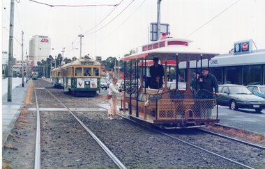
 Puffing Billy Railway
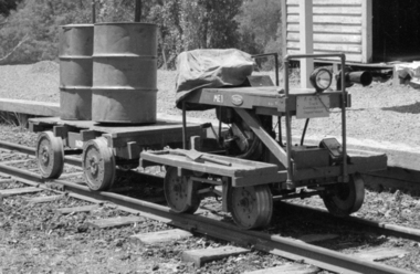
ME1, Victorian Railways 2'6" Gauge Trolly, 1958
... motorcycle engine to drive axle by roller chains through an 'Ariel... cylinder, 500 cc B.S.A. side valve motorcycle engine to drive axle ...It was constructed on a former Victorian Railways NKS type underframe and powered by a single cylinder, 500 cc B.S.A. side valve motorcycle engine to drive axle by roller chains through an 'Ariel Square Four' gearbox and has traveled on all four 2'6" narrow gauge lines that operated in the state of Victoria.Historic - Narrow Gauge Railway - Track Patrol Vehicle used by Puffing Billy Preservation Society and made from parts of a Victorian Railways track patrol vehicleMotorised small rectangular trolly made of wood and wrought iron ME1 P.B.P.S Track Construction Departmentme 1, trolley, victorian railway, 2'6" gauge, puffing billy, trolly -
 National Wool Museum
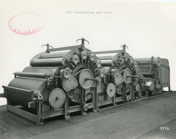
Photograph - Product Photograph, Two-Part Scribbler
... to Fancy Chain Drives, also feeder gearing.... by ‘V’ Belts. Note improved guarding to Fancy Chain Drives, also ...These are sales photographs for William Tatham Ltd. of Rochdale. These photographs are taken in the fitting shop at William Tatham Ltd. where final assembly would have taken place. The scribbler was the first part of a group of machines known collectively as the carding engine. The photographed machine was made by William Tatham Ltd, a textile engineering company based in Rochdale, UK. Established in 1866 Tatham developed innovative textile machinery and send their products to Australia and other countries around the world.A black and white photo of a Two-Part Scribbler in a landscape format.Front - top margin: For description see over. Front bottom right corner - 1076 Rear - Two-Part Scribbler, Semi-Continental Type with Patent Automatic Feed having Extended Hopper. Cylinders in this case are 50” diam. Doffers 36” diam. Drive to strippers and other parts by ‘V’ Belts. Note improved guarding to Fancy Chain Drives, also feeder gearing.textile machinery, tatham, wool manufacture, scribbler, carding -
 Melbourne Tram Museum
Photograph - Set of 3 Colour Print/s, Jeff Bounds, 11/03/1991 12:00:00 AM
... , side South Melbourne Depot after breaking chain drive in Park..., side South Melbourne Depot after breaking chain drive in Park ...Set of three colour prints of TMSV operating the motorised cable tram set and Royal Park tram 256 11/3/1991. The rear of each photograph gives the details. Photos by Jeff Bounds. 1 - "Cable tram dummy 593 being pushed along Kingsway along Kingsway, side South Melbourne Depot after breaking chain drive in Park St when turning from St Kilda Road." SW 5, 777, route 64 following along with another tram. 2 - "Cable tram set 593 and 171 in Swanston St, looking north to Franklin St, as TMSV Exhibit in Moomba Parade in conjunction with the Villa Maria Society." 3 - "Horse tram 256 waiting alongside tracks in Swanston St (north) for Met Tram service to allow for it to enter The Moomba Parade as part of The Met exhibit." 256 is alongside W6 964, running a South Melbourne Beach route 1, followed by a W7 St Kilda Beach, route 15. Has the Royal Women's Hospital in the background.All have above details written in ink, along with "TMSV" and "11/3/91".trams, tramways, tmsv, moomba, events, swanston st, kingsway, w6 class, cable trams, w7 class, sw5 class, route 1, route 15, route 64, w6 class, tram 593, tram 171, tram 593, tram 777, tram 964 -
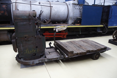 Puffing Billy Railway
Lister Auto Truck
... for petrol and a shorter oil tank. Engine and chain-drive lubrication... for petrol and a shorter oil tank. Engine and chain-drive lubrication ...The Lister Auto-Truck was a small monowheel tractor built for moving light loads around factories, railway yards and similar sites. They were built by R A Lister and Company of Dursley, Gloucestershire, well known for their range of small stationary engines The Auto-Truck was one of several monowheel tractors to appear in the 1920s and '30s, with the availability of small, reliable petrol engines, as developed for motorcycles and the stationary engines for which Lister were already known. These were tricycle vehicles, with the single leading wheel used for both drive and steering. Their simple construction carried most of the mechanism on this wheel as a single unit, the chassis with the trailing wheels being little more than a trailer for balance. Simplicity was a key feature. The engines were single-cylinder and air-cooled. Ignition was by magneto, rather than requiring a battery and electrical system. One of these designs was produced in the 1920s by George Grist of the Auto Mower Co., Norton St Philip, Somerset. The engine was a JAP 600 cc four-stroke air-cooled sidevalve, a typical small engine of the time. The Auto Mower Co. were Lister agents and when Lister heard of this 'Auto-Truck' they bought one for use in their own factory. It was used to carry heavy engine castings from the foundry to the machine shop. Lister customers saw them and there was such interest in wanting to buy them that Lister negotiated with Auto Mower to build them under licence. Although Lister were already well known for their small petrol stationary engines, these were heavy cast-iron engines with water hopper cooling and unsuitable for vehicle use. Lister remained with the JAP engine for the Auto-Truck. The Auto-Truck was designed for use in factories or other places with smooth surfaces of concrete or tarmac. This allowed the use of small solid-tyred wheels with only simple suspension, making the vehicle simple, cheap and lightweight. They had little ability on soft surfaces though and could even topple over if driven carelessly across slopes. Their design was a compromise between the top-heavy nature of the tall engine grouping above its wheel and a well thought-out chassis for stability. The bearing between them was a large diameter ring roller bearing, mounted at the lowest part of the chassis. This gave rigidity and stability, even after long wear. A ring of rolled channel girder was attached to the engine group and rollers on the chassis carried the load upon this. On early Auto-Trucks this bearing is set very low, in line with the chassis members, and is covered by thin steel plates. The front panel of the engine cover is distinctive with large ventilation holes and a Lister signature cut through it. Strangely this panel is made of thick cast iron, providing substantial weight high on the engine and only adding to its top heaviness. To improve visibility of moving vehicles in noisy factories, this panel was often painted white, the rest of the vehicle being Lister's usual brunswick green. The driver was seated on a Brooks bicycle saddle, which in recognition of the lack of vehicle suspension, was carried on the end of a cantilevered bar that acted as a leaf spring. A wide handlebar on the engine group was used for steering. A squeeze bar the width of this handlebar engaged the clutch. Controls included a hand throttle, a gear lever with two forward and one reverse gears, and a large handbrake lever. The engine unit rotated freely for a full 360° rotation. When used in reverse, the Auto-Truck could either be driven from the saddle, looking backwards over the driver's shoulder; or they could dismount, swivel the engine unit around and control it as a pedestrian-controlled truck from behind. Under the engine cover were two equal diameter tanks, a fuel tank for petrol and a shorter oil tank. Engine and chain-drive lubrication used a total-loss oil system, controlled by a small pump and needle valve. Info Ref: Lister Auto-Truck - Wikipedia https://en.wikipedia.org/wiki/Lister_Auto-TruckHistoric - Industrial monowheel tractor for moving light loads around factories, railway yards and similar sites.The Lister Auto-Truck - small monowheel tractor Made of steel with three wheels. Powered by a J.A.P single cylinder petrol motor which is Hand Cranked to start.Lister puffing billy, lister, lister auto truck, monowheel tractor -
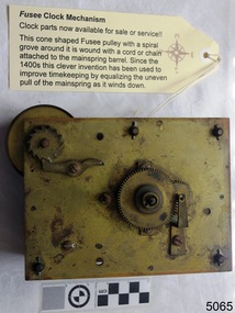 Flagstaff Hill Maritime Museum and Village
Machine - Fusee Clock Mechanism, early 20th Century
The origin of the fusee is not known. Many sources credit clockmaker Jacob Zech of Prague with inventing it around 1525. The earliest dated fusee clock was made by Zech in 1525, but the fusee appeared earlier, with the first spring-driven clocks in the 15th century. The idea probably did not originate with clockmakers, since the earliest known example is in a crossbow windlass shown in a 1405 military manuscript. Drawings from the 15th century by Filippo Brunelleschi and Leonardo da Vinci also show fusee mechanisms. The earliest existing clock with a fusee, also the earliest spring-powered clock, is the Burgunderuhr (Burgundy clock), a chamber clock whose iconography suggests that it was made for Phillipe the Good, Duke of Burgundy about 1430. Springs were first employed to power clocks in the 15th century, to make them smaller and portable.[1][5] These early spring-driven clocks were much less accurate than weight-driven clocks. Unlike a weight on a cord, which exerts a constant force to turn the clock's wheels, the force a spring exerts diminishes as the spring unwinds. The primitive verge and foliot timekeeping mechanism, used in all early clocks, was sensitive to changes in drive force. So early spring-driven clocks slowed down over their running period as the mainspring unwound. This problem is called lack of isochronism. Two solutions to this problem appeared with the first spring-driven clocks; the stack freed and the fusee. The stack freed, a crude cam compensator, added a lot of friction and was abandoned after less than a century. The fusee was a much more lasting idea. As the movement ran, the tapering shape of the fusee pulley continuously changed the mechanical advantage of the pull from the mainspring, compensating for the diminishing spring force. Clockmakers empirically discovered the correct shape for the fusee, which is not a simple cone but a hyperboloid. The first fusees were long and slender, but later ones have a squatter compact shape. Fusees became the standard method of getting constant force from a mainspring, used in most spring-wound clocks, and watches when they appeared in the 17th century. Around 1726 John Harrison added the maintaining power spring to the fusee to keep marine chronometers running during winding, and this was generally adopted. The fusee was a good mainspring compensator, but it was also expensive, difficult to adjust, and had other disadvantages: It was bulky and tall and made pocket watches unfashionably thick. If the mainspring broke and had to be replaced, a frequent occurrence with early mainsprings, the fusee had to be readjusted to the new spring. If the fusee chain broke, the force of the mainspring sent the end whipping about the inside of the clock, causing damage. The invention of the pendulum and the balance spring in the mid-17th century made clocks and watches much more isochronous, by making the timekeeping element a harmonic oscillator, with a natural "beat" resistant to change. The pendulum clock with an anchor escapement, invented in 1670, was sufficiently independent of drive force so that only a few had fusees. In pocketwatches, the verge escapement, which required a fusee, was gradually replaced by escapements which were less sensitive to changes in mainspring force: the cylinder and later the lever escapement. In 1760, Jean-Antoine Lépine dispensed with the fusee, inventing a going barrel to power the watch gear train directly. This contained a very long mainspring, of which only a few turns were used to power the watch. Accordingly, only a part of the mainspring's 'torque curve' was used, where the torque was approximately constant. In the 1780s, pursuing thinner watches, French watchmakers adopted the going barrel with the cylinder escapement. By 1850, the Swiss and American watchmaking industries employed the going barrel exclusively, aided by new methods of adjusting the balance spring so that it was isochronous. England continued to make the bulkier full plate fusee watches until about 1900. They were inexpensive models sold to the lower classes and were derisively called "turnips". After this, the only remaining use for the fusee was in marine chronometers, where the highest precision was needed, and bulk was less of a disadvantage until they became obsolete in the 1970s. Item is an example of clock mechanisms used until 1910 for many different styles of clocks and went out of fashion in the 1970s due to improvements in clock and watch making.Brass fusse clock movement, It has very heavy brass plates and wheels, high-count machined pinions, and a fusee. The mounting of the pendulum is missing and It has a recoil escapement. A fusee is a conical pulley driven through a chain by the spring barrel. As the spring runs down, the chain acts at a larger and larger radius on the conical pulley, equalising the driving torque. This keeps the rate of the clock more even over the whole run. It has motion work to drive an hour hand as well as a minute hand and the centre arbor is extended behind the back plate to drive some other mechanism.Inscription scratched on back"AM 40" flagstaff hill, warrnambool, shipwrecked-coast, flagstaff-hill, flagstaff-hill-maritime-museum, maritime-museum, shipwreck-coast, flagstaff-hill-maritime-village, clock mechanism, fusee mechanism, horology -
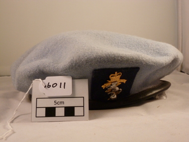 National Vietnam Veterans Museum (NVVM)
Headwear, RAAF Beret
Light blue wool felt beret with adjustable black ribbon headband. Pinned to the front is a gold/silver metal badge.Badge has Queen's crown, Insignia 'RAEME", horse chained to globeroyal australian air force, uniform, 161 reconnaissance flight -
 National Vietnam Veterans Museum (NVVM)
Functional Object, Optical Instruments
Periscopic Binocular Case - Green Has two latches to close lid,and chain.Binocular. Periscopic, A.F.V. Cased MK1/3 m L5 1240 - 66 - 052 - 4953 Case 053087A /AK & Sbinocular periscopic -
 National Vietnam Veterans Museum (NVVM)
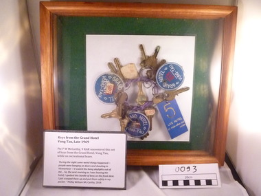
Souvenir - Keys, Grand Hotel, Vung Tau, framed, 1969 (Exact)
A set of Keys linked together on a purple chain. The chain has 3 keys tags of Grand Hotel and 1 tag of Lux Hotel. The set is kept in a wooden box with glass on the top side.Pte P W McCarthy 9RAR souvenired this set of keys from the Grand Hotel Vung tau while on recreational leave in late 1969.keys, vung tau -
 Bay Steamers Maritime Museum
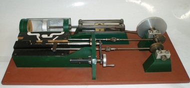
model steam engine
This model was found in the collection of Bay Steamers Maritime Museum. It is not knowt who created it but it is supposed that it was constructed to educate the many masters of the Wattle in the operation of a steam engine - a not so common mode of power these days. A Bay Steamers Maritime Museum examined the model in March 2012 and discovered that is was in poor repair. Using his existing knowledge, and with reference to some historic texts, he made some repairs and returned the model to working order. Here is his anaylsis of the situation as an excerpt from the Bay Steamers Maritime Museum newsletter Steamlines May 2012 "I was confronted with a model of a steam engine used years ago as a training aid for hopeful steam engineers. Already having a knowledge of steam operations, I considered a museum write-up for that model a ‘piece of cake’. However, on turning the model’s crankshaft, the valve timing seemed ‘out of kilter’ with the movement of the piston. Problem was that the two eccentrics on the crankshaft were not properly secured to it. Eventually I fastened the two eccentrics to the crankshaft where I felt that they should be and then realized that one of them had a chain-driven valve-timing device attached. This would be adjusted while an engine was running to achieve best performance and fuel economy whilst in operation by accurately controlling the period of time during which steam under pressure from the boiler would be admitted to the cylinder and give greater time for the steam to expand in the cylinder, move the piston and turn the crankshaft and thus, drive the attached apparatus. When the valves were correctly set up it was then possible to get the model to function properly.The model comprises a green section, which is the actual the model mounted on a brown painted board. There are two parts of the model, painted white representing the steam passages, and black representing the cast- iron portions of the cylinder-block casting, and of the main valve sliding between the cylinder a second sliding valve. Of the black portions, one slides back and forth being connected to a rod which is connected to an eccentric clamped to the crankshaft and is the nearer to the flywheel of two eccentrics. This eccentric is attached to the crankshaft at an angle of 90 degrees to the crank-pin attached to the flywheel. To operate the model simply turn the flywheel by means of the handle attached to its crank-pin. A second eccentric is also attached to the crankshaft, further away from the first eccentric, and it is adjusted to operate 90 degrees from the first eccentric (that is, 180 degrees from the crank-pin) A piston (painted silver) is located in a plastic cylinder and has a piston rod which passes through one end of the cylinder, (in actual practice a steam-proof gland seals the cylinder against loss of steam) terminating in a cross-head slide between four rails guiding it. From this cross-head, a connecting rod joins the piston-rod to the flywheel via the crank-pin attached to the flywheel which is part of the crankshaft. (In actual practice, a flywheel may not be used, particularly in a multi-cylinder engine.) The white portions of the model painted nearest to the cylinder represent the two steam ports cast into the main cylinder block, whilst one section painted in between those two represents the exhaust outlet (which may be connected to a condenser to conserve water, or to the open air). The main slide valve has three white-painted portions painted thereon. It has two white-painted marks representing the steam passages to the steam ports into the cylinder, and a third section in between the other two, being that part of the valve through which exhaust steam passes in line with the ports in the cylinder block. By rotating the flywheel, the operations of an engine will be observed as steam is admitted to the main valve via the gap between the two jaws of two moveable portions of a second sliding valve which is operated by the second eccentric attached to the crank-shaft. This eccentric is used to finely tune the valve timing of this model to obtain best running results of an engine. There are various methods used for reversing a steam engine. model compound steam engine, steam engine, model, crankshaft, valve, flywheel, wattle, engineer, eccentrics -
 National Vietnam Veterans Museum (NVVM)
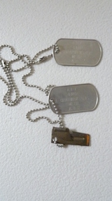
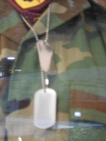
Equipment - Equipment, Army, Dog Tag
Metal dog tags with inscription on metal chain.The unlucky led by the unqualified to do the unecessary for the ungratefuldog tags -
 National Vietnam Veterans Museum (NVVM)
Uniform - Uniform, ARVN, Dog Tag
2 silver dog tags on a silver chain.dog tags, south vietnam army, major tu -
 National Vietnam Veterans Museum (NVVM)
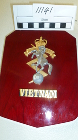
Plaque, R.A.E.M.E. Vietnam
Wooden shield with silver horse with chain from nect to a globe of the world on a gold lightning bolt. there is a crown on top, the letters "RAEME" and "vietnam" in goldRAEME Vietnamplaque, r.a.e.m.e. -
 National Vietnam Veterans Museum (NVVM)
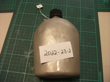
Equipment - Equipment, Army, Canteen Cover, 1962
Silver Metal Drink Canteen with black plastic screw top. Metal chain attached to lid and canteen body.canteen -
 National Vietnam Veterans Museum (NVVM)
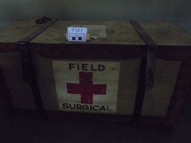
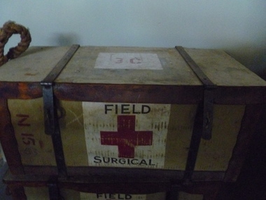
Equipment - Equipment, Army, Field Surgical Pack
Wicker trunk, canvas covered, plywood lid and base reinforced with leather on edges, rope carry handles, steel bindings with clasp and staple closures with 2 chains for transport. List of contents inside lid.IC on lid. FSP 1. FSP 1C. Filed surgical Red Cross on White background.field surgical pack, fsp -
 National Vietnam Veterans Museum (NVVM)
Equipment - Field surgical pack
Wicker trunk, canvas covered, plywood lid and base reinforced with leather on edges, ropes carry handles, steel bindings with clasp and staple closures with 2 chains for transport. Torn list of contents inside lid.Red cross on white background with "field surgical" on front FSP1 N15 53 30 3Cfsp, wicker trunk, field surgical pack -
 National Vietnam Veterans Museum (NVVM)
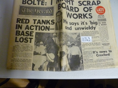
Newspaper, The Herald, 07-02-1968 (exact)
Headlines front page. "Red tanks in action - base lost" - an American Special forces Camp near Khe Sanh Four chain themselves to barracks. Melbourne to stop an intake of service men. Page 3 Now it's recruit Normie Rone Norman John 3793130newspaper, american special forces, khe sanh, battle of, 1968, normie rowe -
 National Vietnam Veterans Museum (NVVM)
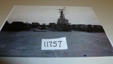
Photograph
Black and White photo taken on board HMAS Sydney of "conine Tower" with army vehicles chained to deck. June 1965. 1st tripphotograph, hmas sydney -
 National Vietnam Veterans Museum (NVVM)
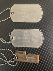
Equipment - Equipment, Army, Dog Tag
Metal set of dog tags worn by service person CP Chadwick attached to metal chain. Also a rusty bottle openerdog tags -
 Southern Sherbrooke Historical Society Inc.
Map, Dept of land s & Survey, Dandenong Ranges Area Sheet 28, Jan-56
Owned by David Walker, previously of Menzies Creek. Given by him to Rex Breen in 2001 for donation to society.Aerial survey map of parts of Gembrook, Monbulk and Naree Worran parishes (Victoria). Scale: 10 chains to 1 inch, contour interval 20 feet. Shows Menzies Creek and parts of Kallista, Clematis, Selby and Belgrave South. Ringwood D2C or 849D2C, Zone 7"16563" in pen on top left corner of reverse. -
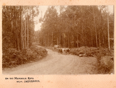 Southern Sherbrooke Historical Society Inc.
Photograph, On the Monbulk Road near Sherbrooke
Photo shows a team of cattle (bullocks, cows or steers) hauling a log down to the sawmill. A huge piece of timber is clearly seen chained to the dray. Heavy timber both sides of the road, most likely present-day Sherbrooke Forest. c.1920. -
 Otway Districts Historical Society
Photograph, Victorian Railways, Beech Forest: From 27 miles 16 chains looking north, c.1901, 1901
B/W. 168mm x 246mm. Colac - Beech Forest railway line. From the 27 mile 16 chains line (44.7 km) looking north, between Devitt Bros. Siding (44.1 km) and Ditchley (47 km). On an NA-class locomotive, six NQR wagons, and an open wagon there are workmen throughout. colac; beech forest; railways; devitt bros. siding; ditchley; loco na class -
 Otway Districts Historical Society
Photograph, Knox Collection, Pettit's Siding: A loader, teamster and their six-horse load, c.1920
Originally known as Smith's Siding, in November 1914 the siding was renamed "Pettits" following the sale of a nearby mill to the north. The sawn timber was initially carted out by bullock wagon but the mud and slush caused such difficulties that Pettits caused a thirty chain incline to be built from the mill to a tramway. The tramway connected the mill to the railway until 1924. An annual average of 2,450 tonnes of timber was despatched from the siding. No provision was made for passenger traffic. After ten years Pettit Brothers had cut out the area and moved on, abandoning the siding which was put out of commission on 23 September 1924. However, local residents, not wishing to suffer the loss of railway facilities, managed to have the siding reopened in February 1925 for goods and passengers. It was lightly patronised until all traffic ceased in 1936. B/W. Sam Knox, timber loader and tallyman, and George Pritchard, a teamster, resting at Pettit's Siding after delivering a six-horse-drawn load of timber to the Siding. Stacks of wood awaiting transport by rail are in the background.pettits siding; wyelangta; railways; smith's siding; sam knox; george pritchard; -
 Kew Historical Society Inc
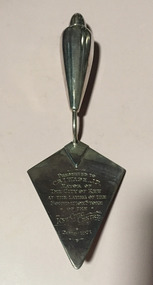
Ceremonial object, Unknown, Commemorative Trowel in Presentation Box, 1971, 1982
WADE, Ivan Mayor 1969-70, 1970-71 Ivan Wade grew up in Bendigo and Brunswick, one of eight children. After his marriage, he moved with his wife and young family to Kew in 1951. In 1959, he took a year’s sabbatical in 1959 to build a new family home for his wife and four children at 222 Cotham Road, Kew. He worked professionally in the Meat Industry, successfully building a small chain of retail butcher shops, and a meat exporting business. He worked for improvements in the Trade through involvement in the Meat and Allied Trades Federation, of which he was the first State, and then Federal President. He was to be awarded an OBE for his services to the Meat Industry in 1979. Having been a long-time member of Melbourne Lions Club, he helped start Chadstone Lions’ Club as an inaugural tenant of the Chadstone Shopping Centre in 1979. He was also a tireless worker for charity, making his home available for functions raising funds for local groups. His passion for the community led him to stand for Kew Council as a representative of College Ward. As a councillor, he was elected mayor for two terms. During his term of office, new Kew Municipal Offices were constructed in Cotham Road. An active worker for the Kew Elder Citizens Association, he was involved in the establishment of an Opportunity Shop in Walpole Street to raise funds for the development of a new Centre in High Street. The Opportunity Shop was used to train locally unemployed youth skills such as furniture repair. (GW)Silver presentation trowel associated with the opening of significant civic projects in the former City of Kew.Commemorative, inscribed silver-plated presentation trowel given by the City of Kew to the Mayor, Cr Ivan Wade, on the occasion of the laying of the foundation stone of the new Kew Civic Centre on the corner of Cotham Road and Charles Street, now part of Trinity Grammar School. The silver trowel was presented in a black leather case lined with blue velvet. The trowel was to be used a second time in 1982 when Cr Wade and his wife laid the foundation stone of Hamer Court. The trowel was later donated to Kew Historical Society Inc by Gwlad Wade, the wife of Cr Ivan Wade, on 20 August 2000. Front: "Presented to Cr Wade J.P. / Mayor of / the City of Kew / at the laying of the / foundation stone / of the / Kew Civic Centre /20-8-1971." Reverse: This trowel was also used / by / Cr Ivan Wade OBE JP & Mrs Gwlad Wade / at the laying / of the foundation stone / of / "Hamer Court" / Hostel for the Aged / 22nd August 1982"cr ivan wade, hamer court, commemorative trowels, kew civic offices, city of kew 1860-1993 -
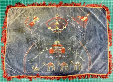 Kew Historical Society Inc
Textile - Souvenir Textile, Souvenir of Palestine, c1939-45
Souvenir probably bought by an Australian soldier in the 2nd A.I.F., and brought back to Australia as a souvenir.Rectangular blue faded to grey velveteen water damaged textile with a plain white cotton backing with a red fringe. The front of the textile is embroidered in red, yellow, blue and white chain stitch. It shows two palms flanking the Mosque of Omar lower centre with three camels and a man on a horse below, Rachel's Tomb with tree upper left and David's Tower upper right."Souvenir of Palestine"; "Rachels tomb"; "Mosque of Omar"; "David's Tower"second world war 1939-1945, table cover, palestine, 2nd aif, souvenir, textiles - embroideries, wwi