Showing 40 items matching "fuel valves"
-
 Moorabbin Air Museum
Manual (Item) - Aircraft Accessories - Fuel Valves pumps, oil coolers
... Aircraft Accessories - Fuel Valves pumps, oil coolers,...Aircraft Accessories - Fuel Valves pumps, oil coolers,...Moorabbin Air Museum Moorabbin Airport 12 First Street Moorabbin melbourne Aircraft Accessories - Fuel Valves pumps, oil coolers, Manual Aircraft Accessories - Fuel Valves pumps, oil coolers, ... -
Moorabbin Air Museum
Document - Test Procedure Functional Test Procedure for Swing Check Valves, Fuel System, Various, as Listed, Commonwealth Aircraft Corporation
... Test Procedure Functional Test Procedure for Swing Check Valves, Fuel System, Various, as Listed...Commonwealth Aircraft Corporation Document Test Procedure Functional Test Procedure for Swing Check Valves, Fuel System, Various, as Listed ... -
Moorabbin Air Museum
Manual - Holley Aircraft Carburettors, Holley Aircraft Carburettors Instruction Manual Third Edition
... ...Fuel valves...Moorabbin Air Museum Moorabbin Airport 12 First Street Moorabbin melbourne Holley Aircraft Carburetors Accelerating pump CAM Carburetor Clearance chart & diagra Compensator jet/needle/seat/spring/unit Diaphragm unit & vents End blocks Fixtures & tools Fuel valves Inlets Limits Mixture control Nozzle bar Overhaul sheets Primers Power mixture valve Stabilizer valve Test stand Throttles Vapor separator Vent ring Venturi Instructions on servicing & maintenance of Holley aircraft carburetors, circa 1941 Appears to be a duplicate item Holley Aircraft Carburettors Instruction Manual Third Edition Manual Holley Aircraft Carburettors ...Instructions on servicing & maintenance of Holley aircraft carburetors, circa 1941Appears to be a duplicate itemnon-fictionInstructions on servicing & maintenance of Holley aircraft carburetors, circa 1941accelerating pump, cam, carburetor, clearance chart & diagra, compensator jet/needle/seat/spring/unit, diaphragm unit & vents, end blocks, fixtures & tools, fuel valves, inlets, limits, mixture control, nozzle bar, overhaul sheets, primers, power mixture valve, stabilizer valve, test stand, throttles, vapor separator, vent ring, venturi -
Moorabbin Air Museum
Document (item) - Mirage 111O correspondence re altitude testing of fuel bypass valve for the ATAR 9C engine, Mirage correspondence - ATAR Project - File 7
... Mirage 111O correspondence re altitude testing of fuel bypass valve for the ATAR 9C engine...Letters between SNECMA and CAC re altitude testing of fuel bypass valve for the ATAR engine...Letters between SNECMA and CAC re altitude testing of fuel bypass valve for the ATAR engine Mirage correspondence - ATAR Project - File 7 Document Mirage 111O correspondence re altitude testing of fuel bypass valve for the ATAR 9C engine ...Letters between SNECMA and CAC re altitude testing of fuel bypass valve for the ATAR engine -
 Moorabbin Air Museum
Manual (Item) - (SP) AAP 7271.048-3 727.149 Part Model or Type No B99-26-203 and B99-26-204 Valve, Fuel Cut Out Type 16
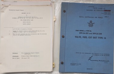
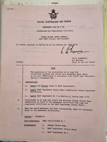
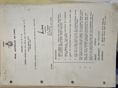
... (SP) AAP 7271.048-3 727.149 Part Model or Type No B99-26-203 and B99-26-204 Valve, Fuel Cut Out Type 16......valve and fuel cut out type 16...A manual for part model or type no B99-26-203 and B99-26-204 valve, fuel cut out type 16....A manual for part model or type no B99-26-203 and B99-26-204 valve, fuel cut out type 16. Royal Australian Air Force valve and fuel cut out type 16 Australian Air Publication Manual (SP) AAP 7271.048-3 727.149 Part Model or Type No B99-26-203 and B99-26-204 Valve, Fuel Cut Out Type 16 ...Released around 1970 by the Royal Australian Air Force. A manual for part model or type no B99-26-203 and B99-26-204 valve, fuel cut out type 16.royal australian air force, valve and fuel cut out type 16, australian air publication -
 Moorabbin Air Museum
Manual (Item) - (SP) AAP 7276.019-3 Single Barrel Servo Control Jack Type 103-35-1 Amendment List 6
... ...valve and fuel cut out type 16...A manual for part model or type no B99-26-203 and B99-26-204 valve, fuel cut out type 16....A manual for part model or type no B99-26-203 and B99-26-204 valve, fuel cut out type 16. Royal Australian Air Force valve and fuel cut out type 16 Australian Air Publication Manual (SP) AAP 7276.019-3 Single Barrel Servo Control Jack Type 103-35-1 Amendment List 6 ...Released around 1970 by the Royal Australian Air Force. A manual for part model or type no B99-26-203 and B99-26-204 valve, fuel cut out type 16.royal australian air force, valve and fuel cut out type 16, australian air publication -
 Moorabbin Air Museum
Manual (Item) - (SP) AAP 7276.019-3MB1 to B2 Single Barrel Servo Control Jack Amendment List 12
... ...valve and fuel cut out type 16...A manual for part model or type no B99-26-203 and B99-26-204 valve, fuel cut out type 16....A manual for part model or type no B99-26-203 and B99-26-204 valve, fuel cut out type 16. Royal Australian Air Force valve and fuel cut out type 16 Australian Air Publication Manual (SP) AAP 7276.019-3MB1 to B2 Single Barrel Servo Control Jack Amendment List 12 ...Released around 1970 by the Royal Australian Air Force. A manual for part model or type no B99-26-203 and B99-26-204 valve, fuel cut out type 16.royal australian air force, valve and fuel cut out type 16, australian air publication -
 Kiewa Valley Historical Society
Iron Hand Kerosene, mid to late 1900s
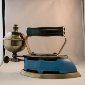
... The bowl has an air valve and inlet for pressurised air intake (hand pump) On the bottom rear of the fuel bowl there is a screw regulated fuel pump. ...The bowl has an air valve and inlet for pressurised air intake (hand pump) On the bottom rear of the fuel bowl there is a screw regulated fuel pump. ...The 1950's saw a revolution in small appliances for use in the average household. This hand held self heating(kerosene) iron was introduced as a time saving and more convenient iron for pressing clothes and other cloth fabrics. It replaced irons needing a separate fire source to heat the ironing plate. These irons continued to be in service, even when electricity was available in cities and larger rural towns (domestic electric steam irons were invented in 1938). This item was used before and during the electricity supplies available from the Kiewa Hydro Electricity Scheme. These irons remained in use within regional rural areas that had limited or unreliable electrical reticulation.In the 1950s and later the Kiewa Valley was still a relatively isolated region which was home to rural properties and small settlements. The availability of electricity and or the financial means to afford new types of electric hand irons ensured that older and sometimes less efficient ironing remained for an extended period covering the 1960s to 1970s. Kerosene products, such as this kerosene iron was a cheaper method for farm based domestic and other rural activities requiring a heat source. The use of kerosene as a heat/light source was able to be supplied in bulk and able to be used when floods severed vital roads into this region. The supply of electricity was in summer time subject to interruption from bush fire damaged wooden poles carrying the electrical cables. Self sufficiency by rural populations was the backbone of survival and the ability to store energy sources "on the farm" was a prerequisite of isolated regions, such as the Kiewa Valley, circa 1950s.This Coleman kerosene iron has a solid steel chrome plated(press) base with a painted (blue) wooden handle. The handle is stud fastened onto an oblong shaped rolled steel handle frame and screwed (two screws) onto the base plate. Both the heating plate and the top securing plate are shaped similar to a river boat. The main housing enclosing the heating element is enamel coated(blue in colour) steel and has a half hole for lighting the kerosene at the rear end. Behind the handle and protruding upwards is a stainless steel fully enclosed container (bowl shaped) for the main supply of kerosene to the burner or generator(enclosed within the main body of the iron. The bowl has an air valve and inlet for pressurised air intake (hand pump) On the bottom rear of the fuel bowl there is a screw regulated fuel pump. The fuel heated base plate provides the heat for this advertised "self heating iron(instant lighting). See KVHS 0347B- Instruction sheet; KVHS 0347C- Wrench; and KVHS 0347D Fuel can.Stamped on the base plate of the handle, front region "COLEMAN LAMP & STOVE CO." below this "WICHITA KAN" below this"TORONTO CAN". In the middle of the handle base and in larger print "COLEMAN Instant-Lite" At the rear location in large print "MODEL 4" in smaller print below "MADE IN U.S.A." below this "PAT#1718473"household appliances, alternative non electrical ironing appliances, domestic appliances, kerosene appliances -
4th/19th Prince of Wales's Light Horse Regiment Unit History Room
Photograph, Australian Army Public Relations, "Shorty" Shaw from Reservoir, Bandsman, 1976
... A black & white photograph of a soldier operating a valve on a fuel bladder. There are tents in the background. ...Stamp of Army Public Relations YOR 76 137 A black & white photograph of a soldier operating a valve on a fuel bladder. There are tents in the background. ...A black & white photograph of a soldier operating a valve on a fuel bladder. There are tents in the background. On back: "Shorty" Shaw from Reservoir, Bandsman. Stamp of Army Public Relations YOR 76 137photo, band, shaw -
 Bay Steamers Maritime Museum
model steam engine
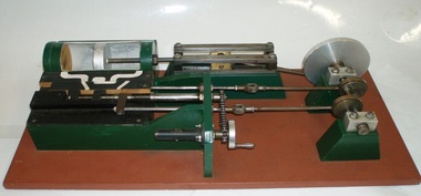
... valve-timing device attached. This would be adjusted while an engine was running to achieve best performance and fuel economy whilst in operation by accurately controlling the period of time during which steam under pressure from the boiler would be admitted to the cylinder and give greater time for the steam to expand in the cylinder, move the piston and turn the crankshaft and thus, drive the attached apparatus. ...valve-timing device attached. This would be adjusted while an engine was running to achieve best performance and fuel economy whilst in operation by accurately controlling the period of time during which steam under pressure from the boiler would be admitted to the cylinder and give greater time for the steam to expand in the cylinder, move the piston and turn the crankshaft and thus, drive the attached apparatus. ...This model was found in the collection of Bay Steamers Maritime Museum. It is not knowt who created it but it is supposed that it was constructed to educate the many masters of the Wattle in the operation of a steam engine - a not so common mode of power these days. A Bay Steamers Maritime Museum examined the model in March 2012 and discovered that is was in poor repair. Using his existing knowledge, and with reference to some historic texts, he made some repairs and returned the model to working order. Here is his anaylsis of the situation as an excerpt from the Bay Steamers Maritime Museum newsletter Steamlines May 2012 "I was confronted with a model of a steam engine used years ago as a training aid for hopeful steam engineers. Already having a knowledge of steam operations, I considered a museum write-up for that model a ‘piece of cake’. However, on turning the model’s crankshaft, the valve timing seemed ‘out of kilter’ with the movement of the piston. Problem was that the two eccentrics on the crankshaft were not properly secured to it. Eventually I fastened the two eccentrics to the crankshaft where I felt that they should be and then realized that one of them had a chain-driven valve-timing device attached. This would be adjusted while an engine was running to achieve best performance and fuel economy whilst in operation by accurately controlling the period of time during which steam under pressure from the boiler would be admitted to the cylinder and give greater time for the steam to expand in the cylinder, move the piston and turn the crankshaft and thus, drive the attached apparatus. When the valves were correctly set up it was then possible to get the model to function properly.The model comprises a green section, which is the actual the model mounted on a brown painted board. There are two parts of the model, painted white representing the steam passages, and black representing the cast- iron portions of the cylinder-block casting, and of the main valve sliding between the cylinder a second sliding valve. Of the black portions, one slides back and forth being connected to a rod which is connected to an eccentric clamped to the crankshaft and is the nearer to the flywheel of two eccentrics. This eccentric is attached to the crankshaft at an angle of 90 degrees to the crank-pin attached to the flywheel. To operate the model simply turn the flywheel by means of the handle attached to its crank-pin. A second eccentric is also attached to the crankshaft, further away from the first eccentric, and it is adjusted to operate 90 degrees from the first eccentric (that is, 180 degrees from the crank-pin) A piston (painted silver) is located in a plastic cylinder and has a piston rod which passes through one end of the cylinder, (in actual practice a steam-proof gland seals the cylinder against loss of steam) terminating in a cross-head slide between four rails guiding it. From this cross-head, a connecting rod joins the piston-rod to the flywheel via the crank-pin attached to the flywheel which is part of the crankshaft. (In actual practice, a flywheel may not be used, particularly in a multi-cylinder engine.) The white portions of the model painted nearest to the cylinder represent the two steam ports cast into the main cylinder block, whilst one section painted in between those two represents the exhaust outlet (which may be connected to a condenser to conserve water, or to the open air). The main slide valve has three white-painted portions painted thereon. It has two white-painted marks representing the steam passages to the steam ports into the cylinder, and a third section in between the other two, being that part of the valve through which exhaust steam passes in line with the ports in the cylinder block. By rotating the flywheel, the operations of an engine will be observed as steam is admitted to the main valve via the gap between the two jaws of two moveable portions of a second sliding valve which is operated by the second eccentric attached to the crank-shaft. This eccentric is used to finely tune the valve timing of this model to obtain best running results of an engine. There are various methods used for reversing a steam engine. model compound steam engine, steam engine, model, crankshaft, valve, flywheel, wattle, engineer, eccentrics -
 Bendigo Historical Society Inc.
Photograph - CASTLEMAINE GAS COMPANY COLLECTION: PHOTO BUILDINGS
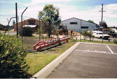
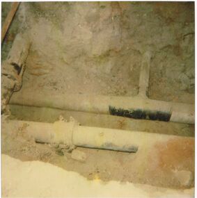
... History House 11 Mackenzie Street Bendigo goldfields ORGANISATION Industry gas and fuel Kodak Photo of 2 factories and a couple of vehicles. A truck and a panel van, A red pipe with several valves on top can be seen at the centre of the photo. ...Photo of 2 factories and a couple of vehicles. A truck and a panel van, A red pipe with several valves on top can be seen at the centre of the photo. The pipe is near what looks like a fenced car park.Kodakorganisation, industry, gas and fuel -
 Bendigo Historical Society Inc.
Photograph - CASTLEMAINE GAS COMPANY COLLECTION: PHOTO MAIN GAS VALVE
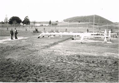
... History House 11 Mackenzie Street Bendigo goldfields ORGANISATION Industry gas and fuel Date and Location Unknown - Main Gas Valves in a Fenced off Paddock Photograph CASTLEMAINE GAS COMPANY COLLECTION: PHOTO MAIN GAS VALVE ...Date and Location Unknown - Main Gas Valves in a Fenced off Paddockorganisation, industry, gas and fuel -
 Flagstaff Hill Maritime Museum and Village
Equipment - Pump, circa 1930's - 1940's
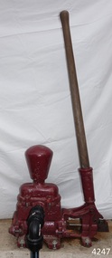
... valve opens and the pressure within the pump forces the water out of the pump through the exit pipe. The limitation of this type of pump is that it can only raise the water a maximum of about 7 metres from beneath the ground and yields 24-26 Litres per minute. This type of pump could be used for many purposes such as pumping water or fuel...valve opens and the pressure within the pump forces the water out of the pump through the exit pipe. The limitation of this type of pump is that it can only raise the water a maximum of about 7 metres from beneath the ground and yields 24-26 Litres per minute. This type of pump could be used for many purposes such as pumping water or fuel ...This pump is an Ajax Type L2 Series A model, made and sold by McPherson’s Pty Ltd of Melbourne circa 1930’s to 1940’s, is a mechanical, hand operated, constant flow pressure pump. It would have been used to pump fluids from one area to another, for example from a dam to a tank or used as a bilge pump on a small vessel, mounted on the vessel’s bulkhead, floor or deck. This type of hand pump is sometimes called a ‘Reciprocating Suction Pump’. It has a mechanical pumping action of the lever moves the piston inside the pump up and down. The water is lifted from below the pump through the inlet pipe and into the pump’s cylinder. This action causes the lower valve to close and the piston’s valve opens and the pressure within the pump forces the water out of the pump through the exit pipe. The limitation of this type of pump is that it can only raise the water a maximum of about 7 metres from beneath the ground and yields 24-26 Litres per minute. This type of pump could be used for many purposes such as pumping water or fuel. McPherson’s 1940’s advertisement proclaims “For all jobs on the land – irrigation, spraying, tank, plumbing, fire-fighting – there’s a suitable “Ajax” pump. Send us the details of you pumping problem. Our Expert’s advice will help you choose the right pump – the one that will give you most years of PROFITABLE PUMPING.” (The Australasian (Melbourne) Sat. 26th October 1940.) McPherson’s Pty Ltd, the manufacturer, advertised a similar pump to this one in The Australasian (Melbourne) in 1936, calling it the Ajax Double Acting Hand Pump. In 1942 another advertisement advised that a representative for a fire-fighting equipment supplier was visiting the western district of Victoria. The company could now supply double-action two-spray Ajax pumps at lower prices than similar pumps the district had recently purchased from Adelaide. McPHERSON’S FOUNDER and COMPANY TIMELINE 1860 – Thomas McPherson, a Scottish immigrant (c. 1853 ), founded McPherson’s in Melbourne, supplying pig iron (lead ingots imported as ballast in ships) to local manufacturers. 1882 – Thomas McPherson established a warehouse in Collins St Melbourne and included tools, steam fittings and machinery in his wares. The business expanded to include steam saw mills and became known as Thomas McPherson and Sons (William Murray and Edward). 1888 – Thomas passed away and his sons inherited the business. In 1896 William Murray became the sole proprietor after his brother Edward’s death. 1900 – The firm expanded, establishing Acme Bolt Company to manufacture nuts and bolts. 1912 – McPhersons Pty Ltd established a machinery warehouse and showroom in 554-556 Collins St Melbourne. McPherson’s went on to establish branches in Sydney (1911), Adelaide (1921) and Perth (1930) 1917 - McPherson’s supplied ‘dog spikes’ for the transcontinental railway, running from Eastern to Western Australia. 1918 – A tool works set up in Kensington, Melbourne, manufacturing Macson lathes and made machine tools that previously had to be imported. 1924 – The Bolt Works was transferred to a new building in Melbourne. McPhersons began making pumps. 1929 – McPherson retired. His son (Sir) William Edward McPherson (known as ‘WE’), was born in Hawthorne, Melbourne, in 1898. After his education he began work in his father’s Melbourne hardware and machinery business He took over as governing director when his father retired. 1929-1932 – McPherson’s supplied thousands of tons of rivets from its Richmond (Melbourne) Bolt Works for the construction of the Sydney Harbour Bridge. 1936 – McPherson’s Pty Ltd is advertising Ajax Pumps in newspapers 1934 – McPhersons purchased the property adjoining the warehouse in Collins Street, and during 1935-1936 built a new office and showrooms on the site of 546-445 Collins St. 1939 - McPherson’s acquired the Tool Equipment Co. Pty. Ltd and Associated Machine Tools Australia Pty Ltd was formed to separate McPherson’s machine-tool manufacturing and merchandising interests. 1939 – Ajax Pump Works, a foundry and pump manufacturing plant, was established in Tottenham, Melbourne, and the Ajax Bolt and Rivet Co Pty Ltd began manufacturing in New Zealand. 1944 - McPherson’s became a public company, McPherson’s Ltd. 1948 - The Ajax Pump Foundry opened at Kyneton, Victoria and in the post war years it grew to became a large manufacturer. 1980’s – Ajax Pumps brochure lists the address as 6 Buckhurst St, South Melbourne, Vic 3205 with the Telephone number 03 669 3588 1988 - Ajax Pumps acquired the Forrers Company, which was established in 1921. Manufacturing in Ipswich, Queensland, specialising in submersible sewage pumps. 1991 – KSB Ajax was formed, bringing together the companies KSB and Ajax Pumps 1993 – Manufacturing was moved to state-of-the-art premises in Tottenham, Victoria 2001 - The Forrers facility was moved to Tottenham. 2007 - Company name KSB Ajax Pumps was changed to KSB Australia Pty Ltd. 2009 - KSB Australia opened a branch in Townsville, Queensland. 2011 - KSB Australia moved to its dedicated Water and Waste Water Competence Centre in Bundamba, Queensland. DISPLAY OF THIS AJAX PUMP This pump was installed at Flagstaff Hill Maritime Village as part of a working display in the village by the Friends of Flagstaff Hill, in acknowledgement of the dedicated involvement of one of its long serving members, Bob Crossman. The display was officially opened 31st March 2018 and incorporates a restored Furphy Tank and Water Pipe Stand. The pump is used to draw water from the lake, through the water stand pipe and into the reconditioned Furphy Tank. This Ajax pump made by McPherson’s Pty Ltd is significant for its association with McPherson’s, a prominent manufacturer of hardware in Victoria. McPherson’s is famous for supplying ‘dog-spikes’ for the transcontinental railway (eastern to western Australia, 1917) and rivets for the Sydney Harbour Bridge (1929-1932). The Ajax pump is also of significance because of its association with McPherson’s Governing Director (Sir) William McPherson, former premier and treasurer in Victoria 1928-1929. The former McPherson’s Pty Ltd building in Collins Street Melbourne is now on the Victorian Heritage Register VHR H0942 This pump is representative of mechanical pumps popular in the early to mid-1900’s and still used today. Hand operated pressure pump, double acting. Cast metal case, painted red, with steel hose attachments and long metal lever. Pump is bolted to wooden plank. Model of pump is AJAX, Type L2, Series A pump. Embossed on lower section of pump "L2 - 10", "L2 - -1", "AJAX" “(?) –2-1” Embossed on lower handle “3-7” “L – 4” Embossed on attached plate “FOR SPARE PARTS / TYPE L2 / SERIES A / PUMP ASSEMBLED BY T R” Manufactured by McPherson’s Pty Ltd of Melbourne circa 1930’s - 1940’s.flagstaff hill, warrnambool, flagstaff hill maritime museum, shipwreck coast, flagstaff hill maritime village, great ocean road, ajax pump works tottenham melbourne, ajax pump factory kyneton, william edward mcpherson, thomas mcpherson of melbourne, mcpherson’s pty ltd melbourne, acme bolt company, tool equipment co. pty. ltd, associated machine tools australia pty ltd, ajax bolt and rivet co. pty ltd new zealand, forrers company ipswich queensland, ksb ajax pumps, ksb australia pty ltd, macson lathes, tool manufacturer early to mid- 20th century, ajax double acting hand pump, ajax type l2 series a pump, qisjax pumps, water pump 1940’s, fuel pump 1940’s, hand operated constant flow pressure pump, reciprocating suction pump, agricultural hand pump, plumber’s hand pump, portable hand pump -
Glenelg Shire Council Cultural Collection
Photograph - Photograph - oil tanks, n.d
... Glenelg Shire Council Cultural Collection History House Cliff Street Portland great-ocean-road Port of Portland Authority Archives Port of Portland Archives fuel containers Black and white photograph of a man adjusting clamp on pipe at base of tank. Another tank with pipes and dials and valves in background. ...Port of Portland Authority Archivesport of portland archives, fuel containers -
Ballarat Tramway Museum
Document - Instruction, "Jelbart Road Roller"
... Instruction of starting, adjustments, fuel, speed, operation, maintenance, air valve timing, and lubrication of the SEC Jelbart Road Roller. ...Ballarat Tramway Museum South Gardens Reserve Wendouree Parade Ballarat Ballarat goldfields Instruction of starting, adjustments, fuel, speed, operation, maintenance, air valve timing, and lubrication of the SEC Jelbart Road Roller. ...Instruction of starting, adjustments, fuel, speed, operation, maintenance, air valve timing, and lubrication of the SEC Jelbart Road Roller. This item is now at the Bylands Tramway Museum.Yields information about the operation of the SECV Ballarat Road roller supplied by Jelbart.Four quarto sheets, stapled in top left hand corner.secv, ballarat, jelbart, instructions, road roller -
 Bendigo Historical Society Inc.
Photograph - CASTLEMAINE GAS COMPANY COLLECTION: PHOTO 200 HP S7 OUTLET, 09/04/1991
... ORGANISATION Industry gas and fuel Polaroid 200 HP S7 100 Outlet Note no Tee no Valve - Iso LP Cast iron DNR Tie in Point - Eaglehawk Road Kiosk - 09/04/1991 Photograph CASTLEMAINE GAS COMPANY COLLECTION: PHOTO 200 HP S7 OUTLET ...200 HP S7 100 Outlet Note no Tee no Valve - Iso LP Cast iron DNR Tie in Point - Eaglehawk Road Kiosk - 09/04/1991Polaroidorganisation, industry, gas and fuel -
 Royal Australasian College of Surgeons Museum and Archives
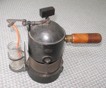
Tool - LIster's Carbolic Spray, circa 1930's
... Fuel for the wick is carried in a tank at the base. Valves regulate the pressure of the steam, and the nozzle is adjustable. ...Fuel for the wick is carried in a tank at the base. Valves regulate the pressure of the steam, and the nozzle is adjustable. ...The College’s spray was one of the first pieces of surgical memorabilia to come into the possession of the College. It had been used in the Listerian wards of the Glasgow Royal Infirmary, and was presented , along with some other artefacts, by James Hogarth Pringle in 1930. Joseph Lister (1827-1912) is known as a father of modern surgery. His methods of preventing infection were controversial in their time, but are today recognized as a major advance in the practice of surgery. Lister’s life and achievements are too well known to be recounted here. The definitive biography was written by his nephew, Sir Rickman Godlee (PRCSE 1911-13), and published in 1917. Douglas Guthrie gives an glimpse of Lister at work: “...He never wore a white gown and frequently did not even remove his coat, but simply rolled back his sleeves and turned up his coat collar to protect his starched collar from the cloud of carbolic spray in which he operated...” From advances in bacteriology, and discoveries by Robert Koch and others, it became increasingly evident that airborne bacteria were not a significant contributor to sepsis in surgical wounds. They also demonstrated that the body had its own defences against invading organisms, which were seriously compromised by the effects of the carbolic spray. Gradually the use of the spray was curtailed, Lister himself finally abandoning it in 1887. Lister performed the first antiseptic operation, the dressing and splintage of a compound fracture of the lower leg, in 1865. At this time he used carbolic solution by application, and dressings soaked in the solution. The spray was developed later, after many different methods, including carbolic and linseed oil putty, had been tried in order to reduce the harmful side-effects of undiluted carbolic acid. The steam spray was developed in 1869, and announced to the medical world in 1871. Lister’s purpose in adopting the spray was to kill airborne bacteria in the vicinity of the operation before they could reach the patient. It came to be used all over the world for many years. However, it had serious disadvantages, which even Lister acknowledged. The principal problem was the inhalation of carbolic vapour by everyone in the vicinity, including the patient and the operator. In addition, if the patient had been anæsthetized using chloroform, the gas lights decomposed the vapour into chlorine gas, making any procedure an ordeal of endurance.The spray consists of a steam boiler heated by a wick, a nozzle for the steam to escape, and a glass jar for the carbolic solution. Fuel for the wick is carried in a tank at the base. Valves regulate the pressure of the steam, and the nozzle is adjustable. The boiler is made of cast iron, the fittings are brass, and the handles are of wood. Empty, the apparatus weighs 8 lbs (3.2 kg). lister, carbolic spray, antiseptic -
 Puffing Billy Railway
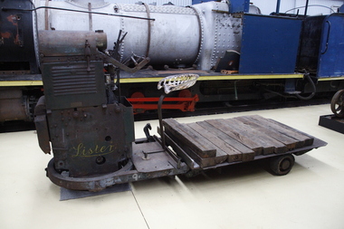
Lister Auto Truck
... fuel tank for petrol and a shorter oil tank. Engine and chain-drive lubrication used a total-loss oil system, controlled by a small pump and needle valve. ...fuel tank for petrol and a shorter oil tank. Engine and chain-drive lubrication used a total-loss oil system, controlled by a small pump and needle valve. ...The Lister Auto-Truck was a small monowheel tractor built for moving light loads around factories, railway yards and similar sites. They were built by R A Lister and Company of Dursley, Gloucestershire, well known for their range of small stationary engines The Auto-Truck was one of several monowheel tractors to appear in the 1920s and '30s, with the availability of small, reliable petrol engines, as developed for motorcycles and the stationary engines for which Lister were already known. These were tricycle vehicles, with the single leading wheel used for both drive and steering. Their simple construction carried most of the mechanism on this wheel as a single unit, the chassis with the trailing wheels being little more than a trailer for balance. Simplicity was a key feature. The engines were single-cylinder and air-cooled. Ignition was by magneto, rather than requiring a battery and electrical system. One of these designs was produced in the 1920s by George Grist of the Auto Mower Co., Norton St Philip, Somerset. The engine was a JAP 600 cc four-stroke air-cooled sidevalve, a typical small engine of the time. The Auto Mower Co. were Lister agents and when Lister heard of this 'Auto-Truck' they bought one for use in their own factory. It was used to carry heavy engine castings from the foundry to the machine shop. Lister customers saw them and there was such interest in wanting to buy them that Lister negotiated with Auto Mower to build them under licence. Although Lister were already well known for their small petrol stationary engines, these were heavy cast-iron engines with water hopper cooling and unsuitable for vehicle use. Lister remained with the JAP engine for the Auto-Truck. The Auto-Truck was designed for use in factories or other places with smooth surfaces of concrete or tarmac. This allowed the use of small solid-tyred wheels with only simple suspension, making the vehicle simple, cheap and lightweight. They had little ability on soft surfaces though and could even topple over if driven carelessly across slopes. Their design was a compromise between the top-heavy nature of the tall engine grouping above its wheel and a well thought-out chassis for stability. The bearing between them was a large diameter ring roller bearing, mounted at the lowest part of the chassis. This gave rigidity and stability, even after long wear. A ring of rolled channel girder was attached to the engine group and rollers on the chassis carried the load upon this. On early Auto-Trucks this bearing is set very low, in line with the chassis members, and is covered by thin steel plates. The front panel of the engine cover is distinctive with large ventilation holes and a Lister signature cut through it. Strangely this panel is made of thick cast iron, providing substantial weight high on the engine and only adding to its top heaviness. To improve visibility of moving vehicles in noisy factories, this panel was often painted white, the rest of the vehicle being Lister's usual brunswick green. The driver was seated on a Brooks bicycle saddle, which in recognition of the lack of vehicle suspension, was carried on the end of a cantilevered bar that acted as a leaf spring. A wide handlebar on the engine group was used for steering. A squeeze bar the width of this handlebar engaged the clutch. Controls included a hand throttle, a gear lever with two forward and one reverse gears, and a large handbrake lever. The engine unit rotated freely for a full 360° rotation. When used in reverse, the Auto-Truck could either be driven from the saddle, looking backwards over the driver's shoulder; or they could dismount, swivel the engine unit around and control it as a pedestrian-controlled truck from behind. Under the engine cover were two equal diameter tanks, a fuel tank for petrol and a shorter oil tank. Engine and chain-drive lubrication used a total-loss oil system, controlled by a small pump and needle valve. Info Ref: Lister Auto-Truck - Wikipedia https://en.wikipedia.org/wiki/Lister_Auto-TruckHistoric - Industrial monowheel tractor for moving light loads around factories, railway yards and similar sites.The Lister Auto-Truck - small monowheel tractor Made of steel with three wheels. Powered by a J.A.P single cylinder petrol motor which is Hand Cranked to start.Lister puffing billy, lister, lister auto truck, monowheel tractor -
 Tramways/East Melbourne RSL Sub Branch - RSL Victoria Listing id: 27511
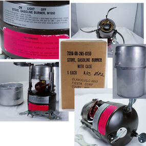
Stove Cooking Gasoline, M-1950 Burner, 2/66
... US Army Rogers M-1950 Stove Portable Gasoline Burner Vietnam Era Removable Hand pump set into base to pressurise fuel Maroon plastic flame control valve handle, that swings left to right through 180 degrees. ...Tramways/East Melbourne RSL Sub Branch - RSL Victoria Listing id: 27511 391 Gore Street Fitzroy melbourne 1 Gold adhesive label with Operating Instructions 1 Red adhesive label with Safety Warning under instructions US Army Rogers M-1950 Stove Portable Gasoline Burner Vietnam Era Removable Hand pump set into base to pressurise fuel Maroon plastic flame control valve handle, that swings left to right through 180 degrees. ...US Army Rogers M-1950 Stove Portable Gasoline Burner Vietnam Era Removable Hand pump set into base to pressurise fuel Maroon plastic flame control valve handle, that swings left to right through 180 degrees. Purpose built service spanner secured between burner support legs. Operating Instruction have worn off. Significant damage to Safety warning label. Still fully operational1 Gold adhesive label with Operating Instructions 1 Red adhesive label with Safety Warning under instructions -
 Trafalgar Holden Museum
Vehicle - VZ Holden Executive, 2004
... The advanced 3.6-litre Alloytec engines were more powerful, responsive and fuel-efficient than the outgoing Ecotec V6. To achieve 190 kW (255 hp), the Alloytec V6 gains variable valve timing on both inlet and exhaust sides as well as a dual stage intake manifold, while the 175 kW (235 hp) version retains variable valve timing on the inlet side only. ...The advanced 3.6-litre Alloytec engines were more powerful, responsive and fuel-efficient than the outgoing Ecotec V6. To achieve 190 kW (255 hp), the Alloytec V6 gains variable valve timing on both inlet and exhaust sides as well as a dual stage intake manifold, while the 175 kW (235 hp) version retains variable valve timing on the inlet side only. ...Released in August 2004, the VZ series was a minor facelift of the previous VY series that featured a new V6 engine in different tune guises. The powerplants included 175 and 190 kW (235 and 255 hp), 3.6-litre Alloytec V6 engines in place of the older 3.8-litre Ecotec V6. Other changes to the V6 was the loss of the supercharger that was included in the S models The VZ Commodore was available in several model variations, most of which carried over from the VY range, with the exception of the newly introduced SV6, a specification level that replaced the S range. All models in the Commodore range (Executive, Acclaim, Berlina, Calais, SV6, SV8 and SS) were available as sedans. The advanced 3.6-litre Alloytec engines were more powerful, responsive and fuel-efficient than the outgoing Ecotec V6. To achieve 190 kW (255 hp), the Alloytec V6 gains variable valve timing on both inlet and exhaust sides as well as a dual stage intake manifold, while the 175 kW (235 hp) version retains variable valve timing on the inlet side only. Sales of the VZ series failed to match those of the preceding VY in light of rising small car sales, higher fuel prices and growing interest in the whole new replacement, the VE series. Selected models bring advanced active safety features that electronically assist the driver to maintain vehicle control in emergency situations. VZ Holden 4 door sedan with red body paint and fabric upholsteryLion badge front grille,V6 badge on mudguards. Executive badge on RHS of boot and Comnmodore on LHS. Lion badge on middle of bootvehicle, vz holden, car -
 Puffing Billy Railway
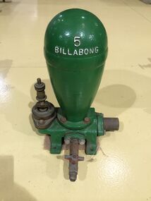
Functional object - Billabong Ram Pump Size #5, Unknown
... fuel or steam to operate. • They possess simplicity of construction and operation – only 2 moving parts. • Powered only by running water. • Require very minimal or almost no maintenance. • Heavy duty cast Iron base and Dome. This Pump recovered from the Clematis Creek in the Mid 1970's Used to pump water from the creek to the Paradise (Clematis) Hotel. Historic - Farm Equipment - Used to pump water from the creek to the Paradise (Clematis) Hotel. billabong puffing billy ram pump Billabong 5 Cast Iron Bronze valve ...Pump - Billabong Ram Pump Size #5 Based on available historical data, the Australian-made Billabong Hydraulic Ram is one of the oldest rams produced anywhere in the world The Billabong Hydraulic Ram was first introduced into Australia in 1855 by John Danks and Son Limited, John Danks & Son Pty Ltd began as a plumbing business in 1859, established by brothers John and Samuel. It occupied a prominent site in Bourke Street, Melbourne, for 100 years. The business quickly grew to include factories in Melbourne and Sydney which manufactured and supplied a variety of plumbing and engineering products such as brassware, pumps, windmills and bells. The company was registered in Victoria on 25 January 1889 to continue the hardware manufacturing and supply business founded by brothers John and Samuel Danks in 1859. The head office was based in Bourke Street, Melbourne while another branch was established in Sydney in the 1880s. The company had factories in Melbourne and Sydney. The John Danks and Son Limited catalogue published in 1890, listing Billabong Hydraulic Rams as one of its major machinery products. The catalogue also provides reference to the company’s ram experience and manufacture, beginning by stating that in 1890 they already had 35 years of experience with Billabong Hydraulic Rams. The Hydraulic Ram has stood the test of time and it remains one of the few really practical and efficient uses of natural energy today. It operates without almost any cost, will last indefinitely and, with only two moving parts, is simplicity itself. It requires minimum maintenance and minimum replacement of parts. It is not uncommon to find rams working continuously for many years without any attention. • The Rams do not require electricity, fuel or steam to operate. • They possess simplicity of construction and operation – only 2 moving parts. • Powered only by running water. • Require very minimal or almost no maintenance. • Heavy duty cast Iron base and Dome. This Pump recovered from the Clematis Creek in the Mid 1970's Used to pump water from the creek to the Paradise (Clematis) Hotel. Historic - Farm Equipment - Used to pump water from the creek to the Paradise (Clematis) Hotel.Cast Iron Bronze valveBillabong 5billabong, puffing billy, ram pump -
 Moorabbin Air Museum
Manual (Item) - (SP) AAP 7271.036-3 Pressure reducing valve, fuel, 7028-U1K1
... (SP) AAP 7271.036-3 Pressure reducing valve, fuel, 7028-U1K1...Moorabbin Air Museum Moorabbin Airport 12 First Street Moorabbin melbourne Manual (SP) AAP 7271.036-3 Pressure reducing valve, fuel, 7028-U1K1 ... -
Moorabbin Air Museum
Manual (Item) - RAAF manuals on - Block non-return connection, fuel drain cock, controller, safety and inwards relief valve, Mk.3 twin element hydraulic control valve, high energy ignition unit
... RAAF manuals on - Block non-return connection, fuel drain cock, controller, safety and inwards relief valve, Mk.3 twin element hydraulic control valve, high energy ignition unit...RAAF manuals on - Block non-return connection, fuel drain cock, controller, safety and inwards relief valve, Mk.3 twin element hydraulic control valve, high energy ignition unit...Moorabbin Air Museum Moorabbin Airport 12 First Street Moorabbin melbourne RAAF manuals on - Block non-return connection, fuel drain cock, controller, safety and inwards relief valve, Mk.3 twin element hydraulic control valve, high energy ignition unit Manual RAAF manuals on - Block non-return connection, fuel drain cock, controller, safety and inwards relief valve, Mk.3 twin element hydraulic control valve, high energy ignition unit ... -
Moorabbin Air Museum
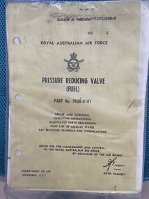
Manual (Item) - Pressure Reducing Valve (Fuel)
... Pressure Reducing Valve (Fuel)...United States Manual Pressure Reducing Valve (Fuel) ...Description: 77 pages. Published by RAAF. Published as 1st edition, July 1964. AAP 7213.003-6-15 Level of Importance: World. United States -
Moorabbin Air Museum
Drawing (Item) - Installation Fuel Lines to Selector Valve 15-48002
... Installation Fuel Lines to Selector Valve 15-48002...Installation Fuel Lines to Selector Valve 15-48002...Moorabbin Air Museum Moorabbin Airport 12 First Street Moorabbin melbourne Installation Fuel Lines to Selector Valve 15-48002 Drawing Installation Fuel Lines to Selector Valve 15-48002 ... -
Moorabbin Air Museum
Document (Item) - (SP) Technical Orders - multitude - list in "Context"
... Fuel Filter 03S12166D Overhaul with Parts Breakdown...Technical Order TO-6R-1-2 Engine Carburetor Installation...Technical Order TO-6R1-3-1-35 Bendix Injector Carburetor Overhaul...Technical Order TO-6R9-2-11-3 Valve...Moorabbin Air Museum Moorabbin Airport 12 First Street Moorabbin melbourne Possibly related to navigation Technical Order AN 03-10ABB-163 Cyl Plug Selector Valve Assy Overhaul with Parts Breakdown Technical Order AN 03-5-308 Switch Pressure Actuated Overhaul with Parts Breakdown Technical Order AN 05-55A-13 D-C Selsyn Position Indicators and Transmitters Technical Order AN-03-10ABB-237 Swing Check Valve Overhaul with Parts Breakdown Technical Order TO-00-20A-2 Airplane Maintenance Forms Technical Order TO-01-1-390 Food and Galley Equipment Responsibility Technical Order TO-01-1-515 Rework Solenoid Control Head Part 966129 Technical Order TO-01-1-619 Oxygen Regulators Inspection and Replacement Technical Order TO-02-10AB-1 R985 Aircraft Engines Operations Technical Order TO-03-1-6 Solenoid Meshing Devices Ops Service Overhaul Technical Order TO-06-1-8 Fuels and Lubricants Technical Order TO-06-10-1 Lubrication oils Grades and Use Technical Order TO-08-5-10 Radio SCR-578-A Defective Reels RL-48 Technical Order TO-1-1-383 Removal of Ammunition from Aircraft Technical Order TO-10-25-3 Film Developer Assy Operations Servicing Parts Catalog Technical Order TO-14S3-1-503 Inspection of Life Raft CO2 Cylinders Technical Order TO-15A1-2-12-3 Air Pressure Regulator Overhaul Technical Order TO-15H4-2-2-3 Ignition Units Overhaul Technical Order TO-15H6-2-2-123 Cockpit Temperature Control Box Technical Order TO-15H6-2-2-13 Cockpit Temperature Control Box Technical Order TO-15H6-2-2-163 Cockpit Temperature Control Box Overhaul Technical Order TO-1F-1-525 Safety Wirting Pilot Oxygen Shutoff Valve Technical Order TO-1F-86-210 Sabre Electrical Connector for Test Equipment Technical Order TO-2R-0470-12 AN 02A-40EB-2 Aircraft Engines Service Technical Order TO-2R-0470-13 AN 02A-40EB-3 Aircraft Engines Overhaul Technical Order TO-2R-0470-14 AN 02A-40EB-4 Aircraft Engines Parts Breakdown Technical Order TO-4S-1-2 High Pressure Air Valve Cores Technical Order TO-4S5-2-3 Tail Skid Shock Struts Overhaul Technical Order TO-5F4-3-3 True Airspeed Signal Control Amplifier Overhaul Technical Order TO-6J13-2-1-501 Dual Float Switch Assy Installation Technical Order TO-6J14-1-5 Torque Values Self Sealing Bladder Cell Multi Bolt Fittings Technical Order TO-6J3-4-15-4A VS-2 Fuel Regulator Parts Breakdown Technical Order TO-6J5-15-3 Fuel Filetr Assy Overhaul Technical Order TO-6J5-15-4 Fuel Filter Assy Parts Breakdown Technical Order TO-6J5-18-3 Micronic Filters Overhaul Technical Order TO-6J5-18-4 Micronic Filters Parts Breakdown Technical Order TO-6J5-24-3 Av Fuel Filter Replaceable Micronic Element Technical Order TO-6J5-5-3 Fuel Filter 03S12166D Overhaul with Parts Breakdown Technical Order TO-6R-1-2 Engine Carburetor Installation Technical Order TO-6R1-3-1-35 Bendix Injector Carburetor Overhaul Technical Order TO-6R9-2-11-3 Valve Check Overhaul with Parts Breakdown Technical Order TO-6R9-2-12-3 Swing Check Valve Overhaul with Parts Breakdown Technical Order TO-6R9-2-14-3 Check Valve Flow Indicator Overhaul wth Parts Breakdown Technical Order TO-8A6-3-3-3 AC Generator Overhaul Technical Order TO-8A6-8-4-4 Engine Driven Aircraft Generator Parts Breakdown Technical Order TO-8A6-9-3-3 Aircraft AC Generator Overhaul Technical Order TO-8D1-21-3-33 Fractional Horsepower Motor 5BA25AJ28B Overhaul with Parts Breakdown Technical Order TO-8D1-21-3-33 Fractional Horsepower Motor 5BA25MJ426B Overhaul with Parts Breakdown Technical Order TO-8D1-29-2-3 Direct Current Motor Parts Breakdown Technical Order TO-8D1-9-13-23 Oil Cooler Flap Control Overhaul Parts Breakdown Technical Order TO-8D1-9-19-3 Direct Current Motor Overhaul with Parts Breakdown Technical Order TO-8D1-9-21-3 Electromechanical Linear Actuator Overhaul Technical Order TO-8D1-9-21-4 Electromechanical Linear Actuator Parts Breakdown Technical Order TO-8D1-9-22-3 Electromechanical Power Unit Overhaul Technical Order TO-8D1-9-22-4 Electromechanical Power Unit Parts Breakdown Technical Order TO-8D3-8-6-3 Position Light Flasher Overhaul Technical Order TO-8D6-5-4-504 Mod Westinghouse Generator A45J247 Technical Order TO-8E2-5-2-13 Aircraft Magnetos Overhaul Technical Order TO-8E2-5-2-14 Aircraft Magnetos Parts Breakdown Technical Order TO-8RI-3-5-3 Generator Field Control Relay M-2 Overhaul Technical Order TO-9H4-2-24-4A Stratopower Hydraulic Pump Parts Breakdown Document (SP) Technical Orders - multitude - list in "Context" ...Possibly related to navigationtechnical order an 03-10abb-163 cyl plug selector valve assy overhaul with parts breakdown, technical order an 03-5-308 switch pressure actuated overhaul with parts breakdown, technical order an 05-55a-13 d-c selsyn position indicators and transmitters, technical order an-03-10abb-237 swing check valve overhaul with parts breakdown, technical order to-00-20a-2 airplane maintenance forms, technical order to-01-1-390 food and galley equipment responsibility, technical order to-01-1-515 rework solenoid control head part 966129, technical order to-01-1-619 oxygen regulators inspection and replacement, technical order to-02-10ab-1 r985 aircraft engines operations, technical order to-03-1-6 solenoid meshing devices ops service overhaul, technical order to-06-1-8 fuels and lubricants, technical order to-06-10-1 lubrication oils grades and use, technical order to-08-5-10 radio scr-578-a defective reels rl-48, technical order to-1-1-383 removal of ammunition from aircraft, technical order to-10-25-3 film developer assy operations servicing parts catalog, technical order to-14s3-1-503 inspection of life raft co2 cylinders, technical order to-15a1-2-12-3 air pressure regulator overhaul, technical order to-15h4-2-2-3 ignition units overhaul, technical order to-15h6-2-2-123 cockpit temperature control box, technical order to-15h6-2-2-13 cockpit temperature control box, technical order to-15h6-2-2-163 cockpit temperature control box overhaul, technical order to-1f-1-525 safety wirting pilot oxygen shutoff valve, technical order to-1f-86-210 sabre electrical connector for test equipment, technical order to-2r-0470-12 an 02a-40eb-2 aircraft engines service, technical order to-2r-0470-13 an 02a-40eb-3 aircraft engines overhaul, technical order to-2r-0470-14 an 02a-40eb-4 aircraft engines parts breakdown, technical order to-4s-1-2 high pressure air valve cores, technical order to-4s5-2-3 tail skid shock struts overhaul, technical order to-5f4-3-3 true airspeed signal control amplifier overhaul, technical order to-6j13-2-1-501 dual float switch assy installation, technical order to-6j14-1-5 torque values self sealing bladder cell multi bolt fittings, technical order to-6j3-4-15-4a vs-2 fuel regulator parts breakdown, technical order to-6j5-15-3 fuel filetr assy overhaul, technical order to-6j5-15-4 fuel filter assy parts breakdown, technical order to-6j5-18-3 micronic filters overhaul, technical order to-6j5-18-4 micronic filters parts breakdown, technical order to-6j5-24-3 av fuel filter replaceable micronic element, technical order to-6j5-5-3 fuel filter 03s12166d overhaul with parts breakdown, technical order to-6r-1-2 engine carburetor installation, technical order to-6r1-3-1-35 bendix injector carburetor overhaul, technical order to-6r9-2-11-3 valve check overhaul with parts breakdown, technical order to-6r9-2-12-3 swing check valve overhaul with parts breakdown, technical order to-6r9-2-14-3 check valve flow indicator overhaul wth parts breakdown, technical order to-8a6-3-3-3 ac generator overhaul, technical order to-8a6-8-4-4 engine driven aircraft generator parts breakdown, technical order to-8a6-9-3-3 aircraft ac generator overhaul, technical order to-8d1-21-3-33 fractional horsepower motor 5ba25aj28b overhaul with parts breakdown, technical order to-8d1-21-3-33 fractional horsepower motor 5ba25mj426b overhaul with parts breakdown, technical order to-8d1-29-2-3 direct current motor parts breakdown, technical order to-8d1-9-13-23 oil cooler flap control overhaul parts breakdown, technical order to-8d1-9-19-3 direct current motor overhaul with parts breakdown, technical order to-8d1-9-21-3 electromechanical linear actuator overhaul, technical order to-8d1-9-21-4 electromechanical linear actuator parts breakdown, technical order to-8d1-9-22-3 electromechanical power unit overhaul, technical order to-8d1-9-22-4 electromechanical power unit parts breakdown, technical order to-8d3-8-6-3 position light flasher overhaul, technical order to-8d6-5-4-504 mod westinghouse generator a45j247, technical order to-8e2-5-2-13 aircraft magnetos overhaul, technical order to-8e2-5-2-14 aircraft magnetos parts breakdown, technical order to-8ri-3-5-3 generator field control relay m-2 overhaul, technical order to-9h4-2-24-4a stratopower hydraulic pump parts breakdown -
Moorabbin Air Museum
Manual - Douglas aircraft, Douglas Service Magazine 1965
... Relay valve control for pneumatic brakes...Tail wheel...Griffon engine fuel...Relay valve control for pneumatic brakes Tail wheel Griffon engine fuel injector pumps L type cartridge starter Descriptive & maintenance notes, including spare parts schedule, circa 1965 Douglas Service Magazine 1965 Manual Douglas aircraft ...Descriptive & maintenance notes, including spare parts schedule, circa 1965non-fictionDescriptive & maintenance notes, including spare parts schedule, circa 1965non return valves, anticer pumps., relay valve control for pneumatic brakes, tail wheel, griffon engine fuel injector pumps, l type cartridge starter -
Moorabbin Air Museum
Drawing - Valve Assy - Drop Fuel Tank Press and Thermal Relief, Commonwealth Aircraft Corporation Drawing No. 27-48208
... Valve Assy - Drop Fuel Tank Press and Thermal Relief ...Moorabbin Air Museum Moorabbin Airport 12 First Street Moorabbin melbourne Commonwealth Aircraft Corporation Drawing No. 27-48208 Drawing Valve Assy - Drop Fuel Tank Press and Thermal Relief ... -
Moorabbin Air Museum
Drawing - Fitting Assy - Two STA Wing L.E.F.S. BP 72 1/4 Fuel Disct. & CH. Valve Complete, Commonwealth Aircraft Corporation Drawing No. 27-482125
... BP 72 1/4 Fuel Disct. & CH. Valve Complete...BP 72 1/4 Fuel Disct. & CH. Valve Complete ... -
Moorabbin Air Museum
Drawing - Union - Two STA. Wing L.E.F.S. BP 72 1/4 Fuel Disconnect & Fuel Check Valve, Commonwealth Aircraft Corporation Drawing No. 27-482127
... BP 72 1/4 Fuel Disconnect & Fuel Check Valve ...BP 72 1/4 Fuel Disconnect & Fuel Check Valve ...