Ballarat Tramway Museum
Document - Folder with papers, State Electricity Commission of Victoria (SECV), 1960's
... Type ‘B’ Main Cylinder
4870 6/1 7A BA-T3-6734 Brass Nut for Switch Mechanism
4829 6/2 7B BA-T3-6735 Tongue Clip Link for Switch Mechanism
4871 6/3 7C BA-T3-6736 Fulcrum for Switch Mechanism
4872 6/4 7D BA-T3-6737 Plunger for Switch Mechanism
4832 7/6 8 BA-T3-6754 Pivot for Switch Mechanism
No numbers 9 or 10
4873 17/5 11 BA-T7-7639 Detail of Motor Pinion for Brill Cars
4831.2 21/4 B 12 BA-T7-7661A Half Ball Hanger Links – single bogie trucks
4874 21/6 13A BA-T7-7663 Axle Box Inner Spring Driving Wheels Maximum Traction Truck 22E
4875 22/1 13B BA-T7-7664 Axle Box Outer Spring Driving Wheels Maximum Traction Truck 22E
4876 22/2 14 BA-T7-7665 Body Spring Brill Maximum Traction Truck 22E
4830.2 22/3B 15 BA-T7-7666A Half Ball Brake Hanger Link Driving Wheel Brill Maximum Traction Truck 22E
4877 22/4 16 BA-T7-7667 Body Spring, Brush Maximum Traction Truck 22E
4820.2 22/6 A 17 BA-T7-7669 Wear cups for Half Ball Brake Hanger Links, Single & Double Bogie Trucks
4878 50/5 18 BA-T8-8149 Connections of Line Breaker and Ratchet Switch for use with Drum Controller
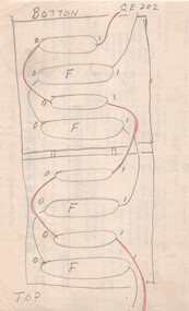
4879 74/6 19 BA-T13-8757/9 Signal boxes, Back of Panel Wiring and External Connections
4880 45/1 20 BA-T8-8116 Trolley Harp
4806 15/3 21 BA-T7-7625 Equalizing Lever, Fulcrum, Brill 21 E truck
4881 15/5 22 BA-T7-7626A Brake Beam Fulcrum Brill 21E truck
4808 16/1 23 BA-T7-7628 Pinion Remover, GE 201G and GE 202 motors
4882 16/3 24 BA-T7-7630 Spring Posts, Brill 21E Truck
4883 21/3 25 BA-T7-7660 Brake Shoe Holder, Driving Wheel, Maximum Traction Truck Brill 22E
4884 21/5 26 BA-T7-7662 Brake Rod Guide, Single Bogie Trucks
4885 22/5 27 BA-T7-7668 Brake Shoe Holder, Pony Wheel, Maximum Traction Truck Brill 22E
4809 42/2 B 28 BA-T8-8101 Trolley Wheel and Axle
4815 42/1 B 29 BA-T8-8102A Motor Suspension Bearing, GE 202 Motor
4796.2 42/5 30 BA-T8-8104 Connection Diagram WH 225N Motor
4886 42/6 B 31 BA-T8-8105B Motor Suspension Bearing, GE 201 Motor
4797.2 48/6 32 BA-T8-8137 WH T1F Controllers
4816 49/2 33 BA-T8-8138 Connection Diagram GE 202 Motor
4887 49/3 34 BA-T8-8139 Connection Diagram K-36-J Controller
4888 50/3 35 BA-T8-8146 GE K-36-JR Controllers, with line breaker (Connection diagram)
4889 50/6 36 BA-T8-8150 Commutator for Westinghouse 225N Motor
4846 51/1 37 BA-T8-8151A Armature Bearing Lining, Commutator End, Type GE 201G Motor
4813 51/2 38 BA-T8-8152 Armature Winding Diagram Westinghouse 225 Motor
4840.2 51/40 39 BA-T8-8154A Armature Bearing Lining, Pinion End, Type GE201G Motor
4890 51/6 40 BA-T8-8156 Armature Bearing Lining, Pinion End, Type GE202A Motor
4891 52/1 41 BA-T8-8157A Armature Bearing Lining, Commutator End, Type GE202A Motor
4892 64/5 42A BA-T9-8392A Step Hangers, Single and Double Bogie Trucks, Hinged Type
4785.2 64/6B 42B BA-T9-8392/1A Step Hangers, Single and Maximum Traction Trucks, Fixed Type
4812.2 43/1 43 BA-T8-8106B GE K36J Controller, Main Cylinder Segments
4893 50/2 44 BA-T8-8145A GE B23E Controller, Main Cylinder Segments
4816 65/2 45 BA-T9-8394B Door Lock for Motorman’ Cabin Maximum Traction Trucks.
4810 73/3 46 BA-T13-8757 Ballarat Electric Tramways Signalling System, Arrangements & Details of Box....Type ‘B’ Main Cylinder
4870 6/1 7A BA-T3-6734 Brass Nut for Switch Mechanism
4829 6/2 7B BA-T3-6735 Tongue Clip Link for Switch Mechanism
4871 6/3 7C BA-T3-6736 Fulcrum for Switch Mechanism
4872 6/4 7D BA-T3-6737 Plunger for Switch Mechanism
4832 7/6 8 BA-T3-6754 Pivot for Switch Mechanism
No numbers 9 or 10
4873 17/5 11 BA-T7-7639 Detail of Motor Pinion for Brill Cars
4831.2 21/4 B 12 BA-T7-7661A Half Ball Hanger Links – single bogie trucks
4874 21/6 13A BA-T7-7663 Axle Box Inner Spring Driving Wheels Maximum Traction Truck 22E
4875 22/1 13B BA-T7-7664 Axle Box Outer Spring Driving Wheels Maximum Traction Truck 22E
4876 22/2 14 BA-T7-7665 Body Spring Brill Maximum Traction Truck 22E
4830.2 22/3B 15 BA-T7-7666A Half Ball Brake Hanger Link Driving Wheel Brill Maximum Traction Truck 22E
4877 22/4 16 BA-T7-7667 Body Spring, Brush Maximum Traction Truck 22E
4820.2 22/6 A 17 BA-T7-7669 Wear cups for Half Ball Brake Hanger Links, Single & Double Bogie Trucks
4878 50/5 18 BA-T8-8149 Connections of Line Breaker and Ratchet Switch for use with Drum Controller
4879 74/6 19 BA-T13-8757/9 Signal boxes, Back of Panel Wiring and External Connections
4880 45/1 20 BA-T8-8116 Trolley Harp
4806 15/3 21 BA-T7-7625 Equalizing Lever, Fulcrum, Brill 21 E truck
4881 15/5 22 BA-T7-7626A Brake Beam Fulcrum Brill 21E truck
4808 16/1 23 BA-T7-7628 Pinion Remover, GE 201G and GE 202 motors
4882 16/3 24 BA-T7-7630 Spring Posts, Brill 21E Truck
4883 21/3 25 BA-T7-7660 Brake Shoe Holder, Driving Wheel, Maximum Traction Truck Brill 22E
4884 21/5 26 BA-T7-7662 Brake Rod Guide, Single Bogie Trucks
4885 22/5 27 BA-T7-7668 Brake Shoe Holder, Pony Wheel, Maximum Traction Truck Brill 22E
4809 42/2 B 28 BA-T8-8101 Trolley Wheel and Axle
4815 42/1 B 29 BA-T8-8102A Motor Suspension Bearing, GE 202 Motor
4796.2 42/5 30 BA-T8-8104 Connection Diagram WH 225N Motor
4886 42/6 B 31 BA-T8-8105B Motor Suspension Bearing, GE 201 Motor
4797.2 48/6 32 BA-T8-8137 WH T1F Controllers
4816 49/2 33 BA-T8-8138 Connection Diagram GE 202 Motor
4887 49/3 34 BA-T8-8139 Connection Diagram K-36-J Controller
4888 50/3 35 BA-T8-8146 GE K-36-JR Controllers, with line breaker (Connection diagram)
4889 50/6 36 BA-T8-8150 Commutator for Westinghouse 225N Motor
4846 51/1 37 BA-T8-8151A Armature Bearing Lining, Commutator End, Type GE 201G Motor
4813 51/2 38 BA-T8-8152 Armature Winding Diagram Westinghouse 225 Motor
4840.2 51/40 39 BA-T8-8154A Armature Bearing Lining, Pinion End, Type GE201G Motor
4890 51/6 40 BA-T8-8156 Armature Bearing Lining, Pinion End, Type GE202A Motor
4891 52/1 41 BA-T8-8157A Armature Bearing Lining, Commutator End, Type GE202A Motor
4892 64/5 42A BA-T9-8392A Step Hangers, Single and Double Bogie Trucks, Hinged Type
4785.2 64/6B 42B BA-T9-8392/1A Step Hangers, Single and Maximum Traction Trucks, Fixed Type
4812.2 43/1 43 BA-T8-8106B GE K36J Controller, Main Cylinder Segments
4893 50/2 44 BA-T8-8145A GE B23E Controller, Main Cylinder Segments
4816 65/2 45 BA-T9-8394B Door Lock for Motorman’ Cabin Maximum Traction Trucks.
4810 73/3 46 BA-T13-8757 Ballarat Electric Tramways Signalling System, Arrangements & Details of Box. ...
Yields information about the drawings that were used by the depot or workshop staff as reference drawings. Has a strong association with the depot workshop staff. Yields information about equipment on Ballarat tramcars and Signalling.Folder containing 46 blueprints or Dyeline prints of SEC tram equipment drawings.
Front of folder made from a cloth back sheet of paper extended to secure to a thick cardboard runner. Rear of folder made from an old tram advertising panel or cardboard sheet, cut to size and secured to a thick cardboard runner with a cloth backing on both sides. Sheets secured with three brass screwed clips.
Front cover damaged in bottom right hand corner. Rear cover breaking apart on outside around cloth binding. Heavy dirt marks from “grease” on bottom half of rear cover.
Contains 46 drawings which have been individually catalogued and numbered on the rear of each drawing within the folder. Some of the drawings have been folded.
Reg Item Micro Film No. Old BTPS No. SEC Drawing No Title
4807 42/4 1 VB4/8103C Westinghouse T1F Controller Main Cylinder Segments.
4867 47/2 2 BA-T8-8128 Westinghouse 225N Motor Case Bolt
4830 22/3 B 3 BA-T7-7666 Half Ball Brake Hanger Link, Driving Wheel, Brill Maximum Traction Truck 22E
4868 44/3A 4 BA-T8-8113 Split Suspension Bearing for Type W225 Motor (Westinghouse)
4869 52/2 5 BA-T8-8158 Contact Tips for G.E. Compressor Controller
4818 52/3 6 BA-T8-8159 GE B-23 Contact Finger Tips for G.E. Type ‘B’ Main Cylinder
4870 6/1 7A BA-T3-6734 Brass Nut for Switch Mechanism
4829 6/2 7B BA-T3-6735 Tongue Clip Link for Switch Mechanism
4871 6/3 7C BA-T3-6736 Fulcrum for Switch Mechanism
4872 6/4 7D BA-T3-6737 Plunger for Switch Mechanism
4832 7/6 8 BA-T3-6754 Pivot for Switch Mechanism
No numbers 9 or 10
4873 17/5 11 BA-T7-7639 Detail of Motor Pinion for Brill Cars
4831.2 21/4 B 12 BA-T7-7661A Half Ball Hanger Links – single bogie trucks
4874 21/6 13A BA-T7-7663 Axle Box Inner Spring Driving Wheels Maximum Traction Truck 22E
4875 22/1 13B BA-T7-7664 Axle Box Outer Spring Driving Wheels Maximum Traction Truck 22E
4876 22/2 14 BA-T7-7665 Body Spring Brill Maximum Traction Truck 22E
4830.2 22/3B 15 BA-T7-7666A Half Ball Brake Hanger Link Driving Wheel Brill Maximum Traction Truck 22E
4877 22/4 16 BA-T7-7667 Body Spring, Brush Maximum Traction Truck 22E
4820.2 22/6 A 17 BA-T7-7669 Wear cups for Half Ball Brake Hanger Links, Single & Double Bogie Trucks
4878 50/5 18 BA-T8-8149 Connections of Line Breaker and Ratchet Switch for use with Drum Controller
4879 74/6 19 BA-T13-8757/9 Signal boxes, Back of Panel Wiring and External Connections
4880 45/1 20 BA-T8-8116 Trolley Harp
4806 15/3 21 BA-T7-7625 Equalizing Lever, Fulcrum, Brill 21 E truck
4881 15/5 22 BA-T7-7626A Brake Beam Fulcrum Brill 21E truck
4808 16/1 23 BA-T7-7628 Pinion Remover, GE 201G and GE 202 motors
4882 16/3 24 BA-T7-7630 Spring Posts, Brill 21E Truck
4883 21/3 25 BA-T7-7660 Brake Shoe Holder, Driving Wheel, Maximum Traction Truck Brill 22E
4884 21/5 26 BA-T7-7662 Brake Rod Guide, Single Bogie Trucks
4885 22/5 27 BA-T7-7668 Brake Shoe Holder, Pony Wheel, Maximum Traction Truck Brill 22E
4809 42/2 B 28 BA-T8-8101 Trolley Wheel and Axle
4815 42/1 B 29 BA-T8-8102A Motor Suspension Bearing, GE 202 Motor
4796.2 42/5 30 BA-T8-8104 Connection Diagram WH 225N Motor
4886 42/6 B 31 BA-T8-8105B Motor Suspension Bearing, GE 201 Motor
4797.2 48/6 32 BA-T8-8137 WH T1F Controllers
4816 49/2 33 BA-T8-8138 Connection Diagram GE 202 Motor
4887 49/3 34 BA-T8-8139 Connection Diagram K-36-J Controller
4888 50/3 35 BA-T8-8146 GE K-36-JR Controllers, with line breaker (Connection diagram)
4889 50/6 36 BA-T8-8150 Commutator for Westinghouse 225N Motor
4846 51/1 37 BA-T8-8151A Armature Bearing Lining, Commutator End, Type GE 201G Motor
4813 51/2 38 BA-T8-8152 Armature Winding Diagram Westinghouse 225 Motor
4840.2 51/40 39 BA-T8-8154A Armature Bearing Lining, Pinion End, Type GE201G Motor
4890 51/6 40 BA-T8-8156 Armature Bearing Lining, Pinion End, Type GE202A Motor
4891 52/1 41 BA-T8-8157A Armature Bearing Lining, Commutator End, Type GE202A Motor
4892 64/5 42A BA-T9-8392A Step Hangers, Single and Double Bogie Trucks, Hinged Type
4785.2 64/6B 42B BA-T9-8392/1A Step Hangers, Single and Maximum Traction Trucks, Fixed Type
4812.2 43/1 43 BA-T8-8106B GE K36J Controller, Main Cylinder Segments
4893 50/2 44 BA-T8-8145A GE B23E Controller, Main Cylinder Segments
4816 65/2 45 BA-T9-8394B Door Lock for Motorman’ Cabin Maximum Traction Trucks.
4810 73/3 46 BA-T13-8757 Ballarat Electric Tramways Signalling System, Arrangements & Details of Box.On front cover of folder, "1 - 46"trams, tramways, drawings, ballarat, sec, depot, workshops
 Ballarat Tramway Museum
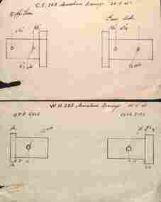 Ballarat Tramway Museum
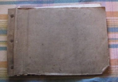 Ballarat Tramway Museum
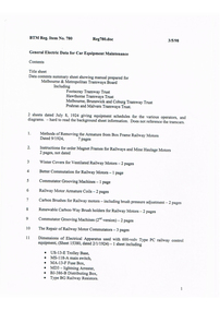 Ballarat Tramway Museum