Showing 18 items matching "process specifications"
-
 Moorabbin Air Museum
Manual - Rolls Royce Derwent engines, Derwent Repair
... Process specifications... schemes Process specifications Turbine repair memoranda Overview ...Overview of processes to repair Derwent engine components, circa late 1950snon-fictionOverview of processes to repair Derwent engine components, circa late 1950sgeneral repair, turbine repair schemes, process specifications, turbine repair memoranda -
 National Wool Museum
Book, The Wool Year Book 1914, 1914
... statistics, supplier lists, descriptions and specifications..., supplier lists, descriptions and specifications of processes, diary ..."Textile Mercury Annuals:The Wool year book and diary 1914".Book, 592 pages. Dark green hard backed book, green cord bookmark, thumb cutouts designating the sections. Includes statistics, supplier lists, descriptions and specifications of processes, diary in blue paper.Cover: 'Textile Mercury' / Annuals / The Wool / Year Book / 1914. / With / CRITOHLEY, SHARP & TETLOW'S / Complimentstextile industry textile machinery textile history, textile mercury ltd, textile industry, textile machinery, textile history -
 Bendigo Military Museum
Photograph - Photographic Technicians operating the KLIMSCH Camera at the Army Survey Regiment, Fortuna, Bendigo, c1988
These nine photographs were most likely taken in c1988 in Lithographic Squadron at the Army Survey Regiment, Fortuna, Bendigo. The equipment operated by the technicians is the KLIMCH camera. The main tasks undertaken by the technicians were most likely enlargements and reductions of map reproduction material. The KLIMSCH Commodore camera was introduced in 1953 and was the largest in the Southern Hemisphere. It was replaced with a new model of the same size in 1979. The new model with its computer-based interface provided productivity gains with improved speed and its consistent results led to less wastage in time and materials. Its variomat lens system provided improved retention of map feature linear weights during the camera reduction process. The camera which was specially made for the Army in Germany was fully automatic and power operated. It was claimed to be one of the biggest automatic cameras of its type in the world. It was made to the specifications of the Royal Australian Army Survey Corps to assist in the production of the very high standard maps for the Army. There are several more photos catalogued in the Victorian Collections database of RA Svy personnel operating the KLIMSCH camera.This is a set of four photographs of technicians operating the KLIMSCH Camera at the Army Headquarters Survey Regiment, Bendigo c1988. The photographs are on 35mm colour slides scanned at 96 dpi. They are part of the Army Survey Regiment’s Collection. .1) - Photo, colour, c1988, KLIMSCH Camera. .2) - Photo, colour, c1988, KLIMSCH Camera, unidentified technician. .3) - Photo, colour, c1988, KLIMSCH Camera. .4) - Photo, colour, c1988, KLIMSCH Camera, L to R: SPR Shona Hastie, CPL Paul Baker. .5) - Photo, colour, c1988, KLIMSCH Camera. .6) & .7) - Photo, colour, c1988, KLIMSCH Camera, SPR Shona Hastie. .8) & .9) - Photo, colour, c1988, KLIMSCH Camera, SPR Russell Pajank.35mm colour slides are in good condition.rasvy, royal australian survey corps, army survey regiment, army svy regt, fortuna, asr, litho sqn -
 Bendigo Military Museum
photograph - Cartographic Squadron Production – Army Survey Regiment, Fortuna, c1980
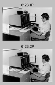
This collection of 12 photos was most likely taken in 1980. The photos were most likely taken in Cartographic Squadron’s Ante Room, the Attic and small offices on the top floor of Fortuna Villa. The computer based Editwriter typesetting system was introduced in 1975 as a replacement to the aging Fotosetter machine. It was operated by a specialised technician, who generated a large variety of map type styles and sizes quickly and reliably, as well as text panels. CPL Richards performed this task for several years and in photo .1P and .2P is reading off a type order next to the computer monitor. Output on Copy proof adhesive backed stripping type film replaced messy wax and spray adhesives in 1978. The Editwriter capability supported all RASvy units and contractor type setting requirements. Scribing was the cartographic process of drafting features such as drainage, relief, vegetation, roads and culture on specially coated map reproduction material. The cartographic technician scribed out the map feature such as a contour to a specified line width on the map sheet, using a tool affixed with a sapphire tipped cutter. The quality control edit (Proving) stage of map production was the first opportunity to inspect a proof of the map independently and systematically. Proving tasks were carried out by technicians conversant of the map product specification and task requirement, however, was not involved in its production. Corrections were identified, marked up and sent to back to the correcting section or contractors. Terrain Embossing was a manual map production technique to produce hill shading on medium to small scale graphics and air charts. SPR John Martin is seen in photos .8P to.10P using a fine embossing metal stylus to push down on the drainage impression on a thin malleable opaque plastic material (AK Poligraphy). Ridge lines were then pushed down using the contour impression as a guide, on the opposing side of the AK Poligraphy to create a 3D plastic model terrain effect. The map impression was sprayed with white paint and photographed to create a contone tone hill shade. SPR Gina (Coore) Neilson is seen in photo .11P washing a contone positive of a land mass in a solution. The contone components were registered to the map sheet, as shown in photo .12P and masked using an air brush and a halftone negative was then created. The terrain embossing method of producing hill shading was more efficient to produce than previous specialised artistic methods such pencil/eraser and air brush. Furthermore, a more consistent enhancement of terrain on charts was achieved between technicians.This is a set of 12 photographs of Cartographic Squadron performing four map production tasks at the Army Survey Regiment, Fortuna, Bendigo c1980. The first ten photographs were on 35mm negative film and were scanned at 96 dpi. Photos .11P and .12P were on photographic paper and scanned at 300 dpi. They are part of the Army Survey Regiment’s Collection. .1) - Photo, black & white, c1980, Editwriter typesetter, CPL Paul Richards. .2) - Photo, black & white, c1980, Editwriter typesetter, CPL Paul Richards. .3) - Photo, black & white, c1980, Scribing contours on a RAAF Chart, SPR Megan (McBurney) Reynolds. .4) - Photo, black & white, c1980, Scribing contours on a RAAF Chart, SPR Megan (McBurney) Reynolds. .5) - Photo, black & white, c1980, Scribing contours on a RAAF Chart, SPR Rod Skidmore. .6) - Photo, black & white, c1980, Scribing contours on a RAAF Chart, SPR Rod Skidmore. .7) - Photo, black & white, c1980, Formal quality control edit (Proving), CPL Ian Belmont. .8) - Photo, black & white, c1980, Hill Shade Terrain Embossing, SPR John Martin. .9) - Photo, black & white, c1980, Hill Shade Terrain Embossing, SPR John Martin. .10) - Photo, black & white, c1980, Hill Shade Terrain Embossing, SPR John Martin. .11) - Photo, black & white, c1980, Hill Shade Terrain Embossing, SPR Gina (Coore) Neilson. .12) - Photo, black & white, c1980, Hill Shade Terrain Embossing, unidentified..1P to .10P No personnel are identified. .11P and .12P annotated ‘Terrain Embossing’royal australian survey corps, rasvy, army survey regiment, army svy regt, fortuna, asr, carto -
 Bendigo Military Museum
Photograph - Photographic Technicians operating the KLIMSCH Camera at the Army Survey Regiment, Fortuna, c1980s
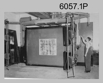
These four photographs were most likely taken in the mid-1980s in Lithographic Squadron at the Army Survey Regiment, Fortuna, Bendigo. The equipment operated by the technicians is the KLIMSCH camera. The main tasks undertaken by the technicians were most likely enlargements and reductions of map reproduction material. The KLIMSCH Commodore camera was introduced in 1953 and was the largest in the Southern Hemisphere. It was replaced with a new model of the same size in 1979. The new model with its computer-based interface provided productivity gains with improved speed and its consistent results led to less wastage in time and materials. Its variomat lens system provided improved retention of map feature linear weights during the camera reduction process. The camera which was specially made for the Army in Germany was fully automatic and power operated. It was claimed to be one of the biggest automatic cameras of its type in the world. It was made to the specifications of the Royal Australian Army Survey Corps to assist in the production of the very high standard maps for the Army. This is a set of four photographs of technicians operating the KLIMSCH Camera at the Army Headquarters Survey Regiment, Bendigo c1985. The photographs were on 35mm negative film and scanned at 96 dpi. They are part of the Army Survey Regiment’s Collection. .1) Photo, black & white, c1985, Frank Lenane operating the KLIMSCH Camera. .2) - Photo, black & white, c1985, KLIMSCH Camera. .3) to .4) - Photo, black & white, c1985, John Whaling operating the KLIMSCH Camera..1P to .4P – no annotationroyal australian survey corps, rasvy, army survey regiment, army svy regt, fortuna, asr, litho -
 Bendigo Military Museum
Photograph - Photographic Technicians performing tasks at the Army Headquarters Survey Regiment, c1960s
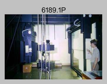
These eight photographs were most likely taken in the 1960s in Lithographic Squadron at the Army Headquarters Survey Regiment, Fortuna, Bendigo. Although Photo .1P is not annotated the remainder have the name of the technicians written on the back. The equipment operated by the technicians is the KLIMCH Commodore camera. The main tasks undertaken by the technicians were most likely enlargements and reductions of map reproduction material. The KLIMSCH Commodore camera was introduced in 1953 and was the largest in the Southern Hemisphere. It was replaced with a new model of the same size in 1979. The new model with its computer-based interface provided productivity gains with improved speed and its consistent results led to less wastage in time and materials. Its variomat lens system provided improved retention of map feature linear weights during the camera reduction process. The typed description pasted on the back of photo .5P states “Cpl R. MacKenzie of Bentley, Perth (WA) of the AHQ Survey Regt, located at “Fortuna”, Bendigo, (Vic). Has been in the Army for 5 years. He removes the lens cap from the 70 inch F16 lens of the giant KLIMSCH camera used in map making for the Army. The camera which was specially made for the Army in Germany is fully automatic and power operated. It is claimed to be one of the biggest automatic cameras of its type in the world. It was made to the specifications of the Aust Army Survey Corps to assist in the production of the very high standard maps for the Army. The AHQ Survey Regt also assists Commonwealth and other Govt departments in the printing of maps required other than for Army needs. The KLIMSCH camera is used for cartographic mapping photography.” This is a set of photographs of technicians operating photographic reproduction equipment at the Army Headquarters Survey Regiment, Bendigo c1960s. The photographs were printed on photographic paper and are part of the Army Survey Regiment’s Collection. The photographs were scanned at 300 dpi. .1) - Photo, black & white, c1960s, Les ‘Snow’ Taylor, Lithographic Squadron .2) - Photo, black & white, c1960s, Les ‘Snow’ Taylor, Lithographic Squadron .3) - Photo, black & white, c1960s, John Rolfe, Lithographic Squadron .4) - Photo, black & white, c1960s, John Rolfe, Lithographic Squadron .5) - Photo, black & white, c1960s, CPL R. MacKenzie, Lithographic Squadron .6) - Photo, black & white, c1960s, unidentified, Lithographic Squadron .7) - Photo, black & white, c1960s, George Graham, Lithographic Squadron .8) - Photo, black & white, c1960s, L to R: Bill Snelson, George Graham, Lithographic Squadron.1P – no annotation .2 to .4 – personnel names (less rank) annotated on back. .5 – name and rank annotated on back, with detailed typed description .6 to .8 – personnel names (less rank) annotated on back. royal australian survey corps, rasvy, army survey regiment, army svy regt, fortuna, asr, litho -
 Bendigo Military Museum
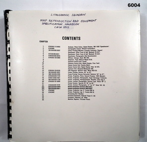
Manual - Map Reproduction and Equipment Specification Handbook, Circa 1975
Manual used by Lithographic Technicians as a register of Map reproduction equipment. Possible uses include to identify and quantify available equipment as part of the stocktaking process.90 page technical manual/ handbook. Does not have a front cover. Contents page and pages within the document have black and white stock descriptions followed by photos of equipment. The manual is printed on photographic paper and is bounded by a black plastic spiral spline.royal australian survey corps, rasvy, fortuna, army survey regiment, army svy regt, asr -
 Bendigo Military Museum
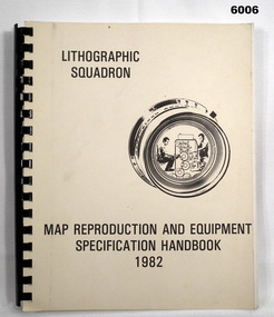
Manual - Map Reproduction and Equipment Specification Handbook, 1982
This handbook provided comprehensive technical information principally to the lithographic technician and to other Royal Australian Survey Corps technical trades. Part 1 comprised technical descriptions and photos of lithographic equipment used in military map production. Part 2 provided various tables such as printing sizes conversion tables. Part 3 provided technical guidance on the stipples and screens utilised in the map reproduction process. Part 4 detailed the Pantone Matching System printing colours for map and chart products. Part 5 was a Glossary of Lithographic Technical Terms.Army Survey Regiment Manual/handbook with a manilla cover comprising approximately 100 pages. The pages in the document are in black and white paper providing technical information and photograph identifying lithographic equipment and other information to lithographic technicians. Printed on standard paper bound by a by a black plastic spiral spline.royal australian survey corps, rasvy, fortuna, army svy regt, asr, army survey regiment -
 Flagstaff Hill Maritime Museum and Village
Equipment - Dentist Drill, Late 19th century
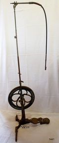
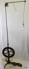
The design of this and other similar treadle powered dental engine (or dentist drill) was in common use by dentists from the 1870’s into the 1920's. When electricity became accessible to most communities the electrically powered dental engines began to take over from the treadle power. Over the ages teeth were extracted using picks and scissors and other gouging instruments. Bow drills, hand drills and even a "bur thimble" drill were later used to prepare cavities for filling. Some drills were made bendable by attaching flexible shanks between the metal bur and the handle, giving access to the teeth at the back of the mouth. Other mechanical devices were introduced along the way, such as clockwork drills, but they were hard to handle and inefficient. Over the centuries “dentistry has been performed by priests, monks and other healers. This was followed by barbers; the barber’s chair may well have been the precursor to the dental chair. “(SA Medical Heritage Society Inc.) In 1871 James Morrison patented the first commercially manufactured 'foot treadle dental engine', the first practica dental engine although others had been introduced as early as 1790 (by John Greenwood). Handmade steel burs or drills were introduced for dental handpieces, taking advantage of the significant increase in the speed of the drill. In 1891 the first machine-made steel burs were in use. The treadle drill reduced the time to prepare a cavity from hours to less than ten minutes. In 1876 the Samuel S. White Catalogue of Dentist Instruments listed a 12 ½ inch wheel diameter dental engine, with 14 bright steel parts, for sale at US $55 In today’s market, this is the equivalent to US $1200 approx. The specifications of that dental engine are very similar to the this one in our Flagstaff Hill Maritime Village’s collection. It is interesting to note that workings of a similar treadle dentist drill were used and modified to power a treadle spinning wheel of one of the volunteer spinners at Flagstaff Hill Maritime Village. The foot treadle dental engine was a milestone in dental history. “Historic importance of treadle powered machines; they made use of human power in an optimal way” (Lowtech Magazine “Short history of early pedal powered machines”) The invention of a machine to speed up the process of excavation of a tooth lead to the invention of new burs and drills for the handpieces, improving speed and the surgical process of dentistry. They were the fore-runner of today’s electrically powered dental engines. This treadle-powered dentist drill, or dentist engine, is made of iron and steel and provides power for a mechanical dental hand-piece that would be fitted with a dental tool. The drill has a three footed cast iron base, one foot being longer than the other two. A vertical C shaped frame is joined into the centre of the base, holding an axle that has a driving-wheel (or flywheel) and connecting to a crank. A slender, shoulder height post, made from telescoping pipes, joins into the top of this frame and is height adjusted by a hand tightened screw with a round knob. On the post just above the frame is a short metal, horizontal bar (to hold the hand-piece when it is not in use). A narrow tubular arm is attached to the top of the stand at a right angle and can move up and down. At the end of the arm is a firmly fixed, flexible rubber hose protected for a short distance by a sheath of thin metal. At the end of the hose there is a fitting where the drill’s hand-piece would be attached; a small, silver coloured alligator clip is also at the end. A treadle, or foot pedal, is hinged to the heel to the long foot of the base, and joined at the toe to the crank that turns the driving-wheel. There is a spring under the toe of the treadle. The metal driving-wheel has a wide rim. Touching the inside of the rim are four tubular rings that bulge towards the outside of the driving-wheel, away from the pole, and all meet at the hub of the axle. The axle is bulbous between the inside of the driving-wheel and the frame then passes through the frame and is attached on the other side. The driving-wheel has a groove around which a belt would sit. The belt would also fit around a pulley on the arm, at the top of the post. The pulley is joined to a rod inside the arm and this spins the drill's hand-piece and dental tool holder. The two shorter feet of the base are made from a long metal bar that has been curved outwards, and its centre is bolted to the base of the pole. Under the ends of the curved legs of the base are wedge shaped feet. The driving-wheel is decorated in light coloured paint on both sides, each side having three sets of floral decals evenly spaced around them, and each about a sixth of the wheel's circumference. Similar decoration is along the sides of the frame. The foot pedal has decorative cutout patterns in the centre of the foot and at the toe. On the long foot of the stand is some lettering with a fine, light coloured border around it. The lettering is hard to read, being a dark colour and flaking off. There are also remnants of fine, light coloured flourishes. The foot pedal has lettering of the maker’s trade mark cast into the metal at the ball of the foot. Lettering on the base is peeling and difficult to read. The foot pedal has a trade mark cast into it that looks like a combination of ‘C’ , ‘S’ , ‘A’, ‘R’. flagstaff hill, warrnambool, shipwrecked coast, flagstaff hill maritime museum, maritime museum, shipwreck coast, flagstaff hill maritime village, great ocean road, dentist, teeth, dental drill, dental engine, treadle drill, foot powered drill, treadle engine, orthodontics, dental surgery, james morrison -
 Flagstaff Hill Maritime Museum and Village
Equipment - Dentist Drill, Late 19th century
The design of this and other similar treadle powered dental engine (or dentist drill) was in common use by dentists from the 1870’s into the 1920's. When electricity became accessible to most communities the electrically powered dental engines began to take over from the treadle power. Over the ages teeth were extracted using picks and scissors and other gouging instruments. Bow drills, hand drills and even a "bur thimble" drill were later used to prepare cavities for filling. Some drills were made bendable by attaching flexible shanks between the metal bur and the handle, giving access to the teeth at the back of the mouth. Other mechanical devices were introduced along the way, such as clockwork drills, but they were hard to handle and inefficient. Over the centuries “dentistry has been performed by priests, monks and other healers. This was followed by barbers; the barber’s chair may well have been the precursor to the dental chair. “(SA Medical Heritage Society Inc.) In 1871 James Morrison patented the first commercially manufactured 'foot treadle dental engine', the first practica dental engine although others had been introduced as early as 1790 (by John Greenwood). Handmade steel burs or drills were introduced for dental handpieces, taking advantage of the significant increase in the speed of the drill. In 1891 the first machine-made steel burs were in use. The treadle drill reduced the time to prepare a cavity from hours to less than ten minutes. In 1876 the Samuel S. White Catalogue of Dentist Instruments listed a 12 ½ inch wheel diameter dental engine, with 14 bright steel parts, for sale at US $55 In today’s market, this is the equivalent to US $1200 approx. The specifications of that dental engine are very similar to the this one in our Flagstaff Hill Maritime Village’s collection. It is interesting to note that workings of a similar treadle dentist drill were used and modified to power a treadle spinning wheel of one of the volunteer spinners at Flagstaff Hill Maritime Village. The foot treadle dental engine was a milestone in dental history. “Historic importance of treadle powered machines; they made use of human power in an optimal way” (Lowtech Magazine “Short history of early pedal powered machines”) The invention of a machine to speed up the process of excavation of a tooth lead to the invention of new burs and drills for the handpieces, improving speed and the surgical process of dentistry. They were the fore-runner of today’s electrically powered dental engines. This treadle-powered dentist drill, or dentist engine, is made of iron and steel and provides power for a mechanical dental handpiece that would be fitted with a dental tool. On the foot is painted lettering naming it "The Brentfield" and there is a fine line of light coloured paint creating a border around the name. The paint under the lettering is peeling off. The drill has a Y-shaped, three footed cast iron base, one foot being longer than the other two. A vertical frame is joined into the centre of the base, holding an axle that has a driving-wheel (or flywheel) and connecting to a crank. A slender, shoulder height post, made from adjustable telescoping pipes, joins into the top of this frame. On the post just above the frame is a short metal, horizontal bar (to hold the hand-piece when it is not in use). A narrow tubular arm is attached to the top of the stand at a right angle and can move up, down and around. There is a pulley each side of the joint of the arm and a short way along the arm is fitted a short metal pipe. A little further along the arm a frayed-ended cord hangs down from a hole. At the end of the arm is another pulley and a joint from which hangs a long, thin metal pipe with two pulleys and a fitting on the end. A treadle, or foot pedal, is joined to the long foot of the base, and joined at the toe to the crank that turns the driving-wheel. The metal driving-wheel has a wide rim. Touching the inside of the rim are four tubular rings that bulge towards the outside of the driving-wheel, away from the pole, and all meet at the hub of the axle. The axle fits between the inside of the driving-wheel and the frame then passes through the frame and is attached on the other side. The driving-wheel has a groove around which a belt would sit. The belt would also fit around a pulley on the arm, at the top of the post. The pulley is joined to a rod inside the arm and this spins the drill's hand-piece and dental tool holder. The foot pedal has a cross-hatch pattern on the heel and the ball of the foot has tread lines across it. The end of the toe and the instep areas have cut-out pattern in them. "The ____/ Brentfield / __ DE IN L___" (Made in London) painted on the long foot of the base. Marked on the drill connection is “Richter De Trey, Germany”flagstaff hill, warrnambool, shipwrecked coast, flagstaff hill maritime museum, maritime museum, shipwreck coast, flagstaff hill maritime village, great ocean road, dentist, teeth, dental drill, dental engine, treadle drill, foot powered drill, treadle engine, orthodontics, dental surgery, james morrison, the brentfield, richter de trey, german dental fitting, london dental drill -
 Flagstaff Hill Maritime Museum and Village
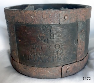
Functional object - Dry Measurement Container, Late 18th to early 19th century (before the standardised measurement was introduced in England in 1824)
The peck has been in use since the early 14th century when it was introduced as a measure for flour. The term referred to varying quantities until the modern units of measurement were defined in the 19th century. Cities in England used to have official standard weights and measures for that city or area. These containers were marked with the city's name and emblem, merchant’s weights and measures would then be checked against this to make sure they weren't trying to cheat their customers. The item in the collection is a standard measure approved by Bristol City and used by that City’s grocers to measure dry goods such as peas, beans, sugar, flour, meal etc., and its metal banding ensures that the measure cannot be reduced in size to cheat customers. Additional Information: The British Imperial System evolved from the thousands of Roman, Celtic, Anglo-Saxon, and customary local units employed in the middle Ages. Traditional names such as pound, foot, and gallon were widely used, but the values so designated varied with time, place, trade, product specifications, and dozens of other requirements. Early royal standards were established to enforce uniformity took the name Winchester, after the ancient tenth century capital of Britain. King Henry VII reaffirmed the customary Winchester standards for capacity and length and distributed royal standards throughout the realm. This process was repeated about a century later in the reign of Queen Elizabeth I. In the 16th century, the rod (5.5 yards, or 16.5 feet) was defined (once again as a learning device and not as a standard) defined by the length of the left feet of 16 men lined up heel to toe as they emerged from the church. By the 17th century usage and legal statute had established the acre, rod, and furlong at their present values together with other historic units such as the peck. Establishment of the System: The Weights and Measures Act of 1824 and the Act of 1878 established the British Imperial System based on precise definitions of selected existing units. The 1824 act sanctioned a single imperial gallon to replace the wine, ale, and corn (wheat) gallons that were in general use. The new gallon was defined as equal in volume to 10 pounds avoirdupois of distilled water weighed at 62°F with the barometer at 30 inches, or 277.274 cubic inches (later corrected to 277.421 cubic inches). The two new basic standard units were the imperial standard yard and the troy pound, which was later restricted to weighing drugs, precious metals, and jewels. In 1963 an act of parliament abolished archaic measures as the rod and chaldron and a metric system was adopted. An early example of a dry measuring container giving a snapshot of how imperial weights and measures developed in England to evolve the British measurement system into the metric arrangement that most countries have adopted today including Australia. It has social significance as an item that was in everyday use by grocers and other merchants to measure dry goods in the late 18th to early 19th centuries and used specifically in the Bristol region of England as an officially recognised measurement.Wooden measurement container with iron banding and hand made rivets container is a Quarter Peck official measurement container. Inscriptions are impressed into the sides of the wooden body. The container has the official crown and emblem of the City of Bristol, indicating this item was the Bristol City standard quarter peck measurement.Impressed into the timber on the front, a crown emblem over "C B G / CITY OF BRISTOL / QUARTER", on one side "HALF" , another side "PECK". Handwritten in white chalk on the base is "1458"flagstaff hill, warrnambool, shipwrecked-coast, flagstaff-hill-maritime-museum, flagstaff-hill-maritime-village, weights and measures, quarter peck, measurement container, dry grocery measure, bristol city measurement standard, city of bristol, british weights and measures, 18th and 19th centure standard measures -
National Wool Museum
Record Sheet
... 4 daily record sheets with specifications about specific...-and-the-bellarine-peninsula 4 daily record sheets with specifications about ...4 daily record sheets with specifications about specific mill processes.textile mills -
Moorabbin Air Museum
Manual (Item) - Sioux Centrifugal Clutch Shoes - Liner Bonding Process RAAF Specification Engineering, Sioux Centrifugal Clutch Shoes - Liner Bonding Process
... Sioux Centrifugal Clutch Shoes - Liner Bonding Process RAAF... Process RAAF Specification Engineering ... -
Moorabbin Air Museum
Document (item) - RAAF Specification Engineering Number I5004 Issue Number 1 - Installation Of AQS-9014 Sonics Processor And Ancillary Modifications Into P3C Aircraft
-
 Falls Creek Historical Society
Letter - Copies Of Mislaid Letters Will Not Be Supplied
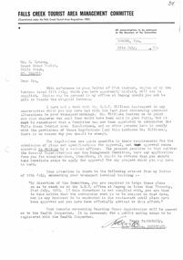
Bob Hymans Collection Bob (Herman) Hymans (a former member of the Royal Netherlands Navy) was born in Bloemendaal, Holland on 30th September 1922. During World War II he fought against the Japanese in the Dutch East Indies (now Indonesia) and was imprisoned in Changi and on the Burma Railway. After gaining qualifications as a Ski Instructor, Bob arrived in Falls Creek in July 1950. Working as an Instructor and Supervisor at Bogong Lodge, Bob decided his future was in accommodation. He was successful in negotiating an indenture for land from the State Electricity Commission (SEC). It took Bob two years to build his Grand Coeur Chalet but, tragically, it was burned down in August 1961. Bob also built the first Chairlift in Australia. This was a single chairlift and the structure was built from wooden electricity poles. He was constantly full of new ideas and proposals for the village. Bob Hymans died on 7th July 2007. This Collection of documents and letters tells the story of Bob's endeavours to develop Falls Creek into the ski village it is today.This letter is significant because it reflects the relationship between Bob Hymans and the Management Committee.A letter from the Management Committee stating that requested copies of lost registered letters would not be supplied. They could be viewed in the office at Bogong. The communication also strongly stated that regarding alterations to Mr Hymans' transport terminal, Regulations set out specific requirements for the submission of plans and specifications. There was no reason why Hymans should be exempt from this process.falls creek tourist area management committee, bob hymans -
 Melbourne Tram Museum
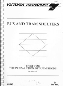
Document - Report, Minister of Transport, "Bus and Tram Shelters - Brief for the Preparation of Submissions", Dec. 1989
Document titled "Bus and Tram Shelters - Brief for the Preparation of Submissions" Issued by the Ministry for Transport, Victoria Transport, December 1989. Has a table of contents. Asks for submissions for shelters at tram and bus stops for both V/Line and The Met. Gives an outline of the project, selection process, information required in the submission, advertising proposals, design requirements. Has a number of drawings including "The Met" logo in large format.Part of the design process for a new style of bus / tram shelter in Melbourne.Report or Specification or brief, approx. 70 pages, white comb bound, clear plastic front cover, white rear card cover.In ink on the top right hand corner "1989", and on bottom edge "3.07m / 43"trams, tramways, ptc, the met, bus stops, shelters, v/line, advertisements -
 Melbourne Tram Museum
book - Engineering Standards, Standards Association of Australia, "E30 - 1934 - Australian Standards Specification for Manganese Steel Castings for Tramway Trackwork", 1934
Set of two Engineering Standards stapled within in a Standards Association of Australia folder" with the numbers stamped and hand written onto the cover. Contains 6 sheets printed using the Gestetner process and one photocopy on foolscap paper. Contains the standards for "E30 - 1934 - Australian Standards Specification for Manganese Steel Castings for Tramway Trackwork"in ink "1939" and "Hardwood Paving Blocks" on right hand edge.trams, tramways, standards, track materials, track repairs, road works, points, trackwork -
 Bendigo Military Museum
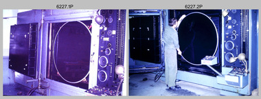
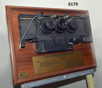
Plaque - Mounted Klimsch Commodore Cartographic Camera Lenses, WYCOMBE Constructions Pty Ltd, 1997
These are the Lenses from the Klimsch Commodore Cartographic Camera that was located in Lithographic Squadron at the Army Survey Regiment, Fortuna, Bendigo. The KLIMSCH Commodore camera was originally introduced to the Survey Regiment in 1953 and was the largest in the Southern Hemisphere. It was replaced with a new model of the same size in 1977. These lenses are from this new model. The new model with its computer-based interface provided productivity gains with improved speed and its consistent results led to less wastage in time and materials. Its variomat lens system provided improved retention of map feature linear weights during the camera reduction process. The camera which was specially made for the Australian Army in Germany was fully automatic and power operated. It was claimed to be one of the biggest automatic cameras of its type in the world. It was made to the specifications of the Royal Australian Army Survey Corps to assist in the production of the very high standard maps for the Australian Army. THIS KLIMSCH COMMODORE CARTOGRAPHIC CAMERA was in operation 1977 - 1997". It was a Precision Darkroom Camera especially suited for Cartographic Reproduction of Line, Continous Tone, Halftone and Colour Separation. Reproduction of Negatives and Positives from a variety of Reflection or Transmission Originals. Its characteristics were: Maximum Negative Size 1.27m sq, Copy Holder (Vacuum) 2m sq, Maximum Enlargement 400%, Maximum Reduction 13%, Automatic 60, 90 and 120cm Focal Length Lens, Transmission or Reflection Originals, Pulsed Xenon, Photo Flood or Fluorescent Tube Light Source, Maximum Reflection Original 1.3m x 1.85m, Maximum Transmission Original 1.3m x 1.85m, Exposure Light Monitoring System." The camera was superseded by computerized image manipulation software associated with the Automap system. These significant and extremely high-quality Lenses were retrieved by WYCOMBE Constructions Pty Ltd during the demolishment of the camera in 1997 and then mounted on a display board. See also Item 6189.4P for more photographs of the camera.Lenses from the Klimsch Commodore Cartographic Camera mounted on a very heavy timber display board. The display board contains an engraved plate that describes the technical characteristics of the camera."KLIMSCH COMMODORE CARTOGRAPHIC CAMERA 1977 - 1997", "FUNCTION: Precision Darkroom Camera especially suited for Cartographic Reproduction of Line, Continous Tone, Halftone and Colour Separation. Reproduction of Negatives and Positives from a variety of Reflection or Transmission Originals." "CHARACTERISTICS: Maximum Neg Size 1.27m sq, Copy Holder 2m sq, Maximum Enlargement 400%, Maximum Reduction 13%, Automatic 60, 90, 120cm Focal Length Lens, Transmission or Reflection Originals, Pulsed Xenon, Photo Flood or Fluorescent Tube Light Source, Maximum Reflection Original 1.3m x 1.85m, Maximum Transmission Original 1.3m x 1.85m, Exposure Light Monitoring System." royal australian survey corps, rasvy, fortuna, army survey regiment, army svy regt, asr, litho