

Historical information
The design of this and other similar treadle powered dental engine (or dentist drill) was in common use by dentists from the 1870’s into the 1920's. When electricity became accessible to most communities the electrically powered dental engines began to take over from the treadle power.
Over the ages teeth were extracted using picks and scissors and other gouging instruments. Bow drills, hand drills and even a "bur thimble" drill were later used to prepare cavities for filling. Some drills were made bendable by attaching flexible shanks between the metal bur and the handle, giving access to the teeth at the back of the mouth. Other mechanical devices were introduced along the way, such as clockwork drills, but they were hard to handle and inefficient. Over the centuries “dentistry has been performed by priests, monks and other healers. This was followed by barbers; the barber’s chair may well have been the precursor to the dental chair. “(SA Medical Heritage Society Inc.)
In 1871 James Morrison patented the first commercially manufactured 'foot treadle dental engine', the first practica dental engine although others had been introduced as early as 1790 (by John Greenwood). Handmade steel burs or drills were introduced for dental handpieces, taking advantage of the significant increase in the speed of the drill. In 1891 the first machine-made steel burs were in use. The treadle drill reduced the time to prepare a cavity from hours to less than ten minutes.
In 1876 the Samuel S. White Catalogue of Dentist Instruments listed a 12 ½ inch wheel diameter dental engine, with 14 bright steel parts, for sale at US $55 In today’s market, this is the equivalent to US $1200 approx. The specifications of that dental engine are very similar to the this one in our Flagstaff Hill Maritime Village’s collection.
It is interesting to note that workings of a similar treadle dentist drill were used and modified to power a treadle spinning wheel of one of the volunteer spinners at Flagstaff Hill Maritime Village.
Significance
The foot treadle dental engine was a milestone in dental history. “Historic importance of treadle powered machines; they made use of human power in an optimal way” (Lowtech Magazine “Short history of early pedal powered machines”)
The invention of a machine to speed up the process of excavation of a tooth lead to the invention of new burs and drills for the handpieces, improving speed and the surgical process of dentistry. They were the fore-runner of today’s electrically powered dental engines.
Physical description
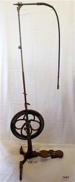
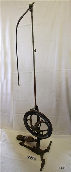
This treadle-powered dentist drill, or dentist engine, is made of iron and steel and provides power for a mechanical dental hand-piece that would be fitted with a dental tool.
The drill has a three footed cast iron base, one foot being longer than the other two. A vertical C shaped frame is joined into the centre of the base, holding an axle that has a driving-wheel (or flywheel) and connecting to a crank. A slender, shoulder height post, made from telescoping pipes, joins into the top of this frame and is height adjusted by a hand tightened screw with a round knob. On the post just above the frame is a short metal, horizontal bar (to hold the hand-piece when it is not in use).
A narrow tubular arm is attached to the top of the stand at a right angle and can move up and down. At the end of the arm is a firmly fixed, flexible rubber hose protected for a short distance by a sheath of thin metal. At the end of the hose there is a fitting where the drill’s hand-piece would be attached; a small, silver coloured alligator clip is also at the end.
A treadle, or foot pedal, is hinged to the heel to the long foot of the base, and joined at the toe to the crank that turns the driving-wheel. There is a spring under the toe of the treadle.
The metal driving-wheel has a wide rim. Touching the inside of the rim are four tubular rings that bulge towards the outside of the driving-wheel, away from the pole, and all meet at the hub of the axle. The axle is bulbous between the inside of the driving-wheel and the frame then passes through the frame and is attached on the other side. The driving-wheel has a groove around which a belt would sit. The belt would also fit around a pulley on the arm, at the top of the post. The pulley is joined to a rod inside the arm and this spins the drill's hand-piece and dental tool holder.
The two shorter feet of the base are made from a long metal bar that has been curved outwards, and its centre is bolted to the base of the pole. Under the ends of the curved legs of the base are wedge shaped feet.
The driving-wheel is decorated in light coloured paint on both sides, each side having three sets of floral decals evenly spaced around them, and each about a sixth of the wheel's circumference. Similar decoration is along the sides of the frame. The foot pedal has decorative cutout patterns in the centre of the foot and at the toe.
On the long foot of the stand is some lettering with a fine, light coloured border around it. The lettering is hard to read, being a dark colour and flaking off. There are also remnants of fine, light coloured flourishes. The foot pedal has lettering of the maker’s trade mark cast into the metal at the ball of the foot.
Inscriptions & markings
Lettering on the base is peeling and difficult to read.
The foot pedal has a trade mark cast into it that looks like a combination of ‘C’ , ‘S’ , ‘A’, ‘R’.
Subjects
- flagstaff hill,
- warrnambool,
- shipwrecked coast,
- flagstaff hill maritime museum,
- maritime museum,
- shipwreck coast,
- flagstaff hill maritime village,
- great ocean road,
- dentist,
- teeth,
- dental drill,
- dental engine,
- treadle drill,
- foot powered drill,
- treadle engine,
- orthodontics,
- dental surgery,
- james morrison