
Showing 13 items matching "the vertical component"
-
 Moorabbin Air Museum
Book - Indian Air Force, The Indian Air Force and its Aircraft
... ...The vertical component...Indian Air Force Fifty years on ..the Indian Air Force today Sepecat Jaguar profile HAL aircraft IAF Mig 21s Air bridge The vertical component Training in the IAF Indian Air Force half century Canberras Overview & technical specifications of aircraft used by Indian Air Force 1932 to 1982 The Indian Air Force and its Aircraft Book Indian Air Force ...Overview & technical specifications of aircraft used by Indian Air Force 1932 to 1982non-fictionOverview & technical specifications of aircraft used by Indian Air Force 1932 to 1982fifty years on ..the indian air force today, sepecat jaguar profile, hal aircraft, iaf mig 21s, air bridge, the vertical component, training in the iaf, indian air force half century, canberras -
 Federation University Art Collection
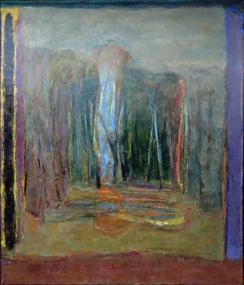
Painting - Artwork, Wright, Doug, 'The Seasons - Mt Helen' by Doug Wright, 1993
... Abstract landscape with vertical lineal components....The Art Collection features over 2000 works and was listed as a 'Ballarat Treasure' in 2007. art artwork doug wright landscape Abstract landscape with vertical lineal components. 'The Seasons - Mt Helen' by Doug Wright Painting Artwork Wright, Doug ...Doug WRIGHT (1944 - ) Born Ballarat Doug Wright studied at the Ballarta School of Mines Art School between 1963 and 1964, followed by studies at the Royal Melbourne Institute of Technology from 1965 to 1966, resulting in a Diploma of Art (Fine Art Painting). Since 1974 Doug Wright has had over 20 solo exhibitions and a survey exhibition in 1993 which travelled Victorian Regional Galleries. From 1975 to 2009 Doug Wright was Lecturer in Painting at State College of Victoria (Ballarat) and University of Ballarat. This item was commissioned for the entrance of the new Administration Building at Mount Helen by the Director of Ballarat University College, is part of the Federation University Art Collection. The Art Collection features over 2000 works and was listed as a 'Ballarat Treasure' in 2007.Abstract landscape with vertical lineal components.art, artwork, doug wright, landscape -
 Geoffrey Kaye Museum of Anaesthetic History
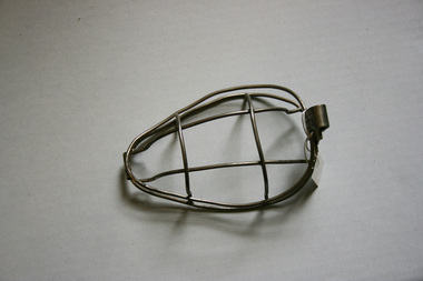
Equipment - Bellamy Gardner mask, 1908
... The wire-framed dome has both vertical and horizontal wire components to sit over a patient's nose and mouth. ...The wire-framed dome has both vertical and horizontal wire components to sit over a patient's nose and mouth. ...H. Bellamy Gardner, an anaesthetist at the Charing Cross Hospital, was the first to use open ether in England and was responsible for popularizing the technique. Bellamy Gardner's mask consists of a wire frame which was covered with layers of gauze. He recommended constructing a face-pad consisting of several layers of gauze which were rolled together and tied to make an oval. This was applied to the face and the mask rested on the top. Ether was then administered directly on to the mask.Oval chrome-plated steel wire frame designed to fit around a face. The wire-framed dome has both vertical and horizontal wire components to sit over a patient's nose and mouth. Ether was applied to a gauze pad which was held securely in place by a hinged wire lid. This is a modified version of Bellamy Gardner's original mask.Etched on clasp: BELLAMY / GARDNER'S / ETHER MASKether, gauze -
 Orbost & District Historical Society
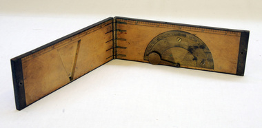
clinometer rule, mid 19th -earl 20th century
... vertical angles. It is used to measure the angle of elevation from the ground in a right-angled triangle. It may have been used by a surveyor or a forester to measure the height of tall things where you couldn't possibly reach to the top of e.g. flag poles, buildings or trees. This item is an example of an early hand held measuring instrument.. Today the use of electronic sensors is an important component ...This clinometer, is a hand-held optical scientific instrument used in surveying to measure vertical angles. It is used to measure the angle of elevation from the ground in a right-angled triangle. It may have been used by a surveyor or a forester to measure the height of tall things where you couldn't possibly reach to the top of e.g. flag poles, buildings or trees.This item is an example of an early hand held measuring instrument.. Today the use of electronic sensors is an important component in the design and function of the clinometers.A rectangular wooden folding measuring instrument. the panels are brass framed. Inside is a brass semi-protractorgraduated 90-0-90' with index arm pointeran dwith a graduated edge in inches. Outside is a temperature conversion scale,Troughton & Simms, LONDONscientific-instrument measurement clinometer -
 Warrnambool RSL Sub Branch
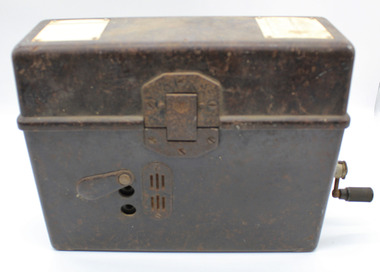
WW2 Field Telephone/Communication Instrument; German
... vertically aligned 85mm from left, 25mm apart either side of mid point of height of bodyprotedted by protective pivot plate. Air vent plate attached with 2 screws adjacent to Jack plug holes (same on Back). Left side at top; metal plate for carry strap (same on right side). carry strap not with item.Right side; hole covered by protective cover plate centred 70mm from base , Wind-Up handle attached (described seoarately. Body Inside: 2/3 filled with visible metal and bakelite components...vertically aligned 85mm from left, 25mm apart either side of mid point of height of bodyprotedted by protective pivot plate. Air vent plate attached with 2 screws adjacent to Jack plug holes (same on Back). Left side at top; metal plate for carry strap (same on right side). carry strap not with item.Right side; hole covered by protective cover plate centred 70mm from base , Wind-Up handle attached (described seoarately. Body Inside: 2/3 filled with visible metal and bakelite components ...Used in WW2. Basically of german origin and manufacture but 'English' handset suggests capture and use by Australian forces possibly in Middle East Desert warfare.Black Rectangular Metal Box with Lid. Total Height 215mm (with lid closed), Body Height 140mm. Lid Height 75mm.Lid attached by full length Hinge on rear and locking Clip at front.Depth 90mm. Length 275mm. Lid Outside: has overlapping lip to body when closed.Reinforcing metal attachment on left side rolls over to inside of lid and is attached by two screws. Front locking clip is spring loaded and attached to lid by 3 screws. Lid Inside: Flexible metal plate to clip on handset. 2 inscription plates on left and right ends and telephone handset described separately Body Outside:Front: 2 Jack plug points, vertically aligned 85mm from left, 25mm apart either side of mid point of height of bodyprotedted by protective pivot plate. Air vent plate attached with 2 screws adjacent to Jack plug holes (same on Back). Left side at top; metal plate for carry strap (same on right side). carry strap not with item.Right side; hole covered by protective cover plate centred 70mm from base , Wind-Up handle attached (described seoarately. Body Inside: 2/3 filled with visible metal and bakelite components in separate compartment containing unseen working parts. Left side contains morse code key in canvas bag (described separately). Contents Inside Lid. Two schematics of wiring layouts attached to left and right ends. Removable Bakelite handset clipped into postion for carrying, attached cable has 4-pronged attachment connected to main section in body. Contents Inside Body. Most working parts hidden inside metal container. White plastic button 'Pruttaste' is a test button; threaded screws on top for attachments not present.Two pieces of loose wire purpose unknown. Canvas Bag with zip, labelled DD with arrow between (Department of Defence) containing Morse Code Key; wire with large jackplug attachment connected to MC Key through the bag. Jackplug connects via front of body of object. The whole of this item is stored in left inside of body.underside of handset says PRESS KEY WHILE SPEAKING and in smaller font size TELE HD NO 2 -
 Geoffrey Kaye Museum of Anaesthetic History
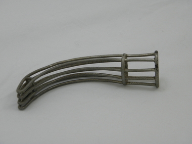
Equipment - Mayo's Airway, Down Bros
... The long, circular-shaped metal components are moulded to create an 'open bar' system which resemble the vertical bars of a cage....The long, circular-shaped metal components are moulded to create an 'open bar' system which resemble the vertical bars of a cage. ...Tubular airway with ovoid opening and curved terminal point to allow access to the patient's airway. The long, circular-shaped metal components are moulded to create an 'open bar' system which resemble the vertical bars of a cage.The manufacturer's details, 'DOWN BROS. LONDON', are stamped on the opening rim of the airwayairway, mayo, down bros london, anaesthesia, nickel, ovoid -
 Geoffrey Kaye Museum of Anaesthetic History
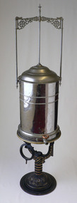
Equipment - Nitrous oxide gasometer, Buffalo Dental Manufacturing Company, 1876-1901
... Inscription on vertical. "1 2 3" Inscription on upper side of top ring. "J. DEMAREST//PAT.FEB.15.1876." Inscription on lower side of top ring. "15" The main component of the nitrous oxide gasometer is a reflective white metal urn-shaped chamber from which an outlet valve and circular moulded tap allows for the flow of gas. ...The main component of the nitrous oxide gasometer is a reflective white metal urn-shaped chamber from which an outlet valve and circular moulded tap allows for the flow of gas. A rectangular frame sits atop the chamber and comprises ornately decorated metal flourishes and three white metal anchoring pipes, two attached to each side of the chamber and one attached to the centre of the two-tiered, domed lid. The gasometer sits atop a Y-shaped cast iron stand, ornately decorated with metallic golden brass paint, with a circular base. There is also a black cast iron ring that is attached to the stand. Manufactured by Buffalo Dental Manufacturing Company, Buffalo NY.Inscription on base. "B.D.M. CO, BUFFALO N.Y." Inscription on vertical. "1 2 3" Inscription on upper side of top ring. "J. DEMAREST//PAT.FEB.15.1876." Inscription on lower side of top ring. "15"gasometer, nitrous oxide, storage, anaesthesia, dentistry, chloroform, ether, b.d.m. co -
 Villa Alba Museum
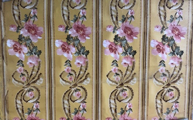
Decorative object - Wallpaper sample : Roses and bows
... components of 19th and 20th century interior decoration. These include artefacts (wallpapers, textiles, carpet samples), furnishings, printed materials (catalogues, books, periodicals), and pictures (photographs). decorative arts & design wall coverings – history wallpapers – history interior decoration – history Sections of a dado featuring a vertical design of roses and bows within bordered narrow panels. ...The Villa Alba Museum is cultural institution committed to the collection, study and display of 19th century interior decorative finishes, and the components of 19th and 20th century interior decoration. These include artefacts (wallpapers, textiles, carpet samples), furnishings, printed materials (catalogues, books, periodicals), and pictures (photographs).Sections of a dado featuring a vertical design of roses and bows within bordered narrow panels. The colourway includes shades of pink for the roses, green for the leaves, and brown for the bows, against a solid yellow background. The white of the backing paper is used within the design to create an illusion of depth in the pattern.decorative arts & design, wall coverings – history, wallpapers – history, interior decoration – history -
 Ballarat Tramway Museum
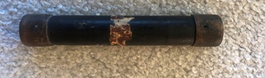
Functional Object - Tramcar component, Cartridge fuse
... Component - black Bakelite? with brass ends, possibly containing a powder given the weight and a fuse wire. Has remnants of a paper label around the centre. No details of the of the manufacturer or date. Type used for a compressor fuse. At one end has a diamond with a vertical...Component - black Bakelite? with brass ends, possibly containing a powder given the weight and a fuse wire. Has remnants of a paper label around the centre. No details of the of the manufacturer or date. Type used for a compressor fuse. At one end has a diamond with a vertical ...Cartridge fuse - Tramcar Component - black Bakelite? with brass ends, possibly containing a powder given the weight and a fuse wire. Has remnants of a paper label around the centre. No details of the of the manufacturer or date. Type used for a compressor fuse. At one end has a diamond with a vertical bar through the centre and 10 stamped into the brass end - possibly a 10Amp fuse and possibly the manufacturer's symbol.fuse, tramcars, electrical engineering, electrical equipment -
 Ballarat Tramway Museum
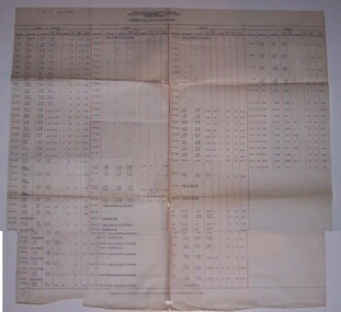
Document - Roster, State Electricity Commission of Victoria (SECV), "Motorman's Runs with daily rostered hours", 10/1946?
... vertically ruled in red ink. Not dated, but preparation format aligns with 3418 - 11/10/1946 - assume 10/1946. On rear in pencil is sketches for brake rigging components. ...vertically ruled in red ink. Not dated, but preparation format aligns with 3418 - 11/10/1946 - assume 10/1946. On rear in pencil is sketches for brake rigging components. ...Demonstrates aspects of the Ballarat Tramways following the end of the 2nd world war - when the tramway traffic was still high peak. Gives details of working hours, rosters for the week of motormen. Shows the additional trams to the basic service on Weekdays and hours of one man operation.Single large typed sheet of paper, titled SECV, Electricity Supply Department - Ballarat Branch, Ballarat Tramways, "Motorman's Runs with daily rostered hours". Arranged with four main columns, Monday to Thursday, Friday, Saturday and Sunday and within each main column 9 further columns giving Run No, Take Up, Relief times, Ord Rate (hours), One Man Rate, Spread (always "-" except for two on Saturday). Sign On and Sign Off - either 10 or 15 and the Total Hours. Columns vertically ruled in red ink. Not dated, but preparation format aligns with 3418 - 11/10/1946 - assume 10/1946. On rear in pencil is sketches for brake rigging components. In top left hand corner in black ink "B.T.P.S. Cat No. 801"trams, tramways, ballarat, rosters, employees, shifts, timetables -
 Vision Australia
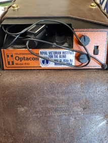
Equipment - Object, Telesensory Systems, Optacon, 1974
... vertical columns and 24 horizontal rows. Each of the rods can vibrate independently. The tips of these rods protrude through holes in a concave finger plate where the index finger is placed flat in order to read. These three components...vertical columns and 24 horizontal rows. Each of the rods can vibrate independently. The tips of these rods protrude through holes in a concave finger plate where the index finger is placed flat in order to read. These three components ...The Optacon OPtical-to-TActile-CONverter is a compact, portable reading aid for the blind. It is about the size of a textbook, and weighs less than 2kg. It works by converting a printed image into a tactile image that a blind person can feel with one finger. After a period of training and practice, a blind person can use the Optacon to read ordinary books, magazines, newspapers, and other printed materials. The Optacon was developed after intensive research at Standford University, California, USA and was trialed by clients of the Royal Victorian Institute for the Blind (now part of Vision Australia) in 1973. It has three main sections: 1 a miniature camera, 2 an electronics section, and 3 a tactile stimulator array. The miniature camera, about the size of a pocket knife, is mounted in a housing that has rollers for easy movement along a line of print. The camera is connected to the electronics section by a lightweight cable. The electronics section and the tactile stimulator array are in the main chassis. The array consists of 144 tiny metal rods arranged in six vertical columns and 24 horizontal rows. Each of the rods can vibrate independently. The tips of these rods protrude through holes in a concave finger plate where the index finger is placed flat in order to read. These three components act together to convert the image of a printed letter or other shape into a pattern of vibrating rods, a tactile image of the letter or shape. The letter shape is tactually perceived as an image that moves from right to left on the finger, showing the left or leading edge of the letter first. Letters are felt sequentially rather than all at once, and the image should be kept moving. The Optacon converts a printed O into a tactile form that resembles a crater with a vibrating rim -- a completed circle. C would have a gap or opening on the right side of the curve. The letter F would be felt, sequentially, as a vertical line with two trailing horizontal lines. Because it can convert any ordinary printed image into a corresponding tactile image, the Optacon is not restricted to any special typestyle or language. The camera has a zoom lens that compensates for differences in the size of type. The standard Optacon lens can accommodate type sizes from 6 point to 20 point. With the optional F4A magnifier lens, type sizes as small as 4 point can be read. Powered by a rechargeable battery, and comes with its own battery charger. The battery is contained within the main chassis, and is not removable by the user. There are four basic controls on the Optacon: the Magnification Adjustment zoom button located on the camera section on the side opposite the rollers; and the On-Off switch, the Stimulator Intensity Adjustment knob, and the Threshold Adjustment knob located on the right side of the front panel. The Circuit Breaker protrudes from the right-hand wall inside the chassis compartment. From left to right when the back panel is facing you, are located: the jack for connecting the battery charger; the Battery Check button; the Normal-Invert switch; and the Input/Output I/O connector for use with the Visual Display, when using the Repeater Cable to connect two Optacons to one another or with other accessories. Designed not be removed from the leather case during normal operation, the On-Off switch is a slide switch located on the right side of the front panel. It slides up and snaps into place in the on position. 1 black with orange front, rectangular device in leather case assistive devices, audio equipment -
Tarnagulla History Archive
Set of Maps (Mining & Local Area), various
... Vertical Sections of Poverty Reef, Sandy Creek 1859, by R.J. McMillan, Mining Surveyor (B&W copy) 13. Tarnagulla Locality Plan (B&W copy) 14. Universal Grid Reference Map (Topographic) for Laanecoorie North (2 copies) 15. Universal Grid Reference Map (Topographic) for Inglewood South 16. Poverty Reef, Plan showing shafts and early tenements, created by Eric WIlkinson for Ref Mining NL, 1995 17. Locality Map of mining leases in Tarnagulla 18. Plan and Elevation of part of Poverty Reef, Sandy Creek, showing the claims and positions of the shaft. by R.J. McMillan, Mining Surveyor (Facsimile, composed of taped together components...Vertical Sections of Poverty Reef, Sandy Creek 1859, by R.J. McMillan, Mining Surveyor (B&W copy) 13. Tarnagulla Locality Plan (B&W copy) 14. Universal Grid Reference Map (Topographic) for Laanecoorie North (2 copies) 15. Universal Grid Reference Map (Topographic) for Inglewood South 16. Poverty Reef, Plan showing shafts and early tenements, created by Eric WIlkinson for Ref Mining NL, 1995 17. Locality Map of mining leases in Tarnagulla 18. Plan and Elevation of part of Poverty Reef, Sandy Creek, showing the claims and positions of the shaft. by R.J. McMillan, Mining Surveyor (Facsimile, composed of taped together components ...David Gordon Collection. A set of mining documents, maps and plans: 1. Dunolly Deep Leads - showing location and names of deep lead gold deposits in region around Dunolly including at Tarnagulla and Newbridge. Geological Survey of Victoria, Department of Minerals and Energy. Bulletin No. 62, Map No. 4 Dunolly (770 x 485 mm). 2. Poseidon Lead (Facsimile) 3. Nick O Time Lead (Facsimile) 4. Happy Go Lucky Mine prospectus and plan (colour copy) 5. Jones Creek GM Co. (Raven & Gourlay's) Waanyarra - Prospectus (colour copy) 6. Poseidon Area Plan (colour copy) and Poseidon Area map (B&W copy). 7. Cross-section diagram of Spread Eagle Reef 8. New Birthday Gold Mine - area map (colour copy) and mine cross-section ( (colour copy). 9. Cross section of Poverty Reef, by Department of Mines (B&W copy, 2 parts on A2 paper) 10. Time-Lease Graph for Watts Reef, Specimen Reef, Stony Reef, Poverty Reef (second page in detail), created by Eric WIlkinson for Ref Mining NL, 1995 11. 1859 Plan of the Gold Workings & Township of Sandy Creek, Shewing the Mining Leases, Extended Claims & Machinery by R.J. McMillan, Mining Surveyor (B&W copy) 12. Longitundinal and Transverse Vertical Sections of Poverty Reef, Sandy Creek 1859, by R.J. McMillan, Mining Surveyor (B&W copy) 13. Tarnagulla Locality Plan (B&W copy) 14. Universal Grid Reference Map (Topographic) for Laanecoorie North (2 copies) 15. Universal Grid Reference Map (Topographic) for Inglewood South 16. Poverty Reef, Plan showing shafts and early tenements, created by Eric WIlkinson for Ref Mining NL, 1995 17. Locality Map of mining leases in Tarnagulla 18. Plan and Elevation of part of Poverty Reef, Sandy Creek, showing the claims and positions of the shaft. by R.J. McMillan, Mining Surveyor (Facsimile, composed of taped together components) 19.Plan and Elevation of part of Poverty Reef, Sandy Creek, showing the claims and positions of the shaft. by R.J. McMillan, Mining Surveyor (Facsimile, composed of taped together components) -
 Department of Energy, Environment and Climate Action
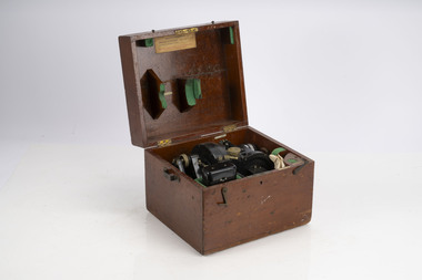
Balloon Theodolite 1943
... vertical pull of the balloon). There is some degree of control over these these factors, and as a result, it possible to know approximately how high our balloon will be at any given time after its release. Given a known height and an angular direction (read off the theodolite) to the balloon, a fix is made of the horizontal movement component of the balloon's travel as it moves through different altitudes. ...vertical pull of the balloon). There is some degree of control over these these factors, and as a result, it possible to know approximately how high our balloon will be at any given time after its release. Given a known height and an angular direction (read off the theodolite) to the balloon, a fix is made of the horizontal movement component of the balloon's travel as it moves through different altitudes. ...Used to measure the rate of rise of helium balloons The telescope is mounted on two movable axes. One axis (vertical) rotates to change elevation, the other (horizontal) azimuth. There are vernier scales and in some cases micrometres that give precise readouts of the relative position of the telescope to each axis. The instrument is set up so that it is level and it is pointed towards true north with both scales reading 0 degrees exactly. A balloon is released in front of the theodolite. It is sighted at timed intervals (usually one minute apart) and the position of the theodolite's telescope (azimuth and elevation) is recorded. It can chart the direction and velocity of winds at various altitudes The rate of ascent of a balloon is mostly dependant on the balloon's drag and its "free lift" (the vertical pull of the balloon). There is some degree of control over these these factors, and as a result, it possible to know approximately how high our balloon will be at any given time after its release. Given a known height and an angular direction (read off the theodolite) to the balloon, a fix is made of the horizontal movement component of the balloon's travel as it moves through different altitudes. The horizontal movement is due to the winds blowing the balloon around at the altitudes that the balloon is traveling throughTheodolite used to measure the rate of rising helium balloons The rate of rise is used in atmospheric calculations such as upper winds and determining inversion layersforests commission victoria (fcv), bushfire, weather
