


Historical information
Original prints - dyeline or blue prints of drawings used in W R Pollock's report on the Cable Tram System engine houses and the cable rope
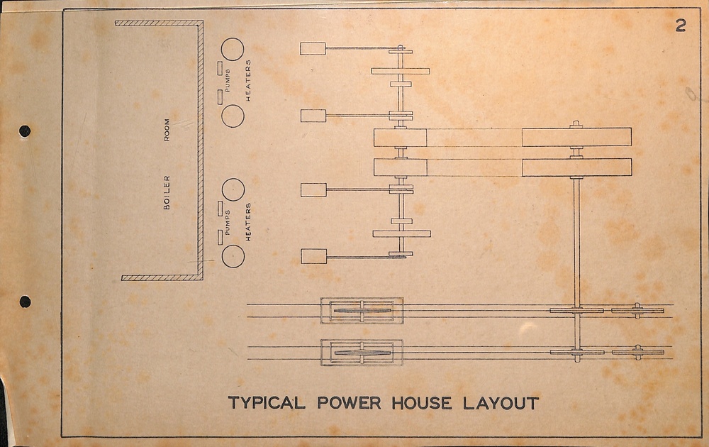
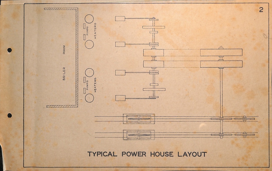
1 - Typical Power House layout
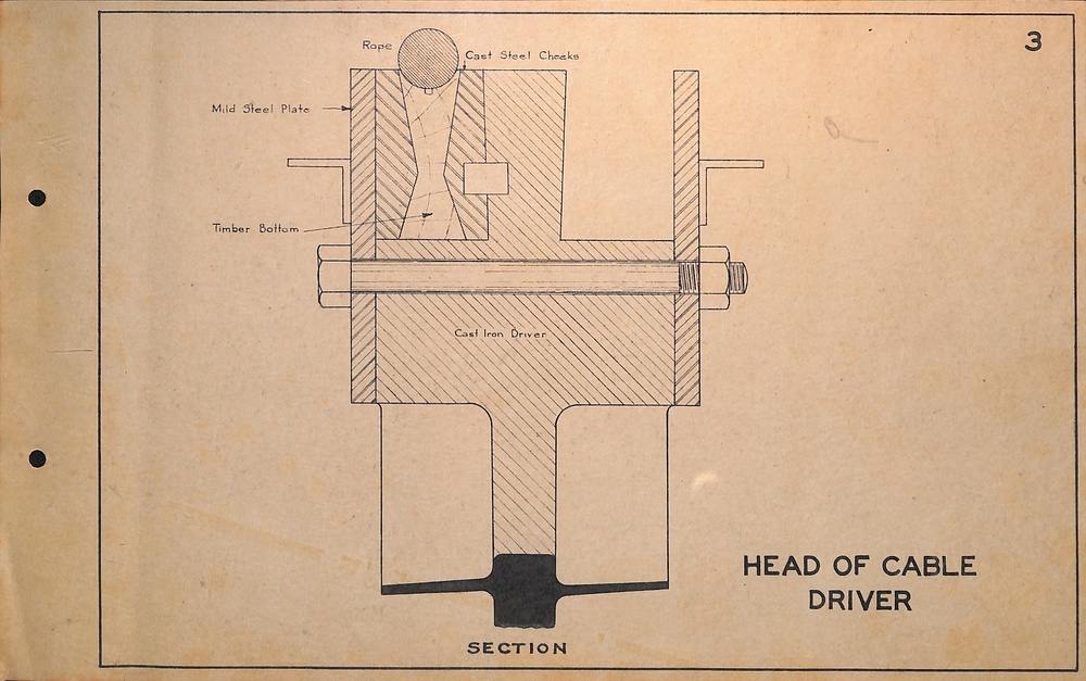
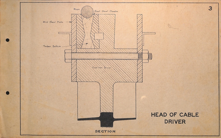
2 - Section of Cable Driver
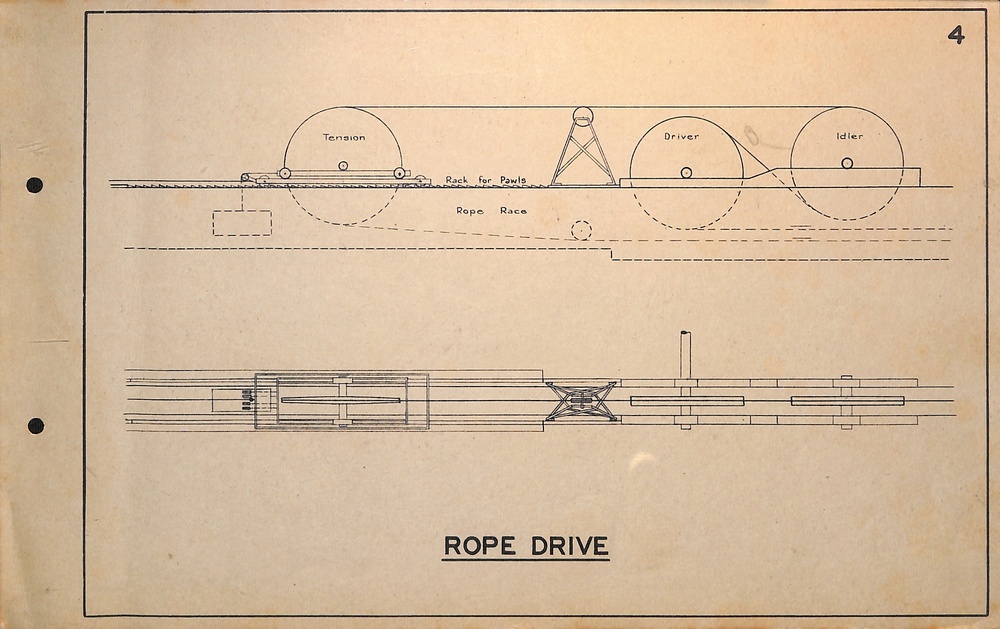
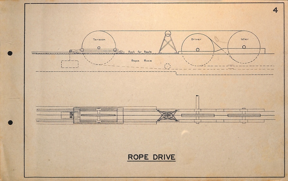
3 - Layout of rope drive
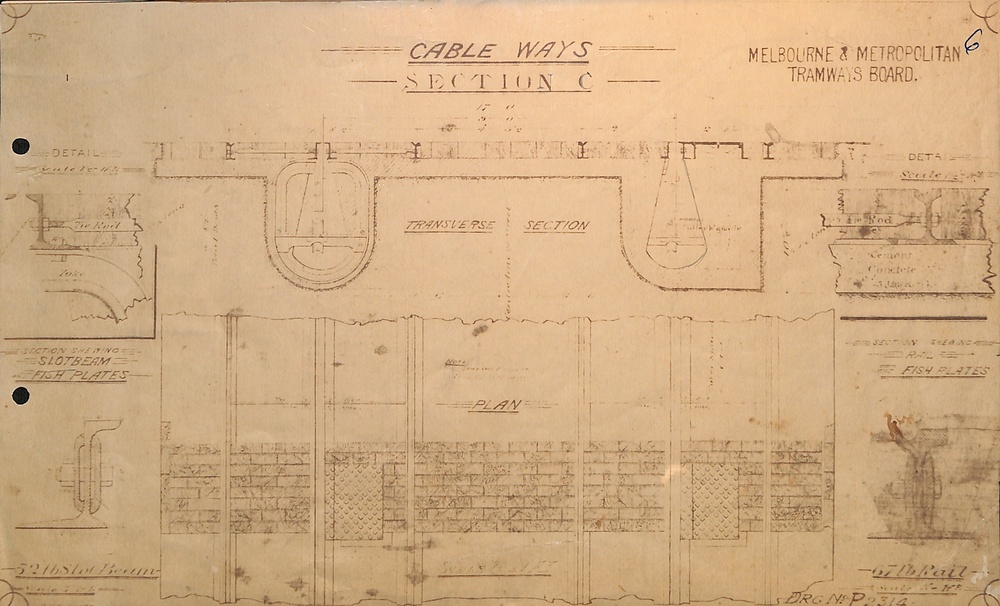
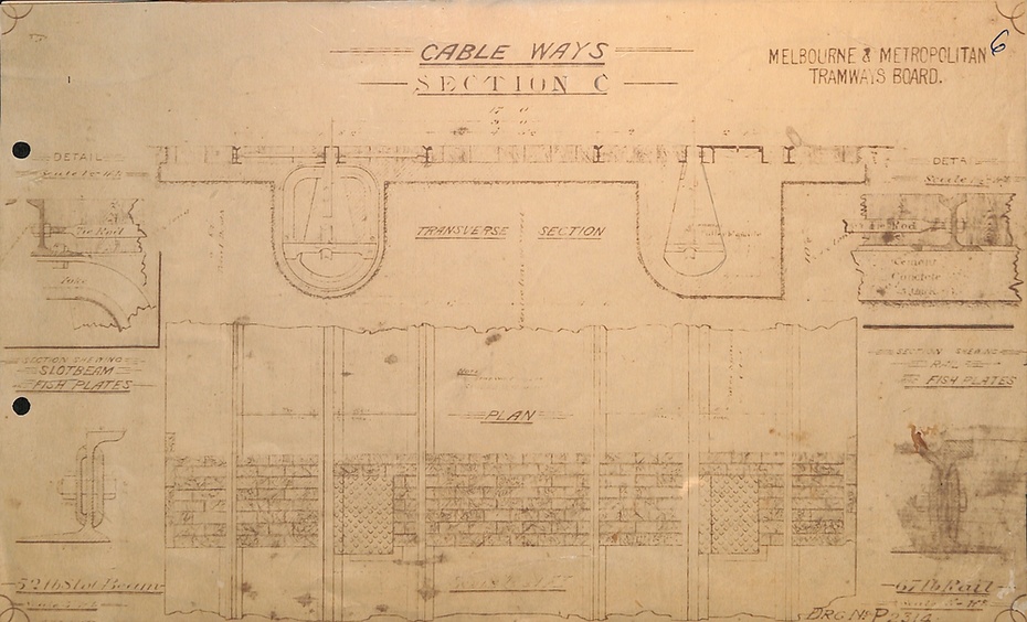
4 - Section of Cable Track
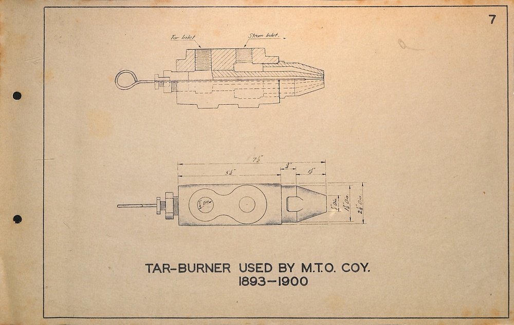
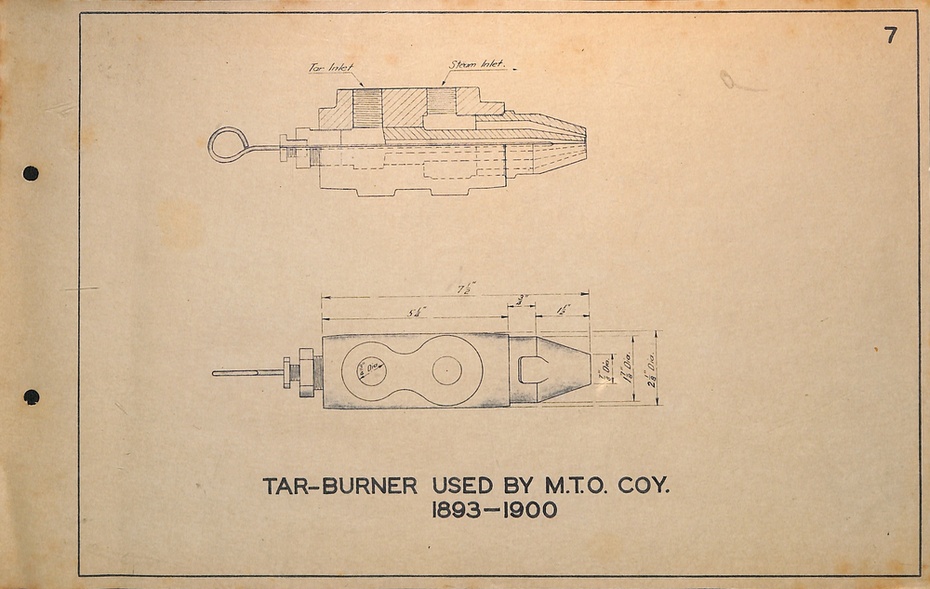
5 - Tar burner (see item 9696 for the actual item
6 - Yoke brackets for line drums
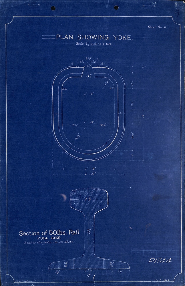
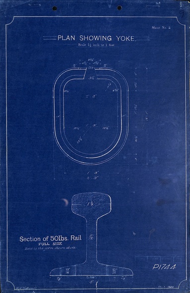
7 - Tunnel Yoke
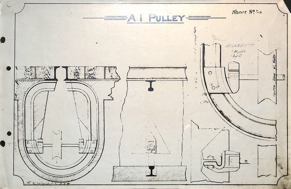
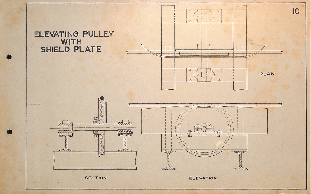
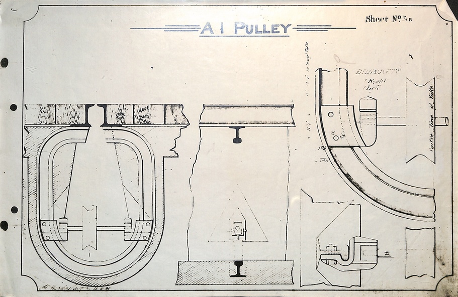
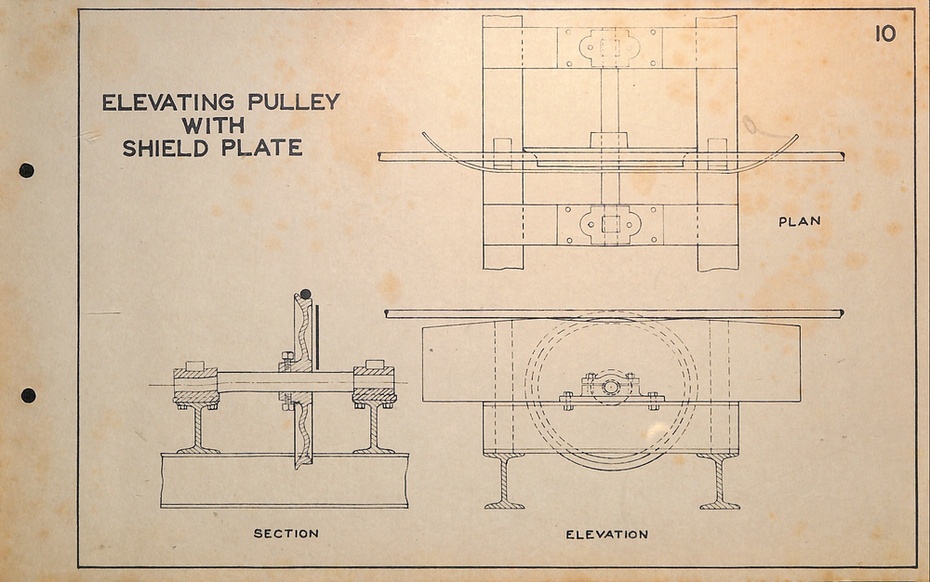
8 - Elevating wheel
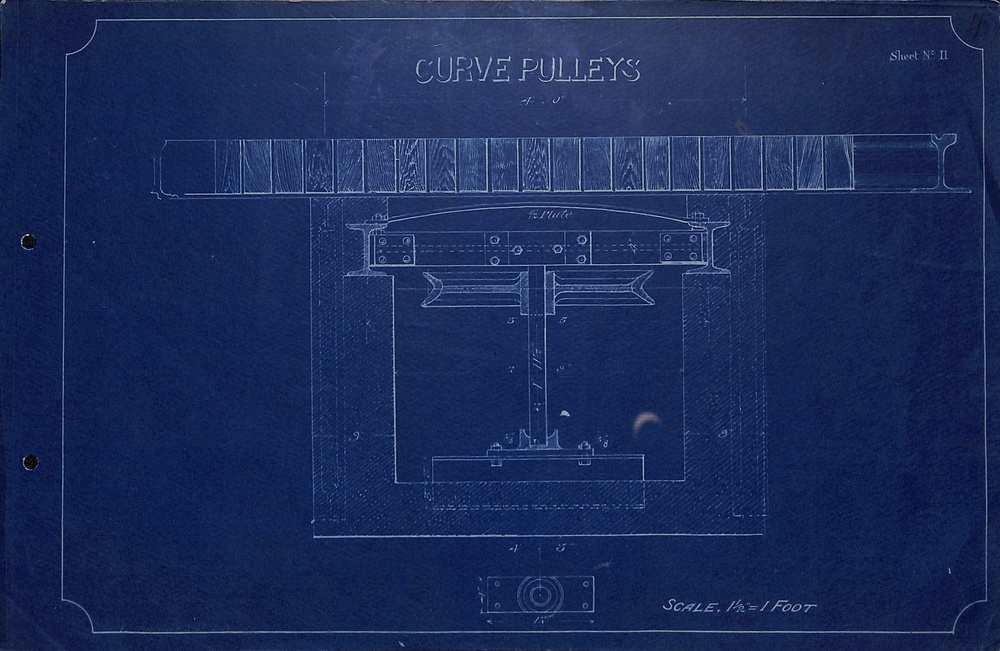
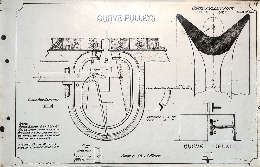
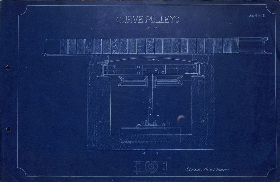
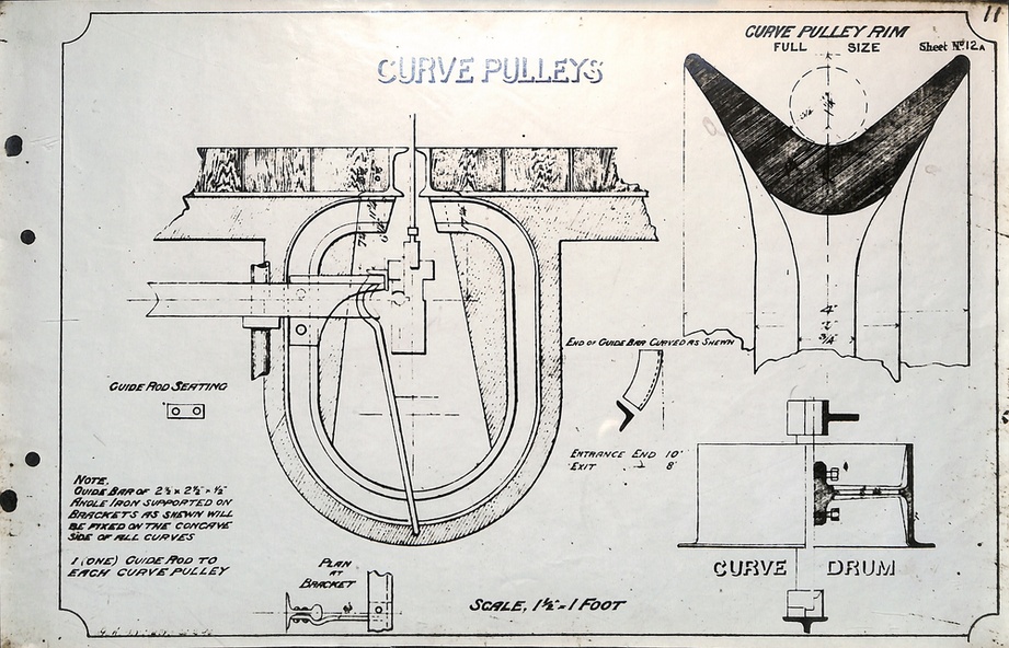
9 - Curve Pulley
10 - Curve Pulleys - different to above
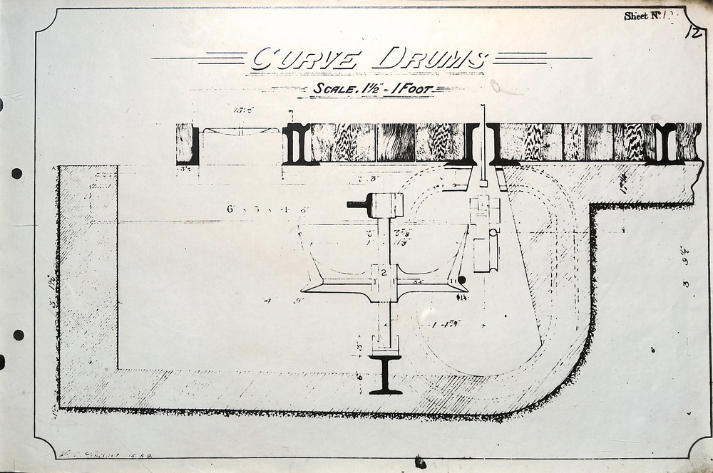
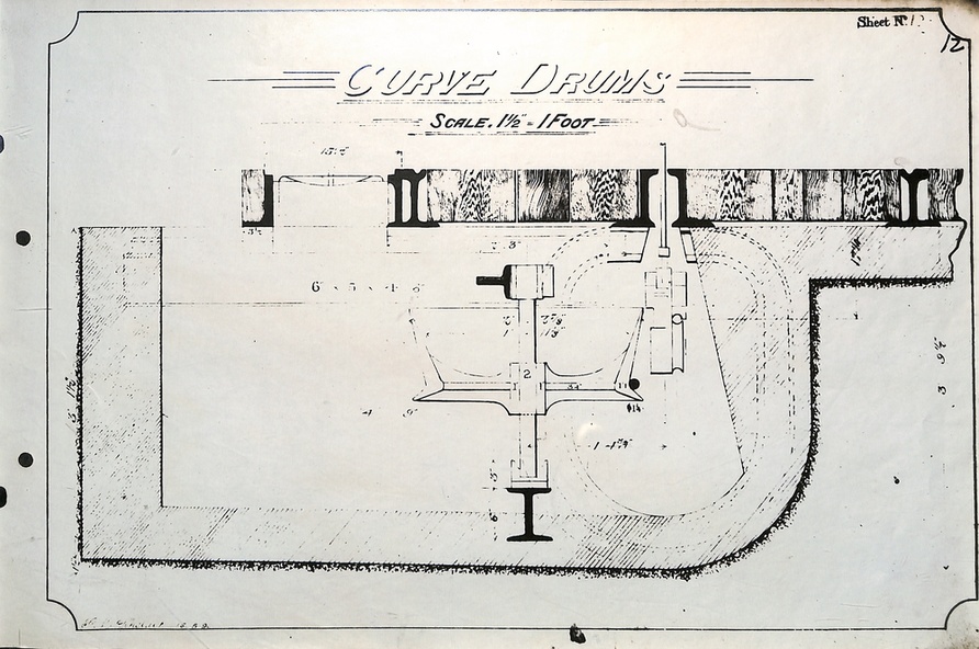
11 - Curve drums
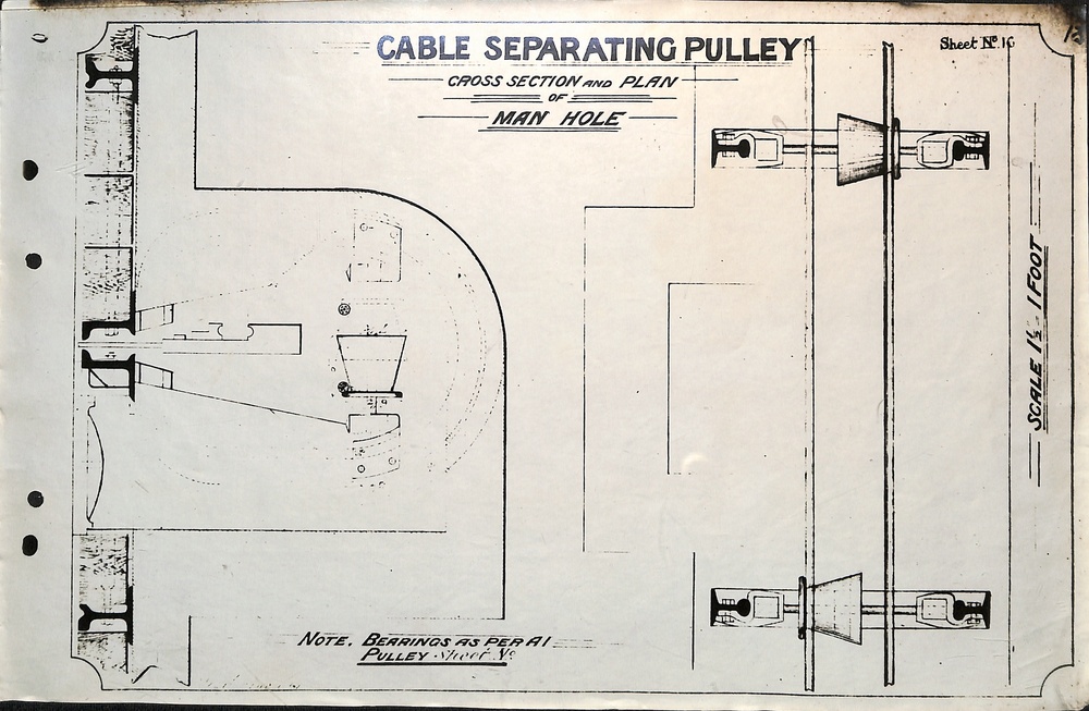
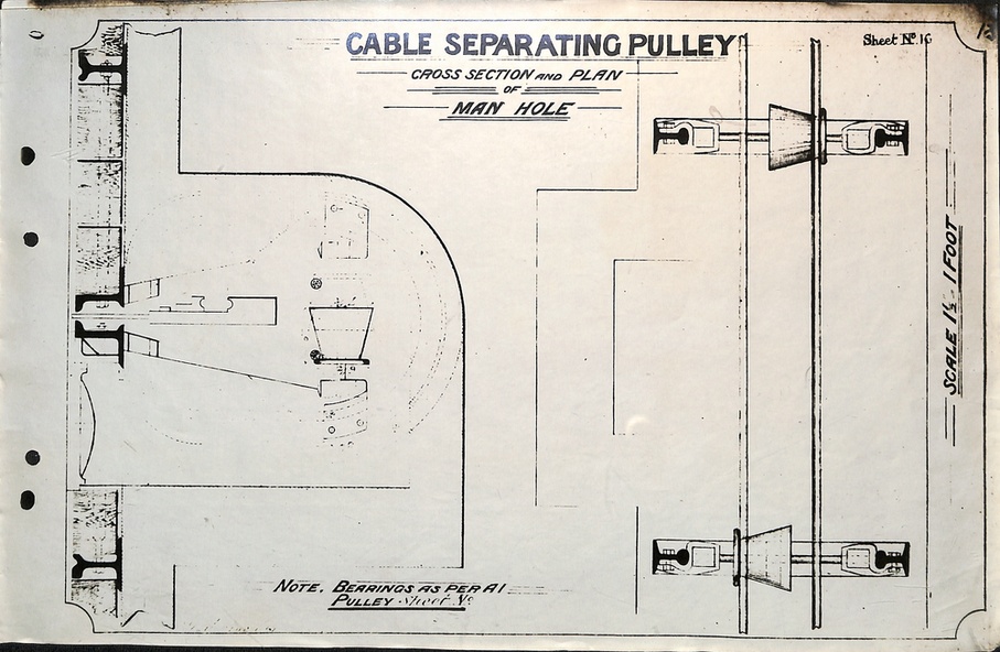
12 - cable separating pulley
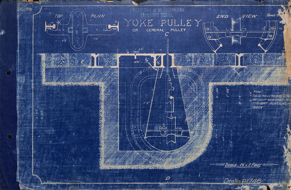
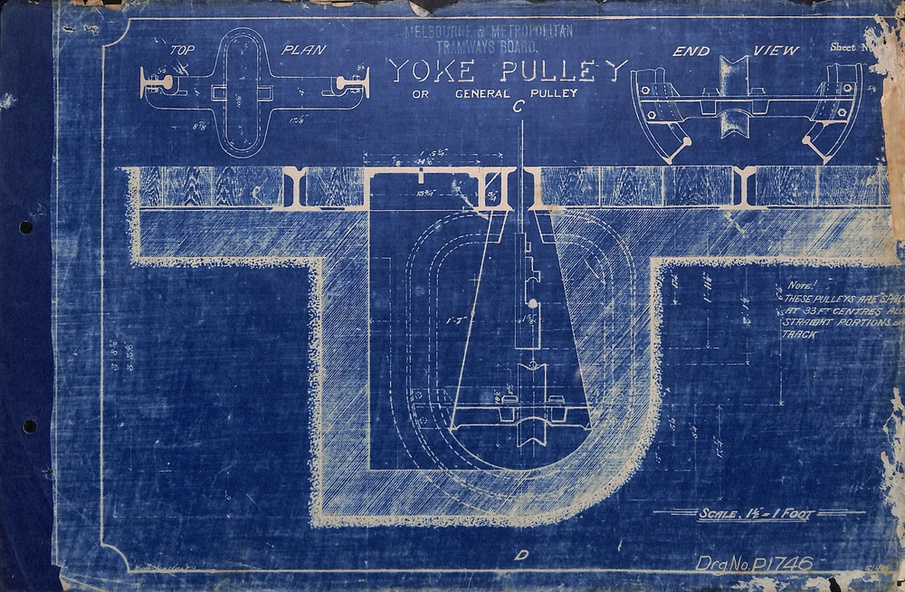
13 - Yoke Pulley
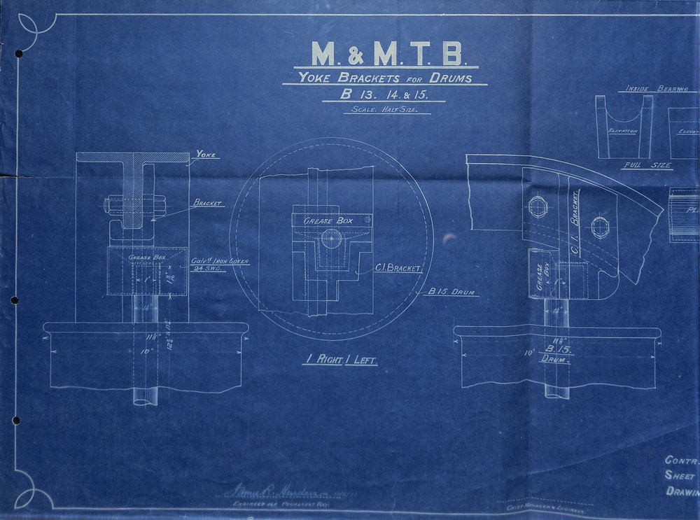
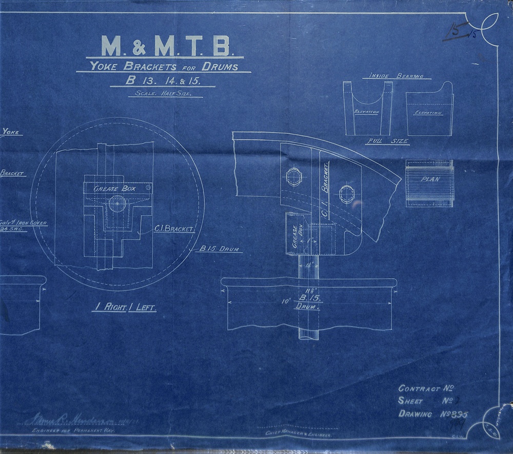
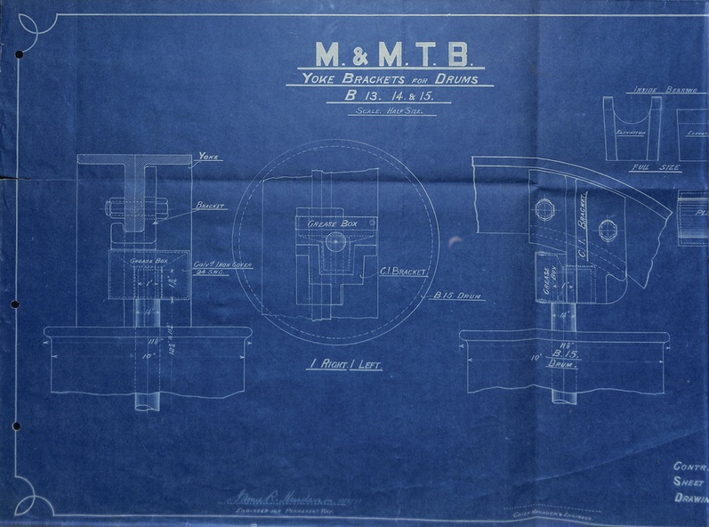
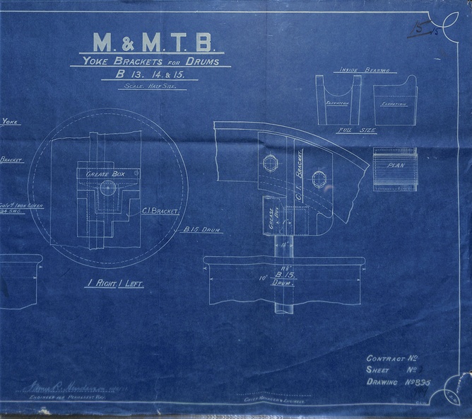
14 - Yoke brackets for drums (one sheet - two scans)
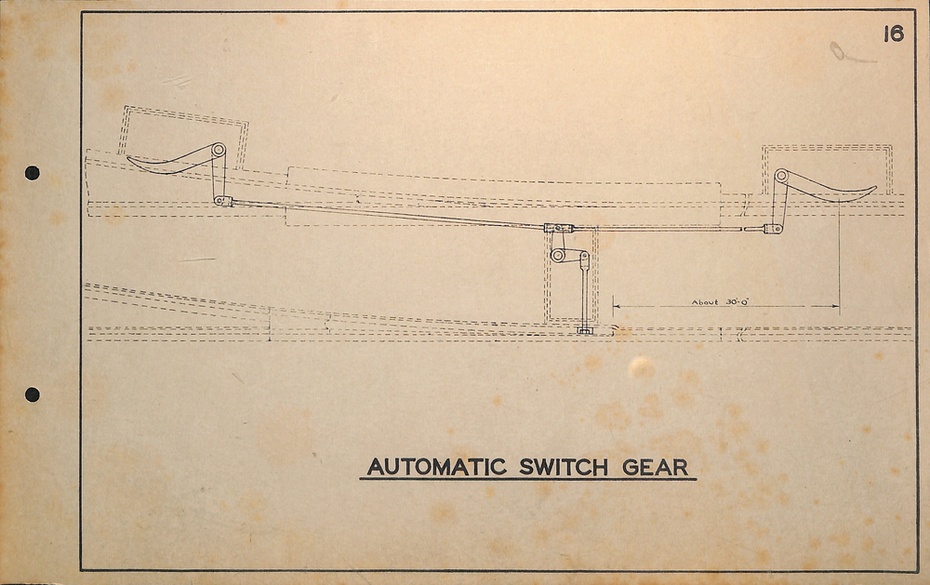
15 - Automatic Switch gear
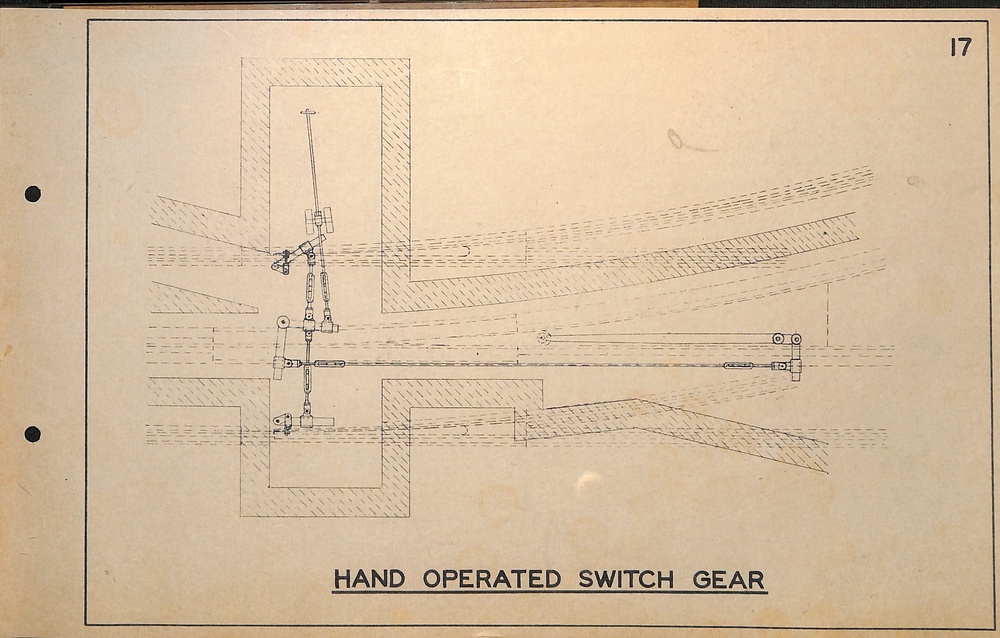
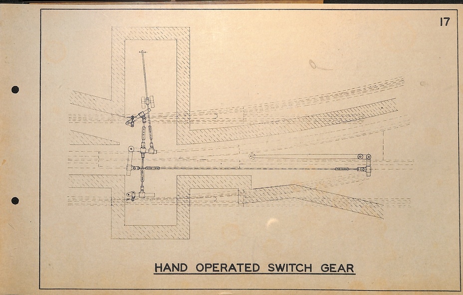
16 - Hand operated switch gear
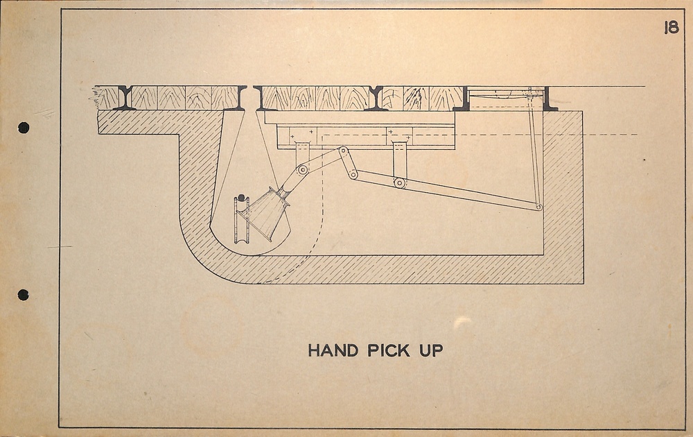
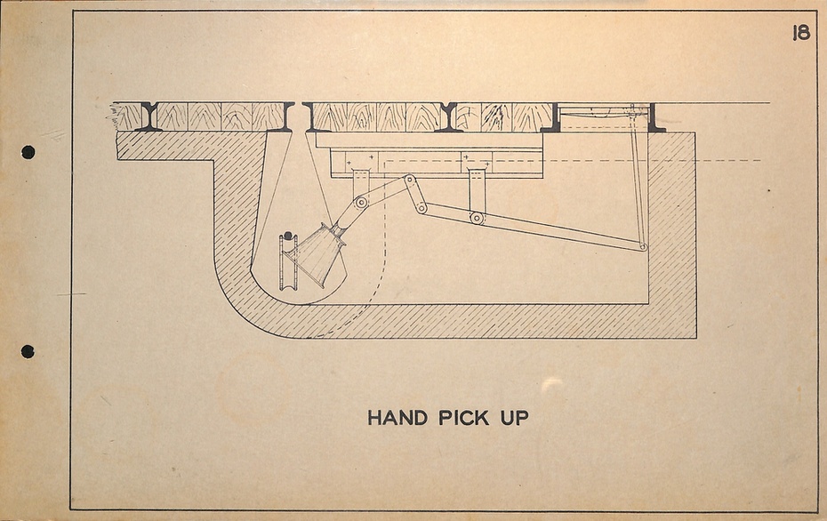
17 - Hand pickup
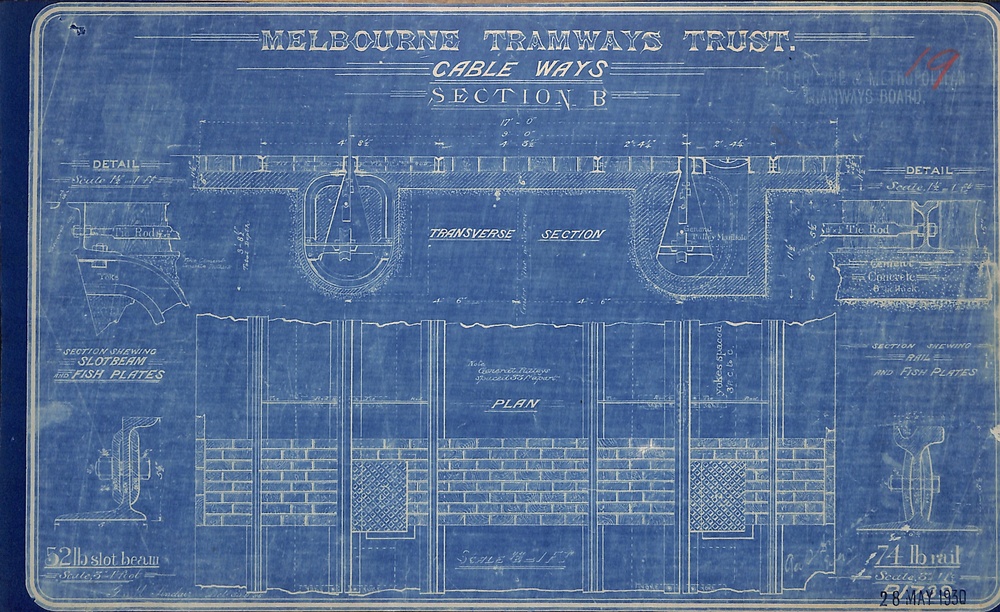
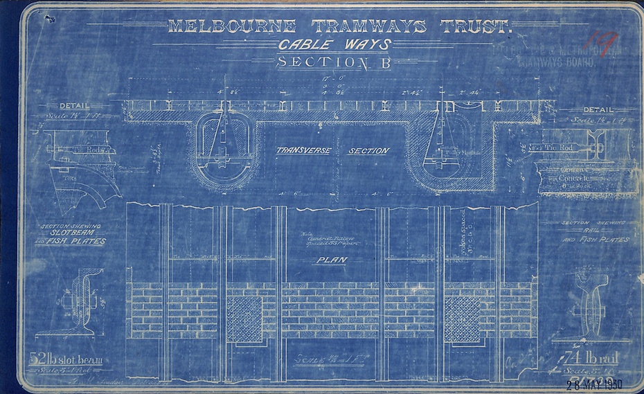
18 - cable ways - section B
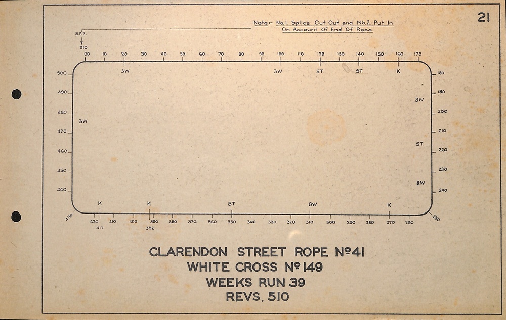
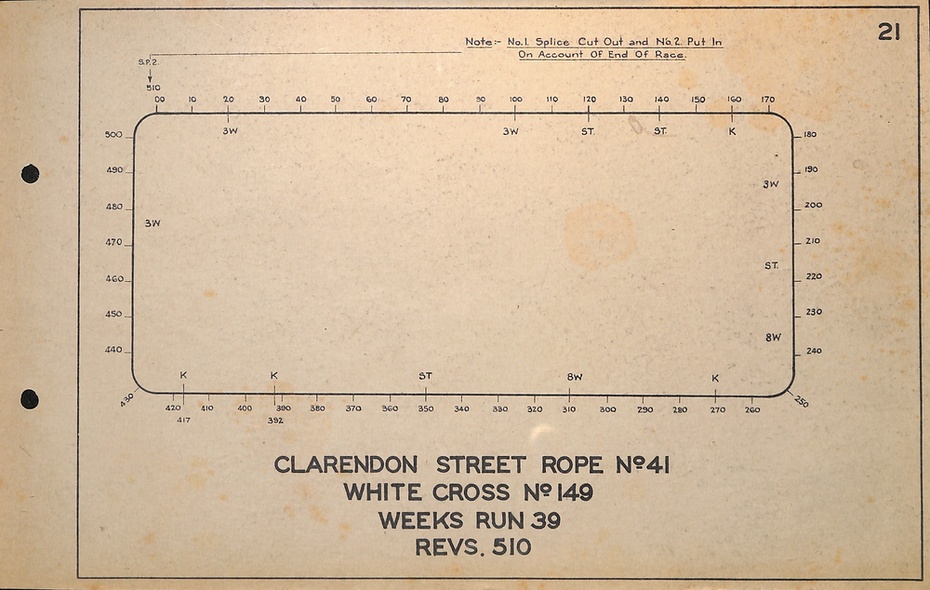
19 - Diagram of Rope - Clarendon St No. 41
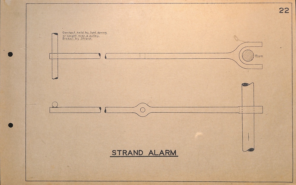
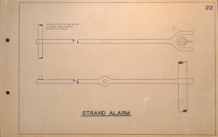
20 - Strand Alarm
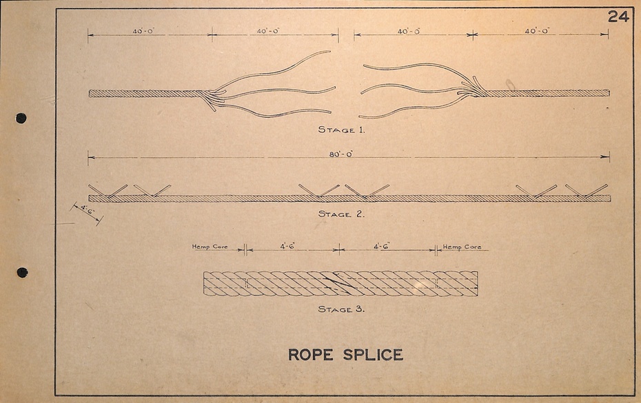
21 - Rope Splice
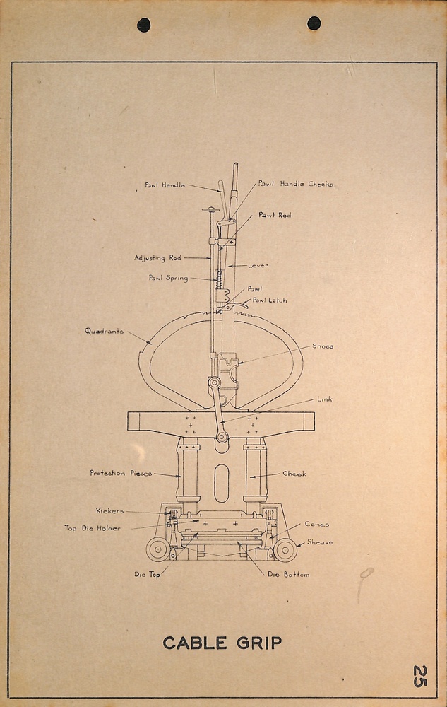
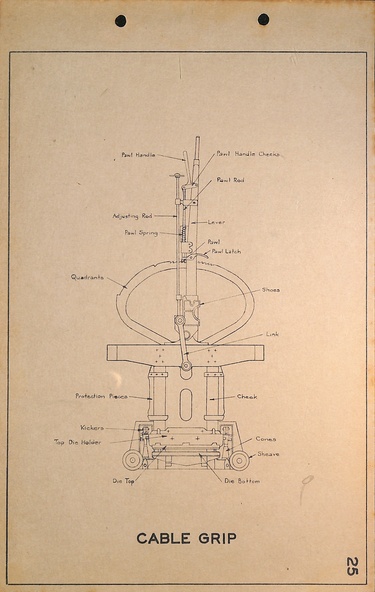
22 - Cable Grip
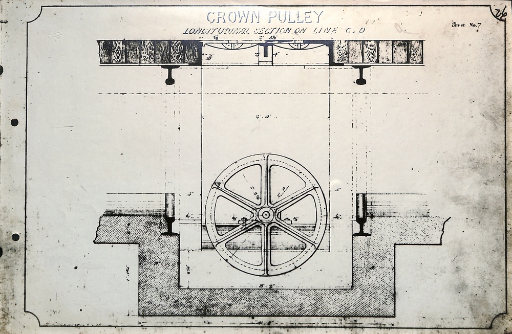
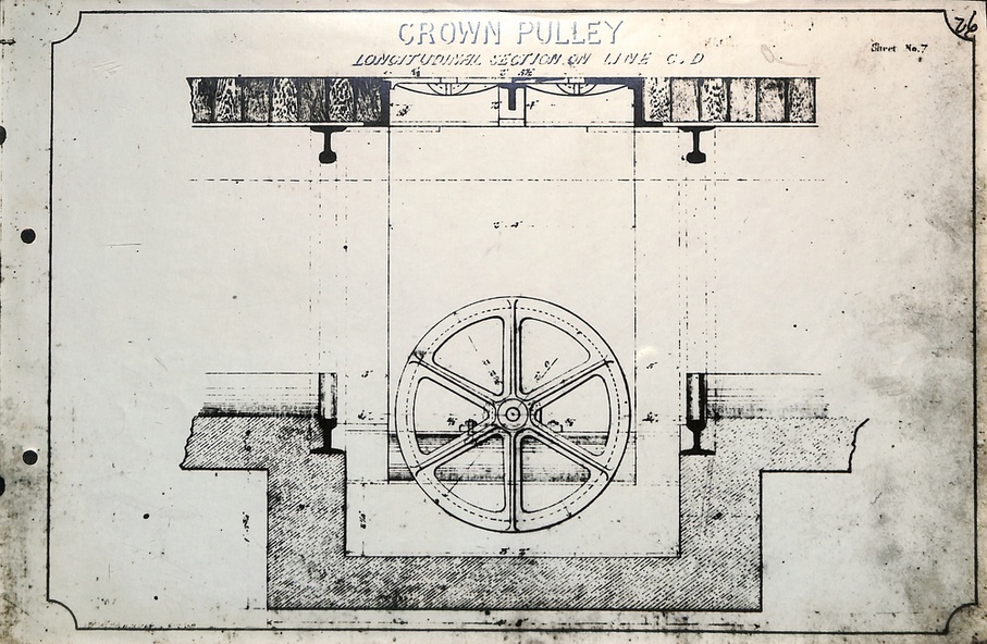
23 - Crown Pulley - Longitudinal section
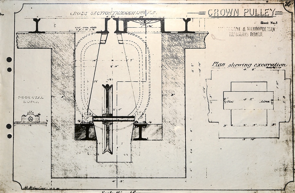
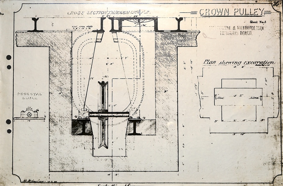
24 - Crown Pulley - cross section though line.
Significance
Yields information about the cable operations, drawings, pulleys, and how the various facilities or equipment was provided for.
Physical description
Set of 24 drawings that were used as an appendices to W R Pollocks Report "The Melbourne Cable Tramway System"