Showing 62 items
matching control valve
-
 Bay Steamers Maritime Museum
model steam engine
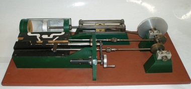
This model was found in the collection of Bay Steamers Maritime Museum. It is not knowt who created it but it is supposed that it was constructed to educate the many masters of the Wattle in the operation of a steam engine - a not so common mode of power these days. A Bay Steamers Maritime Museum examined the model in March 2012 and discovered that is was in poor repair. Using his existing knowledge, and with reference to some historic texts, he made some repairs and returned the model to working order. Here is his anaylsis of the situation as an excerpt from the Bay Steamers Maritime Museum newsletter Steamlines May 2012 "I was confronted with a model of a steam engine used years ago as a training aid for hopeful steam engineers. Already having a knowledge of steam operations, I considered a museum write-up for that model a ‘piece of cake’. However, on turning the model’s crankshaft, the valve timing seemed ‘out of kilter’ with the movement of the piston. Problem was that the two eccentrics on the crankshaft were not properly secured to it. Eventually I fastened the two eccentrics to the crankshaft where I felt that they should be and then realized that one of them had a chain-driven valve-timing device attached. This would be adjusted while an engine was running to achieve best performance and fuel economy whilst in operation by accurately controlling the period of time during which steam under pressure from the boiler would be admitted to the cylinder and give greater time for the steam to expand in the cylinder, move the piston and turn the crankshaft and thus, drive the attached apparatus. When the valves were correctly set up it was then possible to get the model to function properly.The model comprises a green section, which is the actual the model mounted on a brown painted board. There are two parts of the model, painted white representing the steam passages, and black representing the cast- iron portions of the cylinder-block casting, and of the main valve sliding between the cylinder a second sliding valve. Of the black portions, one slides back and forth being connected to a rod which is connected to an eccentric clamped to the crankshaft and is the nearer to the flywheel of two eccentrics. This eccentric is attached to the crankshaft at an angle of 90 degrees to the crank-pin attached to the flywheel. To operate the model simply turn the flywheel by means of the handle attached to its crank-pin. A second eccentric is also attached to the crankshaft, further away from the first eccentric, and it is adjusted to operate 90 degrees from the first eccentric (that is, 180 degrees from the crank-pin) A piston (painted silver) is located in a plastic cylinder and has a piston rod which passes through one end of the cylinder, (in actual practice a steam-proof gland seals the cylinder against loss of steam) terminating in a cross-head slide between four rails guiding it. From this cross-head, a connecting rod joins the piston-rod to the flywheel via the crank-pin attached to the flywheel which is part of the crankshaft. (In actual practice, a flywheel may not be used, particularly in a multi-cylinder engine.) The white portions of the model painted nearest to the cylinder represent the two steam ports cast into the main cylinder block, whilst one section painted in between those two represents the exhaust outlet (which may be connected to a condenser to conserve water, or to the open air). The main slide valve has three white-painted portions painted thereon. It has two white-painted marks representing the steam passages to the steam ports into the cylinder, and a third section in between the other two, being that part of the valve through which exhaust steam passes in line with the ports in the cylinder block. By rotating the flywheel, the operations of an engine will be observed as steam is admitted to the main valve via the gap between the two jaws of two moveable portions of a second sliding valve which is operated by the second eccentric attached to the crank-shaft. This eccentric is used to finely tune the valve timing of this model to obtain best running results of an engine. There are various methods used for reversing a steam engine. model compound steam engine, steam engine, model, crankshaft, valve, flywheel, wattle, engineer, eccentrics -
 Puffing Billy Railway
Lister Auto Truck
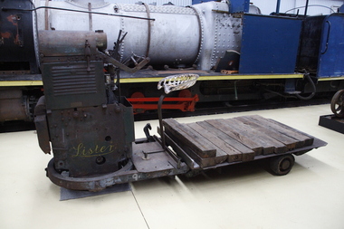
The Lister Auto-Truck was a small monowheel tractor built for moving light loads around factories, railway yards and similar sites. They were built by R A Lister and Company of Dursley, Gloucestershire, well known for their range of small stationary engines The Auto-Truck was one of several monowheel tractors to appear in the 1920s and '30s, with the availability of small, reliable petrol engines, as developed for motorcycles and the stationary engines for which Lister were already known. These were tricycle vehicles, with the single leading wheel used for both drive and steering. Their simple construction carried most of the mechanism on this wheel as a single unit, the chassis with the trailing wheels being little more than a trailer for balance. Simplicity was a key feature. The engines were single-cylinder and air-cooled. Ignition was by magneto, rather than requiring a battery and electrical system. One of these designs was produced in the 1920s by George Grist of the Auto Mower Co., Norton St Philip, Somerset. The engine was a JAP 600 cc four-stroke air-cooled sidevalve, a typical small engine of the time. The Auto Mower Co. were Lister agents and when Lister heard of this 'Auto-Truck' they bought one for use in their own factory. It was used to carry heavy engine castings from the foundry to the machine shop. Lister customers saw them and there was such interest in wanting to buy them that Lister negotiated with Auto Mower to build them under licence. Although Lister were already well known for their small petrol stationary engines, these were heavy cast-iron engines with water hopper cooling and unsuitable for vehicle use. Lister remained with the JAP engine for the Auto-Truck. The Auto-Truck was designed for use in factories or other places with smooth surfaces of concrete or tarmac. This allowed the use of small solid-tyred wheels with only simple suspension, making the vehicle simple, cheap and lightweight. They had little ability on soft surfaces though and could even topple over if driven carelessly across slopes. Their design was a compromise between the top-heavy nature of the tall engine grouping above its wheel and a well thought-out chassis for stability. The bearing between them was a large diameter ring roller bearing, mounted at the lowest part of the chassis. This gave rigidity and stability, even after long wear. A ring of rolled channel girder was attached to the engine group and rollers on the chassis carried the load upon this. On early Auto-Trucks this bearing is set very low, in line with the chassis members, and is covered by thin steel plates. The front panel of the engine cover is distinctive with large ventilation holes and a Lister signature cut through it. Strangely this panel is made of thick cast iron, providing substantial weight high on the engine and only adding to its top heaviness. To improve visibility of moving vehicles in noisy factories, this panel was often painted white, the rest of the vehicle being Lister's usual brunswick green. The driver was seated on a Brooks bicycle saddle, which in recognition of the lack of vehicle suspension, was carried on the end of a cantilevered bar that acted as a leaf spring. A wide handlebar on the engine group was used for steering. A squeeze bar the width of this handlebar engaged the clutch. Controls included a hand throttle, a gear lever with two forward and one reverse gears, and a large handbrake lever. The engine unit rotated freely for a full 360° rotation. When used in reverse, the Auto-Truck could either be driven from the saddle, looking backwards over the driver's shoulder; or they could dismount, swivel the engine unit around and control it as a pedestrian-controlled truck from behind. Under the engine cover were two equal diameter tanks, a fuel tank for petrol and a shorter oil tank. Engine and chain-drive lubrication used a total-loss oil system, controlled by a small pump and needle valve. Info Ref: Lister Auto-Truck - Wikipedia https://en.wikipedia.org/wiki/Lister_Auto-TruckHistoric - Industrial monowheel tractor for moving light loads around factories, railway yards and similar sites.The Lister Auto-Truck - small monowheel tractor Made of steel with three wheels. Powered by a J.A.P single cylinder petrol motor which is Hand Cranked to start.Lister puffing billy, lister, lister auto truck, monowheel tractor -
 Forests Commission Retired Personnel Association (FCRPA)
Driptorch - Firebug (hand held), c 1985
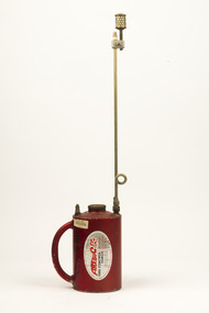
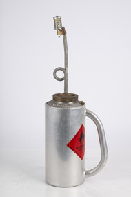
The origins of the humble handheld driptorch have been lost in time. They are widely used for ignition in controlled burning operations in forest and grasslands. The “Pacific Forester“ with its short central wand and somewhat leaky ball-valve was made by the American Wajax company in the 1940s. The Pacific Forester is slightly different in design from the more robust and common “Panama” driptorch first manufactured in 1933 and used extensively by Queensland cane farmers. The Panama is closely related to the current “Firebug” used in Victoria which is manufactured by Rodney Industries in Brisbane and has an offset wand design which gives it good balance. The fuel is a mixture of petrol and diesel and every FCV District had their own closely-guarded secret formula ... 2:1, 3:1, 1:1, 4:1 or 3:2 ratio. There was also the choice of 91, 95 or 98 octane petrol mixed with summer or winter diesel. Occasionally some of the old Avgas or Jet-A1 lying around the depot was added with a splash of engine oil to make the mixture stick to the fuel to be ignited. The fuel mixed also varied between autumn or spring, heathland, mixed forest, or high-intensity slash burnsCommon driptorch used throughout AustraliaDrip torch with handle Wand has loop and valve. The loop is designed to assist with even flow of fuel which flows out onto the burning head of the wand. Pressure equalising value in top of aluminum fuel container which holds 4 litres of burner mix. Gravitational feed of the driptorch allows the unit to drip fire, making it simple and quick to operate. Instructions for use. CF+L written with texta pen.bushfire -
 Ballarat Heritage Services
Tool - Object, Oriental Box Bellows
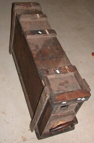
Japanese style box bellows (fukisashi/吹差鞴) reached their current and finalized form by about the sixth century. They are constructed almost entirely of wood and allow a smith to supply a highly controlled air blast to the forge by pulling and pushing the handle slowly back and forth. Using dual chambers and two sets of valves, the air is supplied on both the push and the pull stroke, and the blast may be highly intensified or stopped in an instant as needed by the smith.(http://islandblacksmith.ca/2015/06/why-you-need-a-swordsmiths-fuigo-box-bellows/, accessed 18 February 2018)Timber box with handle on the side which pulls out.fuigo bellows, japanese, bellows, fukisashi bellows, oriental box bellows, pump -
 Moorabbin Air Museum
Book (Item) - Operation And Service Instructions Types 569 To 574 Inclusive, De-Icer Distributing Valves And Type 576 And 577 4-Way Control Valves
... And 577 4-Way Control Valves Book Operation And Service ... -
Moorabbin Air Museum
Book (Item) - Overhaul Instructions De-Icer Distributing Valves Types 569, 570, 573,574 Four -Way Control Valves Types 567 And 577
... -Way Control Valves Types 567 And 577 Book Overhaul ...T.O. No. 03-1-6 Chapter 51 Part B -
Moorabbin Air Museum
Manual (Item) - Manuals for Valves - Cold air unit, Solenoid, Relief, Control;, Restrictor, Non-return, Vacuum, Duel Pressure
-
 Ballarat Tramway Museum
Slide - 27 mm sq slide/s - set of 3, Lilian Butler, views of the controls of a tram, c1971
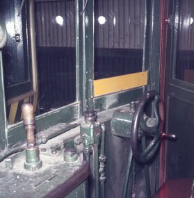
Yields information about the driver's cabin of various Ballarat trams.Set of three colour slides - AGFA blue and white plastic mount and two Kodachrome white cardboard slides of views of the controls of a tram. .1 - single truck tram, with a rotary brake valve, handbrake and controller .2 - photo with B23D controller. .3 - single truck tram with handbrake, rotary brake valve and Pay as you Enter sign. Photo from the collection of Lilian Butler. ballarat, tramways, trams, controllers, brake valves, handbrakes, signs -
 Ballarat Tramway Museum
Book, Westinghouse Brake Company of Australasia Ltd and George St. Concord West NSW, "Westinghouse Brake Repairs Parts", May. 1927
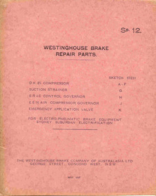
Thirteen sheet book, each sheet printed single side, secured with two metal clips and washers in a pink cover card cover, titled "Westinghouse brake repairs parts". Published May 1927, by Westinghouse Brake Co. of Australasia. Binders - "The Grip Binder" - nickel plated steel using sheets printed by The Westinghouse Brake & Saxby Signal Co. Ltd. Cover larger than the sheets. Details parts list for: DH25 - Motor Driven Air Compressor for 1500V DC ER4C - Control Governor ES16 - Air compressor Governor Emergency Application Valve Used for electro-pneumatic brake equipment - Sydney Suburban electrification. Scanned to the COTMA Website 4-10-2015."Colin Rutledge" stamped on top of page 1.trams, tramways, westinghouse, compressors, governors, equipment -
 Ballarat Tramway Museum
Document - Technical pamphlet/s, Westinghouse Brake Company of Australasia Limited and The Westinghouse Brake & Saxby Signal Co. Ltd. of 82 York Road and Kings Cross London, "The Westinghouse Brake with Electro-Pneumatic Control", Dec. 1926
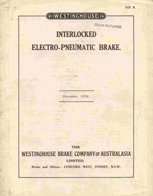
2285.1 - 12 page technical pamphlet (2 sheets of paper - pages 5 -10 formed as a concertina folded centre sheet) titled "Interlocked electo-pneumatic brake", published by Westinghouse Brake Company of Australasia Limited, December 1926. Manual D.P. 9. Stapled with two steel staples along fold. Describes in detail the electro-pneumatic brake system as used on Sydney Suburban trains, complete with diagrams, brake valve operation, magnet valve and isolating cock switch. 2285.2 - Six page technical pamphlet, titled "The Westinghouse Brake with electro-pneumatic control", published by Westinghouse Brake and Saxby Signal Co. 1915. Pages 3 and 4 have been tipped in the cover sheet. Describes standard brake equipment for use with electric trains and electro pneumatic control over the brakes. Gives details of house the brake valve (No. 18 EP) operates. Scanned to the COTMA Website 4-10-2015."Colin Rutledge" stamped on top of page 1.trams, tramways, westinghouse, electric trains, electro - pneumatic brakes, sydney suburban trains -
Moorabbin Air Museum
Manual (Item) - RAAF manuals on - non-return valves, valve box, cap assembly, mixer valve, springed rod, manual control unit, pressure switch, cold air unit
... assembly, mixer valve, springed rod, manual control unit, pressure... assembly, mixer valve, springed rod, manual control unit, pressure..., cap assembly, mixer valve, springed rod, manual control unit ... -
 Otway Districts Historical Society
Photograph, R. Preston, Down goods hauled by G42 about to depart Gellibrand, 14 December 1955
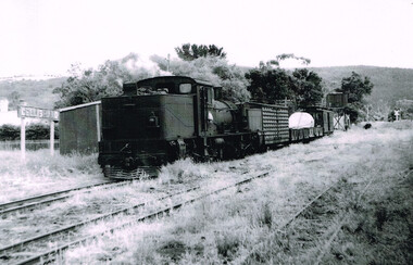
Drivers were highly skilled enginemen. Taking a train from Beech Forest to down to Gellibrand required the train to be controlled at 10 mph (16 km) without running out of air. When a brake application was made the brakes on the locomotive were applied harder than the train brakes. The brakes locked up and the engine would just slide along. Drivers used a retention valve on the loco, then released the loco brakes so as not to wear out the brake shoes. So the train pulled into Gellibrand ready to pull out again after refilling the loco with water.At Gellibrand, a Down goods train is about to depart the station on 14 December 1955. The train consists of the locomotive G42, a louvre van NO, two NQ wagons and a guard's or brake van NC. B/W.gellibrand; colac; beech forest; railway; -
 Queenscliffe Maritime Museum
Equipment - Sun valve
... back on. A sun valve is a flow control activated by sunlight.... It was never turned back on. A sun valve is a flow control activated ...The light was powered by a kerosene lantern that had to be kept alight by the keepers until the introduction of bottled acetylene gas in 1925. The light operated for 111 years until 1985 when it was turned off for a trial period. It was never turned back on. A sun valve is a flow control activated by sunlight heat which automatically shuts off gas during daylight hours. Relic from the Hovell light run on acetylene from 1925 to 1985Sun valve from the Hovell Pile Lighthovell pile light, south channel, port phillip -
 Box Hill RSL Inc.
Memorabilia - Walkie Talkie- USA, Galvin Manufacturing Co, c. 1942
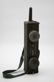
From the Imperial War Museums website (IWM UK): Second World War period transceiver set widely used by US, and Allied, Armed Forces in Italy, N W Europe, and the Pacific. The US Signal Corps developed the SCR-536 early in the Second World War, It was produced from 1942 onwards by the Galvin Manufacturing Co. By 1945 130,000 had been produced. The SCR-536 was an extremely popular set and was colloquially known as a "Handie-Talkie". It consisted of a five-valve, low-power, battery operated, AM (HF) transceiver that was designed for portability and ease of operation. It featured a single channel crystal control between 3.5 and 6Mc/s, and it had an R/T communication range of 1 mile over land and 3 miles over salt water. The set was switched into a receiving mode by extending the telescopic aerial, and to transmit the press-to-talk switch was depressed. The aerial was protected by a connected cover. The set was well-engineered and designed and could be held in one hand, hence "Handie-Talkie" . It was used virtually everywhere in the world, weighed only 2kg, and was proofed against fungi and moisture.The SCR-536 was also modified for use in military gliders under the designation SCR-585.Short range portable transceiver. A large green-painted metal box with perforated small round holes in the shape of hexagons (original perforated round black earpiece and mouthpiece missing). On the back is a long green webbing carrying strap. (not original)Between the earpiece and mouthpiece is a plaque that reads "SIGNAL CORPS US ARMY RADIO RECEIVER AND TRANSMITTER BC-611-C. SERIAL NUMBER: 3017. ORDER NUMBER: 1345-WF-43. MADE BY GALVIN MFG CORPORATION CHICAGO ILLINOIS. On label : FREQUENCY 3996 Kev/ CHANNEL/ BAT. DATE Red square stamp walkie talkie, handie talkie, telecommunication, ww2, world war 2, american, wireless equipment, signal corps, us army, transceiver, bc 611 c -
 Department of Energy, Environment and Climate Action
Pacific firelighter
The origins of the humble handheld driptorch have been lost in time. They are widely used for ignition in controlled burning operations in forest and grasslands. The “Pacific Forester“ with its short central wand and somewhat leaky ball-valve was made by the American Wajax company in the 1940s. The Pacific Forester is slightly different in design from the more robust and common “Panama” driptorch first manufactured in 1933 and used extensively by Queensland cane farmers. The Panama is closely related to the current “Firebug” used in Victoria which is manufactured by Rodney Industries in Brisbane and has an offset wand design which gives it good balance. The fuel is a mixture of petrol and diesel and every FCV District had their own closely-guarded secret formula ... 2:1, 3:1, 1:1, 4:1 or 3:2 ratio. There was also the choice of 91, 95 or 98 octane petrol mixed with summer or winter diesel. Occasionally some of the old Avgas or Jet-A1 lying around the depot was added with a splash of engine oil to make the mixture stick to the fuel to be ignited. The fuel mixed also varied between autumn or spring, heathland, mixed forest, or high-intensity slash burnsKerosene drip torch Short wand no valveBCR Holdingsforests commission victoria (fcv), planned burning, bushfire -
 Moorabbin Air Museum
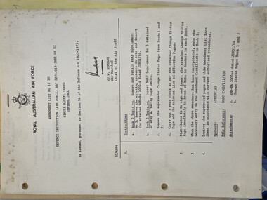
Manual (Item) - (SP) AAP 7276.019-3MB1 to B2 Single Barrel Servo Control Jack Amendment List 12
Released around 1970 by the Royal Australian Air Force. A manual for part model or type no B99-26-203 and B99-26-204 valve, fuel cut out type 16.royal australian air force, valve and fuel cut out type 16, australian air publication -
 Moorabbin Air Museum
Manual (Item) - (SP) AAP 7276.019-3 Single Barrel Servo Control Jack Type 103-35-1 Amendment List 6
Released around 1970 by the Royal Australian Air Force. A manual for part model or type no B99-26-203 and B99-26-204 valve, fuel cut out type 16.royal australian air force, valve and fuel cut out type 16, australian air publication -
 Trafalgar Holden Museum
Vehicle - VZ Holden Executive, 2004
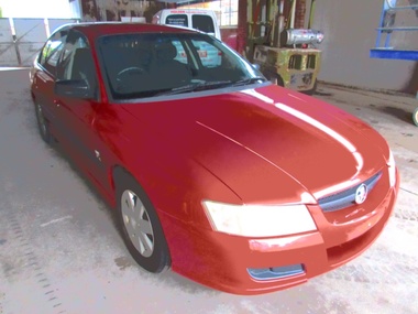
Released in August 2004, the VZ series was a minor facelift of the previous VY series that featured a new V6 engine in different tune guises. The powerplants included 175 and 190 kW (235 and 255 hp), 3.6-litre Alloytec V6 engines in place of the older 3.8-litre Ecotec V6. Other changes to the V6 was the loss of the supercharger that was included in the S models The VZ Commodore was available in several model variations, most of which carried over from the VY range, with the exception of the newly introduced SV6, a specification level that replaced the S range. All models in the Commodore range (Executive, Acclaim, Berlina, Calais, SV6, SV8 and SS) were available as sedans. The advanced 3.6-litre Alloytec engines were more powerful, responsive and fuel-efficient than the outgoing Ecotec V6. To achieve 190 kW (255 hp), the Alloytec V6 gains variable valve timing on both inlet and exhaust sides as well as a dual stage intake manifold, while the 175 kW (235 hp) version retains variable valve timing on the inlet side only. Sales of the VZ series failed to match those of the preceding VY in light of rising small car sales, higher fuel prices and growing interest in the whole new replacement, the VE series. Selected models bring advanced active safety features that electronically assist the driver to maintain vehicle control in emergency situations. VZ Holden 4 door sedan with red body paint and fabric upholsteryLion badge front grille,V6 badge on mudguards. Executive badge on RHS of boot and Comnmodore on LHS. Lion badge on middle of bootvehicle, vz holden, car -
 Linton and District Historical Society Inc
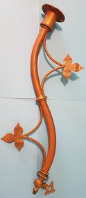
Gas light bracket, Gas Light, Presbyterian Church, Linton
... a valve, presumably to control the flow of gas. Beyond this valve..., presumably to control the flow of gas. Beyond this valve, the end ...Until Linton was connected to the statewide electricity grid in 1939, this gas light was used to light the altar at the Presbyterian Church in Linton.Curved gas light wall bracket, ornamented with leaves. One end designed to be attached to a wall, the other end has a valve, presumably to control the flow of gas. Beyond this valve, the end of the fitting is threaded, to facilitate attachment of a glass cover.gas lighting, presbyterian church linton -
Moorabbin Air Museum
Document (Item) - (SP) Technical Orders - multitude - list in "Context"
Possibly related to navigationtechnical order an 03-10abb-163 cyl plug selector valve assy overhaul with parts breakdown, technical order an 03-5-308 switch pressure actuated overhaul with parts breakdown, technical order an 05-55a-13 d-c selsyn position indicators and transmitters, technical order an-03-10abb-237 swing check valve overhaul with parts breakdown, technical order to-00-20a-2 airplane maintenance forms, technical order to-01-1-390 food and galley equipment responsibility, technical order to-01-1-515 rework solenoid control head part 966129, technical order to-01-1-619 oxygen regulators inspection and replacement, technical order to-02-10ab-1 r985 aircraft engines operations, technical order to-03-1-6 solenoid meshing devices ops service overhaul, technical order to-06-1-8 fuels and lubricants, technical order to-06-10-1 lubrication oils grades and use, technical order to-08-5-10 radio scr-578-a defective reels rl-48, technical order to-1-1-383 removal of ammunition from aircraft, technical order to-10-25-3 film developer assy operations servicing parts catalog, technical order to-14s3-1-503 inspection of life raft co2 cylinders, technical order to-15a1-2-12-3 air pressure regulator overhaul, technical order to-15h4-2-2-3 ignition units overhaul, technical order to-15h6-2-2-123 cockpit temperature control box, technical order to-15h6-2-2-13 cockpit temperature control box, technical order to-15h6-2-2-163 cockpit temperature control box overhaul, technical order to-1f-1-525 safety wirting pilot oxygen shutoff valve, technical order to-1f-86-210 sabre electrical connector for test equipment, technical order to-2r-0470-12 an 02a-40eb-2 aircraft engines service, technical order to-2r-0470-13 an 02a-40eb-3 aircraft engines overhaul, technical order to-2r-0470-14 an 02a-40eb-4 aircraft engines parts breakdown, technical order to-4s-1-2 high pressure air valve cores, technical order to-4s5-2-3 tail skid shock struts overhaul, technical order to-5f4-3-3 true airspeed signal control amplifier overhaul, technical order to-6j13-2-1-501 dual float switch assy installation, technical order to-6j14-1-5 torque values self sealing bladder cell multi bolt fittings, technical order to-6j3-4-15-4a vs-2 fuel regulator parts breakdown, technical order to-6j5-15-3 fuel filetr assy overhaul, technical order to-6j5-15-4 fuel filter assy parts breakdown, technical order to-6j5-18-3 micronic filters overhaul, technical order to-6j5-18-4 micronic filters parts breakdown, technical order to-6j5-24-3 av fuel filter replaceable micronic element, technical order to-6j5-5-3 fuel filter 03s12166d overhaul with parts breakdown, technical order to-6r-1-2 engine carburetor installation, technical order to-6r1-3-1-35 bendix injector carburetor overhaul, technical order to-6r9-2-11-3 valve check overhaul with parts breakdown, technical order to-6r9-2-12-3 swing check valve overhaul with parts breakdown, technical order to-6r9-2-14-3 check valve flow indicator overhaul wth parts breakdown, technical order to-8a6-3-3-3 ac generator overhaul, technical order to-8a6-8-4-4 engine driven aircraft generator parts breakdown, technical order to-8a6-9-3-3 aircraft ac generator overhaul, technical order to-8d1-21-3-33 fractional horsepower motor 5ba25aj28b overhaul with parts breakdown, technical order to-8d1-21-3-33 fractional horsepower motor 5ba25mj426b overhaul with parts breakdown, technical order to-8d1-29-2-3 direct current motor parts breakdown, technical order to-8d1-9-13-23 oil cooler flap control overhaul parts breakdown, technical order to-8d1-9-19-3 direct current motor overhaul with parts breakdown, technical order to-8d1-9-21-3 electromechanical linear actuator overhaul, technical order to-8d1-9-21-4 electromechanical linear actuator parts breakdown, technical order to-8d1-9-22-3 electromechanical power unit overhaul, technical order to-8d1-9-22-4 electromechanical power unit parts breakdown, technical order to-8d3-8-6-3 position light flasher overhaul, technical order to-8d6-5-4-504 mod westinghouse generator a45j247, technical order to-8e2-5-2-13 aircraft magnetos overhaul, technical order to-8e2-5-2-14 aircraft magnetos parts breakdown, technical order to-8ri-3-5-3 generator field control relay m-2 overhaul, technical order to-9h4-2-24-4a stratopower hydraulic pump parts breakdown -
 Forests Commission Retired Personnel Association (FCRPA)
Driptorch - hand held - unknown date, design or manufacturer
The origins of the humble handheld driptorch have been lost in time. They are widely used for ignition in controlled burning operations in forest and grasslands. The date, origins and manufacturer of this particular model are unknown. The “Pacific Forester“ with its short central wand and somewhat leaky ball-valve was made by the American Wajax company in the 1940s. The Pacific Forester is slightly different in design from the more robust and common “Panama” driptorch first manufactured in 1933 and used extensively by Queensland cane farmers. The Panama is closely related to the current “Firebug” used in Victoria which is manufactured by Rodney Industries in Brisbane. The fuel is a mixture of petrol and diesel and every FCV District had their own closely-guarded secret formula ... 2:1, 3:1, 1:1, 4:1 or 3:2 ratio. There was also the choice of 91, 95 or 98 octane petrol mixed with summer or winter diesel. Occasionally some of the old Avgas or Jet-A1 lying around the depot was added with a splash of engine oil to make the mixture stick to the fuel to be ignited. The fuel mixed also varied between autumn or spring, heathland, mixed forest, or high-intensity slash burnsEarly driptorch designDrip torch with handle Wand has loop and valve. The loop is designed to assist with even flow of fuel which flows out onto the burning head of the wand. Soldered tin fuel container which holds burner mix. Gravitational feed of the driptorch allows the unit to drip fire, making it simple and quick to operate. bushfire, forests commission victoria (fcv) -
 Melbourne Tram Museum
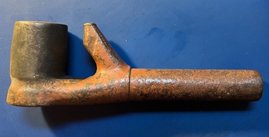
Functional object - brake handle, Melbourne & Metropolitan Tramways Board (MMTB)
Used by drivers to control the brakes on an air-braked tram. Designed to fit a Westinghouse self lapping W type brake valve.An essential part for the control of an air-braked tramcar.Brake handle or key consisting of cast steel handle and a welded section that fits into the brake valve. The angled section allows the handle to be removed when the brake is fully applied.tramcars, trams, brakes, westinghouse, drivers -
 Forests Commission Retired Personnel Association (FCRPA)
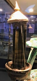
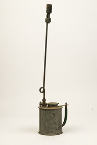
Burning wand - kerosene, c 1950
The origins of the humble handheld driptorch have been lost in time. They are widely used for ignition in controlled burning operations in forest and grasslands. This "home made" burner wand uses kerosene and dates from the 1950s. It has an unusual long handle with a bend and wick one one end.Unusual "home made" design Long handle burning wand with a wick at one end. Brass flow valve in the middle. Base attached to a container of kerosene and has a screw cap. bushfire, forests commission victoria (fcv) -
 Melbourne Tram Museum
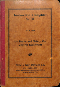
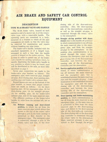
Document - Instruction, Safety Car Devices Co. St Louis, "Instruction Pamphlet S-100, Air Brake and Safety Car Control Equipment", Jul. 1924
Instruction - 108 pages + 9 fold out drawings glued and stapled in at the rear + card covers with red cloth binding, rounded right hand edges, centre stapled. Titled "Instruction Pamphlet S-100, Air Brake and Safety Car Control Equipment", published July 1924 by the Safety Car Devices Co. St Louis. Includes the M28 Brake valve. Describes in detail the rules for operation, parts, description, M28 Brake Valves, Maintenance, Practical car tests, hints, defects. The 9 drawings at the rear of the document give detail arrangements of the piping and control equipment. Book scanned into three sections. See also Reg Item 3513 for another similar document.on top of first page "C. Hodgson"trams, tramways, electrical engineering, electrical equipment, air compressors, brakes, instructions, maintenance, controllers -
 Melbourne Tram Museum
Document - Instruction, "Air Brake Safety Car Control Equipment", 1920's
Instruction - 24 pages, with two punch holes and stapled on the left hand side titled "Air Brake Safety Car Control Equipment" number 84450.1B, pages 3 to 26. Details the M28 brake valve, sanding features, operation, door and step controllers, check valve, CP-25C air compressor, brake valves, air compressor governors, drawings of piping, maintenance, testing, faults and general operation. See Reg Item. 3478 for another similar document. No details as to who published it or dates.trams, tramways, electrical engineering, electrical equipment, air compressors, brakes, instructions, maintenance, controllers -
 Melbourne Tram Museum
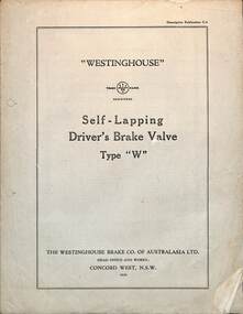
Document, The Westinghouse Brake Co AAsia Ltd, "Westinghouse self-lapping driver's brake valve Type W", 1936
"Westinghouse Australia self-lapping driver's brake valve Type W" circular No. C6 dated 1936, describing the type of brake valve, its features, operations, adjustment, associated double check valve and drawings shown with parts. This type of valve was used by the MMTB, replacing the Manual Lap type on almost the entire fleet. It gives a lot better control over the braking of a tram by drivers.Yields information about the Westinghouse Type W brake valve.Document or catalogue circular - 4 loose pages, quarto No. C6tramways, technical information, tramcars, brakes, brake valves, westinghouse -
 Melbourne Tram Museum
drawing - Folder with papers, Melbourne & Metropolitan Tramways Board (MMTB), "PCM Tram Equipment", 1970's?
Foolscap Manila Folder titled "PCM Tram Equipment" with the following papers secured with an Arnos binder. Many of the documents seem to have been copied onto heat sensitive paper. Have tissue paper separating them. 1. Wiring Diagram - GE PCM Control Equipment - R4284B. 2. Westinghouse - Load test on Repair Railway Motors 3. Letter to Chief Engineer MMTB from Australian General Electric - 23/7/1935 - re delivery of 15 cases of PCM Equipment by ship and attaching drawings. 4. Drawings and maintenance notes for above - includes field shunts, magnet valves, cases, 5. GE Specification Ry-5313 - General Electric PCM Control for 4-40HP 600Volt Motors with Shunted FieldsOn rear cover in ink "To Norm Cross"trams, tramways, electro pneumatic, pcm, controllers, general electric, mmtb, tramcars -
 Department of Energy, Environment and Climate Action
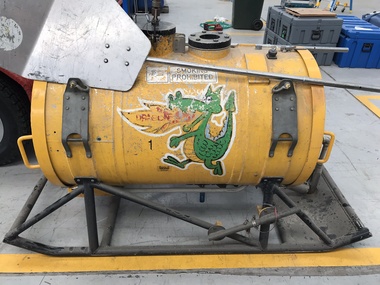
Aerial Drip Torch (ADT) or "Dragon"
The Aerial Drip Torch (ADT) was an idea conceived in Canada in the 1970s by John Muraro It was developed in 1982 by the New Zealand Forest Service to become the Ashley Aphid Helitorch. Forestry Tasmania acquired one of the machines and modified it in February 1987. Also known as a dragon helitorch it consisted of a large 135-litre tank containing jellied petrol, a displacement pump, propane ignition system, burner nozzle and fire extinguisher system. It was first trialled in Victoria at Swifts Creek in 1991 and the Aerial Drip Torch (ADT) has now become standard practice.Two Aerial Drip Torches (ADTs) were built in the 1990s by the Fire Equipment Development Centre at North Altona, They were developed in conjunction with the Department of Conservation and Land Management in Western Australia. The first was trialled during the 1991/92 autumn burning season. The machine proved to be successful and a second machine was introduced in 1998 to assist with burning operations across the State. The ADTs were commonly used for regeneration burning (controlled burning of logging slash). The first ADT introduced in 1992 had a dry weight of 160kg and a capacity of 130 litres, providing about an hour of operation. Following initial use, systematic modifications were adapted including improved ignition of gel at the drop tube, installation of an air bleed valve at the pump to assist pump priming and improved mounting brackets for the CO2 bottles and propane canister attached to the machine. The second, and lightweight ADT, introduced in 1998 had a dry weight of 68kg and a capacity of 200 litres due to a smaller lightweight frame and plastic (Polyfin) tank. In operation the ADT is suspended below a helicopter via four strops attached to the vessel and a cable to the helicopter cargo hook. Gelled fuel is dispensed via a drop tube which is attached to the pump outlet of the machine, and ignited via a gas torch. Safety features built into the first ADT were: a brass melting plug designed to be activated at 200 C bursting disc designed to burst at170 Kpa should the vessel over pressurise. a pressure relief valve set to 35 Kpa ( vessel operated between 16 &34 Kpa) a low pressure sensor designed to shut down the machine should the vessel pressure drop below 15Kpa. the vessel is filled with CO2 above the gelled fuel to eliminate ignition with in the vessel. CO2 is used to expel any residue of ignited gel from the drop tube to prevent ignition when flying outside the boundaries of the burning area. See FIRE EQUIPMENT NOTE - 46 [ https://drive.google.com/file/d/1CKtcH-3rUlrtbE9dkNP27PYT2-raVVhF/view ]forests commission victoria (fcv), bushfire, bushfire aviation, planned burning -
Moorabbin Air Museum
Manual - Flight simulators, Redifon Three Axis Motion System Operating and Maintenance Manual
... /power unit/servo jack Pressure control valves Speed control ...Overview of operation & maintenance of Redifon flight simulators, circa 1968Spiral bound manualnon-fictionOverview of operation & maintenance of Redifon flight simulators, circa 1968motion systems, hydraulic systems/pump/power unit/servo jack, pressure control valves, speed control valves, locking struts, pressure relief valves -
 Geoffrey Kaye Museum of Anaesthetic History
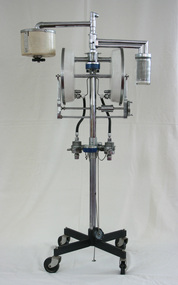
Machine - Portable dental and midwifery anaesthetic machine, Commonwealth Industrial Gases Ltd, circa 1950
This gas anaesthesia machine comprises a four yolk manifold, two circular metal components for nitrous oxide and two for oxygen. It is mounted atop a four pointed stand on casters for portability. In addition to reducing valves and regulators, the main stand also supports a cream-coloured, cylindrical Austox fractional rebreather and an ether vaporiser with variable bypass control within a circular glass container. portable, anaesthesia, midwifery, dentistry, obstetrics, oxygen, nitrous oxide, commonwealth industrial gases ltd, cig, austox fractional rebreather, ether vaporiser, variable bypass control, 1950