Showing 58 items
matching loading systems
-
 Ballarat Tramway Museum
Newspaper, The Courier Ballarat, "Story of Ballarat's Horse Trams", 19/06/1937 12:00:00 AM
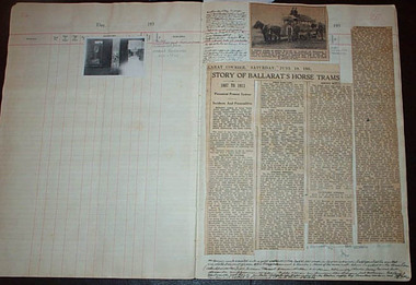
Newspaper clipping contained within Reg. Item 2488, page 25 and 27, from The Courier, Sat. 19 June 1937, titled "Story of Ballarat's Horse Trams", 1887 to 1913. Report of a paper presented to the Ballarat Historical Society by Inspector H. P. James the previous Tuesday night. Comprises four columns of text, pasted into the book titled "Of Other Days". General image of page 25 - see image btm2489i1.jpg. For page 27, see image btm2489i3.jpg - shows positioning of Reg. Items 2490, 91 and 92. Notes details of the genesis of the system, personalities involved with the construction, details of the works, depot, Duncan and Fraser car builders, early workers, formal opening, services, extension to Sebastopol, the horses, drivers, uniforms, (and on page 27) collection of fares, housing for the staff, horse feed (chart), passenger loads, conductors, rail and track cleaning and general operational notes. Has photo of a horse tram, with two drivers and conductors and handwritten note, remarking about the Conductor's "Receivers" in the photograph. See image btm2489i2.jpg Two hand written notes in ink, give details of Mr. Bob Haines and Matthew Buckley. Note Item Not formally Numbered.Numerous on page, mainly in ink.horse trams, sebastopol, crews, depot -
 Ballarat Tramway Museum
Manual, Bell Punch Co, "The Ultimate Fare Collection System", c1948
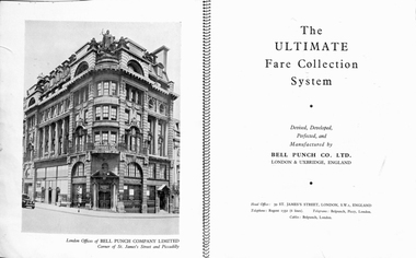
3628.1 - Book with orange covers, 22 pages on gloss paper, bound with fine wire binding titled "The Ultimate Fare Collection System", manufactured by the Bell Punch Co. of London England. Has a address details of the company, photo of the London Offices, photo of company factory in Uxbridge in 1946, details of the Ultimate machines, copies of sample tickets, general description, description, photographs, method of operation., machine loading, maintenance, ticket box and advantages of the system. 3628.2 - contained within .1, two copies of a two page pamphlet, reprinted from "Modern Transport", May 14, 1949 titled "New Fare Collection System / Ultimate in Production by Bell Punch". Gives details of the Ultimate machines. Have been stapled together. 3628.3 - contained within .1, Four page printed pamphlet titled "Wolverhampton Corporation Transport Department / The 'Ultimate' System", gives details and instructions regarding the machines and their use. Has initials "AHW / 500 / 25226" in the bottom right hand corner of 4th page.On 3628.1 in pencil "NC 23456 and NC24536"trams, tramways, tickets, ticket machines, buses -
 Ballarat Tramway Museum
Ephemera - Timetable/s, State Electricity Commission of Victoria (SECV), "Official Time Table Bendigo June 1940", Jun. 1940
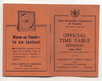
Centre pages show a map of the system and the sections. The extension to North Bendigo is yet to be constructed. Gives times for trams leaving the city or the terminals for the routes and for the Eaglehawk route, leaving Long Gully Bridge. Has four SECV Advertisements within the book for hot water, ovens - cookers, toasters and electric fan heaters. Three copies held. See item 5356 for a digital image of the same document with a photograph of Len Smith of Geelong loading a pram into a Birney tram.Provides details of 1940 tram services in Bendigo.Forty-page booklet, with orange lightweight covers, saddle-stapled, SECV Provincial Tramways with the title "Official Time Table Bendigo June 1940". Has address if Hargreaves St Bendigo on bottom of the cover. Two copies held.bendigo, timetables, secv -
 Ballarat Tramway Museum
Film - Movie Film & Box, Kodak, 1960s
Yields information in movie film format of Ballarat trams in 1971 at the time of one of the closure tours and, a enthusiast tour, how the system operated and was used by people., Yields information in movie film format of Ballarat trams in 1971 at the time of one of the closure tours and, a enthusiast tour, how the system operated and was used by people.Movie film - 8mm, approx. 4.14 mins, with white leader strip on a plastic reel, within a Kodak movie yellow plastic container. Has been transferred to DVD - see Reg item 4100 as Segment No. 4. Filmed and made by an unknown person. Synopsis: based on time - Colour film Title "Ballarat trams specials" 0:00 No. 41 and two other bogie trams loading passengers outside the Ballarat railway station. 0:12 Image of R class loco and K class as 2nd loco at the station and train 0:18 Inside a bogie tram looking through saloon door showing the HTT logo. 0:23 From the front of a tram, or 39 turning from Lydiard St Nth into Sturt St and then proceeding along Sturt St. 0:31 Short sequence inside the tram with some passengers in the view 0:39 No. 21, showing Special in Sturt St West and then the two bogie trams following. 1:08 21 turning from Sturt St West into Hamilton Ave, followed by 41, 35 and 37 and then loading photographers. 1:58 As above north of Gardens Loop in Wendouree Parade. 2:07 Interior view of tram moving at speed, then Forest St corner showing church, and Wendouree Parade. 2:24 Drummond St Sth, crossing two trams at Bell St loop 2:29 Sebastopol line, from the window, heading towards the terminus. 2:44 No. 32 at Sebastopol terminus with the pole being turned. 3:01 Single trucker climbing Sturt St hill towards Lydiard St Nth. 3:17 No. 21 turning from Lydiard St Nth into Sturt St 3:31 Bogie tram climbing Sturt St hill towards Lydiard St Nth 3:55 Crossing the railway level crossing in Lydiard St Nth from the window of the tram. 4:02 Train departing from station – very poor sequence – appears to be a K class locomotive. 4:15 end Placed in a blue cardboard box specially made for the item 30/08/2010.trams, tramways, ballarat, vintage train, bell st, level crossings, lydiard st nth, sturt st west, tram 41, tram 39, tram 21, tram 35, tram 37, tram 32 -
 Ballarat Tramway Museum
Document - Specification, Melbourne and Metropolitan Tramways Board (MMTB), "Tender Schedule for All-Electric Trams", 1972
Comb bound (white plastic) specification document, approx. 70 pages, with glossy card covers, titled "Tender Schedule for All-Electric Trams", published by the Melbourne and Metropolitan Tramways Board, closing 2 Oct. 1972. Details the conditions of tender, conditions of contract, notes, specification, gives background information about Melbourne, dimensions, performance, drivers and conductors, trucks, wheels, brakes, electrical equipment, control panels and drawings. The drawings give a map of the system, typical city route, Glenferrie Road route (grade diagram), concrete track construction, min. radius curves, loading gauge, all-electric tram and mounting details for the trolley base, schedule of prices, tender form, form of contract, schedule of information to be provided by the tenderer.trams, tramways, specification, tenders, z class trams, mmtb, melbourne -
 Ballarat Tramway Museum
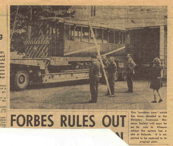
Newspaper, The Courier Ballarat, Ballarat Scrubber tram loaded on a truck, 22/09/1971
Yields information about the dispersal of tramcars after the closure of the Ballarat system, in particular the scrubber tram to the TMSV.Newspaper clipping from The Courier, Ballarat, 22/9/1971 with a photo and caption of the Ballarat Scrubber tram loaded on a truck prior to being transported to Bylands for the TMSV. Photo shows a worker with a long pole to prop up the overhead so the truck with load could clear the depot area. See Reg Item 3776 for a print of the Courier photograph.scrubber tram, tmsv, transport -
 Ballarat Tramway Museum
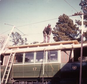
Photograph - Colour Print, Lilian Butler, 20/09/1971 12:00:00 AM
Yields information about the disposal of tramcars from the SEC Ballarat system to the TMSV following closure.Colour print of Ballarat tramcar 17, being prepared for loading at the SEC Ballarat depot with poles supporting the overhead and a person (Mr Ward?) standing on the roof of the tramcar. Photo taken 20/9/1971. Item was placed in an envelope marked "Mr. G Ward" - retained with photograph in storage folder. Photo printed on Kodak Paper. Photograph by Lilian Butler?in ink on rear "Tram Depot - Wendouree Parade, Ballarat Monday 20th September 1971. With my compliments Lilian Butlertrams, tramways, tmsv, tram disposal, sec, depot, loading trams, tram 17 -
 Ballarat Tramway Museum
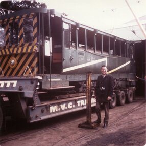
Photograph - Colour Print, Lilian Butler, 21/09/1971 12:00:00 AM
Yields information about the disposal of tramcars from the SEC Ballarat system to the TMSV following closure.Colour print of Ballarat Scrubber tram loaded on a transport truck with Graeme (Graham) Jones standing alongside. Photo taken 21/9/1971. Tram was acquired by the TMSV. Item was placed in an envelope marked "Mr. G Jones" - retained with photograph in storage folder. Photo printed on Kodak Paper. Photograph by Lilian Butler? See btm6444doca for more info about G. Jones. See Reg Item 7889 for a set of 16 photographs of the event by Graham. in ink on rear "Ballarat Tram Depot - Monday 21st September 1971. With my compliments Lilian Butler"trams, tramways, tmsv, tram disposal, sec, depot, loading trams, scrubber tram, tram scrubber -
 Ballarat Tramway Museum
Photograph - Digital image, 1970s
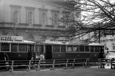
Yields information about the City tramway centre, corner of Sturt and Lydiard St and passengers changing or leaving trams.Digital image of two single truckers (31 and another) off loading passengers at the corner of Sturt and Lydiard St, City centre, with the ANZ bank in the background. No. 31 has a SEC roof advertisement and the other tram, an Eureka Roofing Tiles roof Advert. Photo taken by Peter Bruce 1970's and 1971, prior to the closure of the Ballarat tramway system. Peter's Title of image: "Change here"trams, tramways, sturt st, city, anz, tram 31 -
 Ballarat Tramway Museum
Photograph - Digital image, Peter Bruce, "No. 41 Loading for Sebas", 1970s
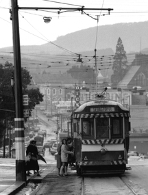
Yields information about the stop in the City on the south side of Sturt St and loading passengers.Digital image, black and white, of No. 41 loading passengers for Sebastopol at the city terminus. A number of passengers, including one carrying an umbrella are boarding. Shows the signage at the city stop. In the background is Bridge St, looking along to Victoria St and Mt Warrenheip. Another tram is in Bridge St. Photo taken by Peter Bruce 1970's and 1971, prior to the closure of the Ballarat tramway system. Peter's Title of image: "No. 41 Loading for Sebas"trams, tramways, city, sturt st, bridge st, sebastopol, tram 41 -
 Ballarat Tramway Museum
Photograph - Ballarat tram 17 on a low loader, A G Culpeffer Cooke, 20/9/1971
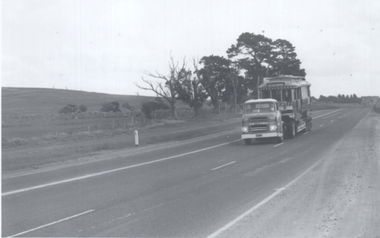
Black and white photograph of tram 17 on a low loader being transported to the TMSV site at Bylands on 20/9/1971, following the closure of the SEC System. A similar photograph appears in the Oct. 1971 issue of the TMSV Running Journal.Yields information about the move of Ballarat 17 to Bylands in Sept. 1971.Black and white photograph with photographers details on the rearStamp on the rear "WELT Collection, A G Culpeffer Cooke Victoria Australia, Ref... Date Sep 1971"trams, tramways, tram 17, tmsv, transporting trams -
 Ballarat Tramway Museum
Newspaper, Bendigo Advertiser, "Somebody tries to "pinch" a Birney", 24/10/1972
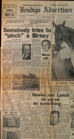
Newspaper report on the issue of the disposal of former SEC Bendigo trams following the closure of the system. The Adelaide-based tramway museum (AETM) was allocated Birney No. 29 by the SEC and agreed to by the Minister for Fuel and Power Mr Balfour. When they tried to collect it, the loading was stopped, with the agreement of the City of Bendigo, quoting Mayor Cr J P Pearce. The newspaper gives the background to the issue of the retention by Bendigo of the former SEC fleet. Following this action, no other tramcars that had been allocated at the time left Bendigo. In 1975, the Government paid the Bendigo Trust to reconstruct a Birney that had been scrapped before the closure of the Bendigo system which was given to the AETM. See the AETM website for further details - tram 303. Story by Barry Cail. See item 8779 for the Herald Sun report of the same date. On the bottom left-hand corner of page 2, (see second image) is an item titled "Question on Tourist Trams", outlining several questions that Mr Floyd (Labour, Williamstown) will ask the Minister of Transport Mr Wilcox about the operation of Tourist trams, safety and insurance, and whether tourist trams will run in Ballarat.Yields information about the Bendigo system following closure and the retention of tramcars.Newspaper - page 1 of The Bendigo Advertiser 24/10/1972 - newsprintbendigo, tramcars, aetm, birney tramcars, tram 29, tram 303, adelaide, tramcar disposals, ballarat, tourist trams, safety -
 University of Melbourne, Burnley Campus Archives
Plan - Plans and photographs, Burnley Low Energy Greenhouse, c. 2008
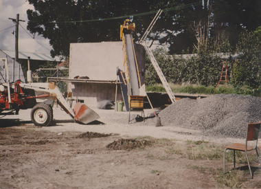
Laminated plans for greenhouse (1) Burnley Low Energy Greenhouse, (2) Solar Boosted Heat Pump - Greenhouse Bench Heating System. C photographs pasted on cardboard and labelled (3) Loading 20 mm gravel into Rock pile. (4) Reinforcement at Bottom Gravel level. (5) Sealing the Top of the Rock pile. (6) Top of Rock pile Before A-Frame Construction. (7) Corner Detail of Portal Frame. (8) Glazing Frames for Solar Panels. (9) Structure Partially Clad, with Solar Panel Supports at Rear. (10) Back of Solar Panels in Place. Laminated C photographs pasted on cardboard and labelled. (11) Burnley Low Energy Greenhouse. (12) Greenhouse Covering Materials Burnley. Pamphlet (13) Burnley College Institute of Land and Food Resources (slightly damaged)burnley, greenhouse, solar energy, construction, pamphlet -
 University of Melbourne, Burnley Campus Archives
Plan - Colour prints, Burnley Low Energy Greenhouse, c. 2008
Laminated plans for greenhouse (1) Burnley Low Energy Greenhouse, (2) Solar Boosted Heat Pump-Greenhouse Bench heating System. Photographs pasted on cardboard and labelled (3) Loading 20mm gravel into Rockpile. (4) Reinforcement at Bottom Gravel level. (5) Sealing the Top of the Rockpile. (6) Top of Rock pile Before A-Frame Construction. (7) Corner Detail of Portal Frame. (8) Glazing Frames for Solar Panels. (9) Structure Partially Clad, with Solar Panel Supports at Rear. (10) Back of Solar Panels in Place. Laminated photographs pated on cardboard and labelled. (11) Burnley Low Energy Greenhouse. (12) Greenhouse Covering Materials Burnley. Panphlet (13) Burnley College Institute of Land and Food Resources (slightly damaged)greenhouse, burnley, low energy greenhouse, solar boosted heat pump, greenhouses, bench heating system, rockpile -
 Diamond Valley Vietnam Veterans Sub-Branch
Weapon - L1A1 SLR Rifle, c2010
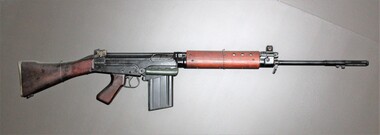
The L1A1 SLR rifle was the first 'best friend' for infantry and other elements of the Australian Armed Forces; the rifle was the closest focus for troops during training and drill.The L1A1 SLR rifle was often the survival factor for troops in a combat situation hence it was treated reverently by the soldier and kept in best working order even in extreme circumstances.LiA1 SLR Rifle. Known as the L1A1 SLR (Self Loading Rifle) and is known for is straightforward fieldstripping and robust nature. The L1A1 is the British version of the Belgian FN FAL rifle. The L1A1 is a reliable, hard-hitting, gas-operated, magazine-fed semi-automatic rifle. The weapon was extensively used by the Australian Infantryman. The L1A1 SLR rifle was the initial general issue to infantrymen and other elements of the Armed Forces. L1A1 SLR (Self Loading Rifle) Type: Battle rifle Wars: Cold War, Vietnam War, Falklands War Designed: 1951 Manufacturer: Fabrique Nationale (FN) Number built: Over 1 million Weight: 4.0–4.96 kg (8.8–10.2 lb) Length: 1,090 mm (43 in) Barrel length: 533 mm (21 in) Cartridge: 7.62 mm NATO Rimless Calibre: 7.62 mm (.308 in) Action: Gas and return spring operated, tilting block Rate of fire: 20 rounds/min semi auto Muzzle velocity: 823 m/s (2,700 ft/s) Effective range: 600 m (656 yd) Feed system: 20-round detachable box magazine Sights: Aperture rear sight, hooded post front sight Accesaries bayonet, sling, grenade launcher, telescopic sights Serial No. AD8100176vietnam, vietnam war, diamond valley vietnam veterans sub branch -
 Ballarat Tramway Museum
Photograph - Ballarat Scrubber arrives at Bylands, 21/9/1971
Photograph shows the Ballarat scrubber tram on an MVC transport low loader after arriving at TMSV Bylands site on 21/9/1971. Not known who took the photo. See item 3776 for a photo of the loading of the tram.Yields information about the transport of the Ballarat Scrubber tram to Bylands following closure of the SEC Operated tram system.Black and white photograph on plain papertramcars, trams, scrubber, bylands, tmsv, transporting trams -
 Moorabbin Air Museum
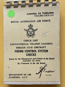
Manual (Item) - (SP) AAP 7213.001-33CL-1-1 Firing control system checks conventional weapon loading on Mirage 111-0 aircraft
... Manual (SP) AAP 7213.001-33CL-1-1 Firing control system ... -
 Moorabbin Air Museum
Manual (Item) - (SP) AAP 7211.001-33CL-1 Checklist Conventional Ordnance Loading Nomad Firing Control System Checks
... Ordnance Loading Nomad Firing Control System Checks ... -
 Moorabbin Air Museum
Manual (Item) - (SP) AAP 7211.022-016-33CL-1 Checklist Conventional Ordnance Loading Nomad Firing Control System Checks
... Ordnance Loading Nomad Firing Control System Checks ... -
 Ballarat Tramway Museum
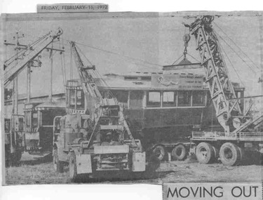
Newspaper, The Courier Ballarat, "Moving Out", 11/02/1972
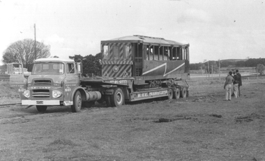
... system. Kaniva Loading Trams Transporting Trams Disposal ...Clipping titled "Moving Out" about the loading of Ballarat Tram No. 30 to go to Kaniva. Acquired by the Kaniva Lions Club. Photo shows three cranes loading the tram onto the truck at the SEC's Ballarat North yard where it had been stored. Cutting date Secured to the top of the cutting with adhesive tape. One of large group of newspaper cuttings from John Bainbridge, 7/4/02. Item has been folded for inclusion within a scrap book. Has a piece of plain paper Secured to the back of the portion that was not Secured to the scrap book itself. See Reg Item 6615 for photographs at Kaniva.Yields information about tram 30 and its stay at Kaniva following the closure of the SEC operated Ballarat Tram system.Newspaper clipping from The Courier, Ballarat, dated 11/2/1972.kaniva, loading trams, transporting trams, disposal -
 Vision Australia
Education kit - Object, Grade I Braille For Sighted People: an introduction to reading and writing Braille, 2001
In 2001 RBS and RVIB worked on a joint project to assist sighted people to learn Grade 1 Braille. This CD-ROM was produced to enable people to be able to learn and practice at home.1 CD-ROM with text and BrailleNot all keyboards are suitable for use with this program. To gauge usability launch Notepad or Wordpad and press the s, d, f and j, k, l keys simultaneously. If all six letters appear your keyboard can be used as a virtual brailler. Minimum system requirements: 32MB of Ram; Pentium 166mhz; Microsoft Internet Explorer 4.0; Quicktime Browser plugin and Macromedia Flash plugin (included in installation). NB: Video may take one minute to load. Display: At least 800 x 600, high colour (16 bit). Installation: The CD-ROM will automatically run the setup procedure. For best results run the program from your hard drive. If the setup fails to start automatically, double click My Computer or Windows Explorer, double click the CD-ROM drive icon, then double click the setup icon. This CD-ROM is a joint project by the Royal Blind Society and Royal Victorian Institute for the Blind.royal blind society of new south wales, education, royal victorian institute for the blind -
 Melbourne Tram Museum
Document - Tender Document, Melbourne & Metropolitan Tramways Board (MMTB), "Tender Schedule for All-Electric Trams - Contract 2500", Jul. 1972
Comb bound (white plastic) specification or tender document, approx. 70 pages, with glossy card covers, titled "Tender Schedule for All-Electric Trams" and "Contract 2500", published by the Melbourne and Metropolitan Tramways Board, closing Monday 2 October 1972. Details the conditions of tender, conditions of contract, notes, specification, gives background information about Melbourne, dimensions, performance, drivers and conductors, trucks, wheels, brakes, electrical equipment, control panels and drawings. The drawings give a map of the system, typical city route, Glenferrie Road route (grade diagram), concrete track construction, min. radius curves, loading gauge, all-electric tram and mounting details for the trolley base, schedule of prices, tender form, form of contract, schedule of information to be provided by the tenderer. On the inside of the cover is a memo from D. Snell, Deputy Chairman to the Testing Engineer, dated 11/7/1972 about the tender being issued, but requesting least publicity and all enquiries to Mr. Snell. Part of the work to tender for the construction of Z class trams. Document scanned to pdf file word searchable. See Item 4388 for the Z3 document and 1583 for an August 1966 version and Reg item 4667 for a draft June 1965 version. 2nd copy added 7/8/2020 from Keith Kings papers.In in pencil in the top right hand corner of cover "1975" crossed out and "1972" written in. On first sheet in pencil, "Howard Smith" and "Laboratory 10 Feb 1975" stamped on.trams, tramways, specification, tenders, z class, mmtb, melbourne -
 Melbourne Tram Museum
Document - Tender Document, Melbourne & Metropolitan Tramways Board (MMTB), "Design, Manufacture and delivery of 100 only all-electric trams", Aug. 1966
Comb bound (white plastic) specification or tender document, approx. 70 pages, with glossy card covers, titled "Tender Schedule for All-Electric Trams", published by the Melbourne and Metropolitan Tramways Board, closing 12 September 1966. Details the conditions of tender, conditions of contract, notes, specification, gives background information about Melbourne, dimensions, performance, drivers and conductors, trucks, wheels, brakes, electrical equipment, control panels and drawings. The drawings give a map of the system, typical city route, Glenferrie Road route (grade diagram), concrete track construction, min. radius curves, loading gauge, all-electric tram and mounting details for the trolley base, schedule of prices, tender form, form of contract, schedule of information to be provided by the tenderer. Second copy from same donor added 9-3-2017 See Reg Item 2266 for the 1972 version and 4667 for a draft version - dated June 1965. See Item 4388 for the Z3 document. See Reg Item 4049 for associated newspaper cuttings.In red felt pen on top right hand corner "(1966)". Has stamp "Discarded from PTC Library 22 Oct. 1989" on front cover. 2nd copy has "1966" in ink in top right hand corner.trams, tramways, specification, tenders, z class, mmtb, melbourne -
 Melbourne Tram Museum
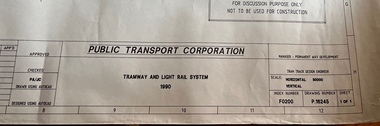
Drawing, Public Transport Corporation (PTC), Tramway and Light Rail System - P16245, 1990
Drawing shows the layout of the Melbourne tram system in 1990. Has a detail for the City area, prior to the expansion into Docklands and relocation of Batman Ave. Legend shows safety zones, loading zones, tram stops and substations, along with details of intersections, curves and crossovers.Yields detailed information about the Melbourne tram system layout in 1990.Dyeline print of drawing PTC drawing No. P16245tramways, tram stops, map, light rail, substations -
 Melbourne Tram Museum
Document - Specification, Melbourne & Metropolitan Tramways Board (MMTB), "Design, Manufacture and delivery of 100 only all-electric trams", Jun. 1965
Specification or Tender Document - titled "Design, Manufacture and delivery of 100 only all-electric trams", and "Background Information and Preliminary Specification", dated June 1965. Bound into a brown foolscap card cover. Details the conditions of tender, conditions of contract, notes, specification, gives background information about Melbourne, dimensions, performance, drivers and conductors, trucks, wheels, brakes, electrical equipment, control panels and drawings. The drawings give a map of the system, typical city route, Glenferrie Road route (grade diagram), concrete track construction, min. radius curves, loading gauge, all-electric tram and mounting details for the trolley base, schedule of prices, tender form, form of contract, schedule of information to be provided by the tenderer. Comprises: 1 - Conditions of Tendering - 1 page 2 - Conditions of Contract - 4 pages 3 - Contents - 3 pages 4 - Notes for prospective tenderers - dated June 1965 5 - General nature of contract - 21 pages 6 - Appendix A - climate data - two sheets 7 - List of 14 appended drawings 8 - O.6887A - cross section of trolley wire 9 - P.13855 - Glenferrie Road, Longitudinal Section 10 - P.13856 - Wattle Park Route 11 - P.13857 - East Preston Route 12 - P13858 - Concrete track construction 13 - P13859 - Open track construction 14 - P.13860 - Paved ballast track construction 15 - P.13887 - Tram Route - locations of substations and section switches 16 - P.13888 - Minimum radius service curves to give minimum clearance between tramcars 17 - P.13889 - Grooved Rail - 102 pounds per yard and tire profile 18 - R10-301 - Loading gauge, proposed electric tramcars 19 - R9706K - Rolling stock data, tramcars 20 - R10306 - Collins Points Shifter - Wiring diagram. 21 - Schedule of data to be supplied by the tenderer 22 - notes on Automatic Points shifters - 2 sheets 23 - Tender prices and delivery periods - 2 sheets. See Reg Item 2266 for the 1972 version and 1583 for the August 1966 version. See Reg Item 4049 for associated newspaper cuttings. See file htd4667i1.pdf for scans of the drawings.In ink in top right hand corner - "Lees"trams, tramways, specification, tenders, z class, mmtb, melbourne -
 Melbourne Tram Museum
Document - Tender Document, Melbourne & Metropolitan Tramways Board (MMTB), "Tender Schedule for 100 Electric Trams Contract No. 3000", Apr. 1977
Comb bound (white plastic) specification or tender document, approx. 180 pages, with glossy card orange covers, titled "Tender Schedule for Electric Trams" and "Contract 3000". Compiled and published by the Melbourne and Metropolitan Tramways Board, closing Monday 10 May 1977. Details the conditions of tender, conditions of contract, notes, specification, gives background information about Melbourne, dimensions, performance, drivers and conductors, trucks, wheels, brakes, electrical equipment, control panels and drawings. The drawings give a map of the system, typical city route, Glenferrie Road route (grade diagram), concrete track construction, min. radius curves, loading gauge, all-electric tram and mounting details for the trolley base, schedule of prices, tender form, form of contract, schedule of information to be provided by the tenderer. Includes an Alphabetical Index. Includes a drawing for a single ended version of the tramcar. Became the Z3 class. Only the table of contents and the drawings scanned. See Reg Items 1583 and 2266 for other similar documents. See Reg Items 337 and 338 for a report on the operation of single ended tramcars 2 copies held.Has in ink written on front cover "J Armstrong" with a stamp blacked out and other copy of the same signature.trams, tramways, z3 class, specification, tenders, mmtb, melbourne, single ended tramcars -
 Ballarat Tramway Museum
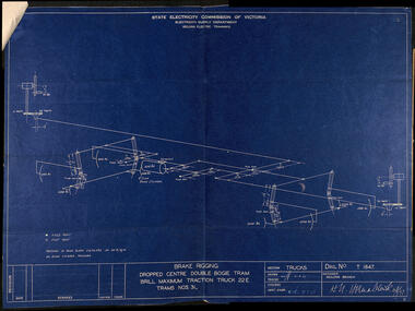
Drawing, State Electricity Commission of Victoria (SECV), "Brake rigging dropped centre double bogie tram Brill maximum traction truck 22E, Trams Nos. 31,", Aug. 1947
Drawing details brake rigging and dimensions for a Brill 22E truck. Dated 4/8/1947, prepared by the SEC Geelong branch, signed by H N Hornabrook 6/8/47 showing the layout and loads on each part of the brake system, drawing No. T1647. See item 9025 and 9857 for other versions.Yields information about the brake rigging for Brill 22E trams and demonstrates the activities of the SEC Geelong office.Drawing - blueprint, titled "Brake rigging dropped centre double bogie tram Brill maximum traction truck 22E, Trams Nos. 31,""D1775" in ink on top sheet right hand corner.brill 22e, drawings, brake rigging, geelong -
 Ringwood and District Historical Society
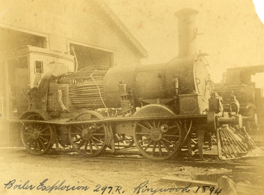
Photograph, Boiler explosion at Ringwood station 20th June 1894 for engine 297R. "Heard in Box Hill"
Black and white photographs - 2 copiesTyped below photograph, "Boiler explosion at Ringwood station 20/6/1894. Heard in Box Hill". Article from newspapers:- Weekly Times (Melbourne, Vic. : 1869 - 1954), Saturday 27 January 1894, page 21 Official enquiry. The Board of Enquiry appointed by the Railway Commissioners to enquire into the causes of the boiler explosion which shattered the locomotive at Ringwood on Saturday night, assembled at the Railway department on Wednesday to commence its deliberations, The board consisted of Mr R. Fulton, engineer, C. W. McLean; engineer to the Marine Board, and Mr Mephan Ferguson, iron-founder. There is some difficulty at the outset about the constitution of the board; It was suggested that the Apt of Parliament contemplated that boards of experts, after the manner of the present one, needed, to have their appointments confirmed by the Governor-in-Council. The point, however, was not considered sufficiently important to prevent the board from proceeding with evidence. Robert Greyford, stationmaster at Ringwood, was the first witness. He said he saw the explosion on Saturday night at about twenty minutes to 8. There was a rush to the engine to see what had happened, and the driver and fireman were both found on the platform of the engine. The driver seemed badly hurt, but the fireman, to all appearances, was not so badly injured. They were both attended to and sent up to Melbourne by the last suburban train. Witness had a look at the engine and found the dome and all the plates round the boiler blown clean, away. The springs were also blown clean away. The Chairman (Mr Fulton) : Did you measure the distance ? Witness: Yes; one of the plates was 209 yards away. A piece from the top of the boiler 15 pounds in weight he found driven into the hard beaten track 410 yards away. Several pieces of boiler plate were found scattered at various distances. The buildings roundabout were injured. The Chairman; Did you notice anything peculiar about either of the driver or the fireman ? — No ; nothing wrong, with either of them. If the engine was blowing off at all, it must have been very light. In your opinion, were they perfectly sober ? — Perfectly. In approaching the station, is there a down or an up grade? — A very slight down grade. How is the road from Healesville ? — Up and down all the way. It is down, grade for about 200 yards coming into Ringwood station. They shut off ; steam about a quarter of a mile away, and come in at a good pace. They generally put on 15 pounds of steam while they are in the station. Mr Ferguson : Had the driver the usual load on ? — Yes ; about the usual load. Witness added that he had known the driver personally for about 10 years, and he had always been a careful, steady, sober man. He did not know the fireman so well. John Palmer, porter at Ringwood station, also saw the explosion. He was attending to the train on its arrival. He was knocked down by the force of the explosion. When he got up he saw the engine driver being carried into the office covered in blood. He noticed nothing peculiar about the driver and fireman, nor about the engine. Mr McLean : How far were you from the engine when you were knocked down ? — From ten to fifteen yards. William Paul, the guard of the train to which the injured locomotive Was attached, said he was looking at the engine at the very moment the explosion occurred. It seemed to come from exactly under the dome. The force of it took him off his feet. He was about 15 yards from the tender. When he rose he tried to reach the engine, but could not do so on account of the steam and coal dust. He called out to know whether any of the passengers were injured, and got no response, so that he concluded they were all right. All the lamps but about half dozen were extinguished by the force of the explosion, although the glass was not broken. He could testify most distinctly that the driver and fireman were both sober. The driver was a man who never drank. The steam started to blow off about a minute and a half before the explosion took place. The last place at which the engine took water was Healesville. The Chairman : Do yon know anything of the quality of the water there ? Is it creek water ? — Yes ; it comes from the Graceburn River. You never heard of its quality ?— No. How long have you known this engine on the road— About 13 months. Hew long have you known the driver on this line ? — About six weeks. I have known the fireman several years. The driver was a strict teetotaller, and I never saw the fireman take anything to drink in his life. Mr T. H, Woodroffe, chief mechanical engineer of the Victorian Railways, produced a report he had written to the secretary, about this explosion. The document gave facts concerning the engine and the explosion. It stated that the rapture seemed to have occurred at the rim of the plates adjoining the fire box. The engine was built at the Phoenix Foundry, Ballarat, in 1883. It was repaired at various times, the last time being in July of last year when it was sent to the Port Melbourne shops, and was then tested to a cold water pressure of 195 and found all right. It was the custom to overhaul all locomotives about every five years. The Chairman : There were no very heavy repairs in July, 1893; were there? — Not to the boilers. The shop manager's report says that the plug and safety tap holes were repaired, five new copper studs put in firebox, ash-pan door repaired, tender cleaned and overhauled, and studs re-rivetted, and boiler tested to pressure of 195, cold water. Mr Woodroffe read the report of the repairs effected to the boiler in December, 1888. That would be the time the plate was put in the boiler. On that occasion three new plates were put in the bottom and the boiler tested up to 195. The Chairman: Do you keep a record of the water used ?— Yes, the water in this case, I think, came from the Maroondah scheme. Mr Woodroffe said boilers were examined front time to time in the running sheds. In his opinion every possible care had been taken to keep the engine in proper care. There might, however, be lessons learnt from this. The Chairman: No doubt. From his examination of the plates [the] witness did not think the state of them could have been detected from the outside. There were no signs of leakage or sweating or anything of that sort. The next witness- was Walter Stinton, workshop manager at Newport and he said that the injured engine had been repeatedly repaired under his charge. He gave a technical account of the repairs effected on various occasions. The testing of locomotives was under his special notice. They had a high pressure pipe running; round the works, and a pump set at 2001b. When the boiler was pumped full of water the pressure when applied up to 1951b. The board appointed by the department to inquire into the Ringwood locomotive boiler explosion sat again at Spencer street on 25th inst. Mr R. Fulton presided and the other members of the board were. Mr Mephan Ferguson and Mr C. W. McLean. Charles Grubb, foreman of the boiler-makers at the Newport workshops, said he had inspected the pieces of plate that had been blown out of the engine, and after examining them, pointed out to the Chief Mechanical Engineer the portion where the plate had started to burst. It was under the lap, on the right hand side of the boiler. The grooving might be accounted for by bad water. During the past twenty years he had examined all the boilers that came into the Williamstown workshops, and while some were hardly marked at all, others were very badly eaten away. The practice was to cut out the defective portions. In this case the boiler was repaired in a similar manner. The Chairman : Can you suggest any other way of repairing so as to prevent accident ? — No, unless by taking out a plate on one side from the joint, and carrying it further up so as to avoid the joints meeting, or by taking out the plate altogether. What would.be the cost .of putting in a new " plate I—Perhaps about double the price; but I wouldn't recommend that course. It would be putting a new plate against plates that have been in use ten years or so and that would not be advisable. I think the present system better. I consider the present system of repairing the best. This is the first we have had so bad like that, to my knowledge. You attributed this to bad water. Is there no other probable cause ? — Well; unless the iron be bad. This was Lowmoor iron. I think this accident was caused by the eating away of plates. This one was the worst I have seen, for the short time it had been running. We use three classes of iron — Lowmoor, Monkbridge and Bowling. By Mr Woodroffe (Chief Mechanical Engineer) ; There are engines still running that were repaired at the same time as this one, in 1888, and. in the same way. These are engines 339 and 333. They have been recently examined and are in splendid order. What in your experience, is the age of a boiler on the Victorian railways? — From 17 to 20 years our earlier boilers stood. The later boilers don't stand so well. How is that? — There is difference in construction, and the material is lighter. The old boilers had thicker plates. Have you been asked in any way to curtail boiler affairs? — No, sir; nor in any way. You have never hesitated to carry out any necessary repairs? — Never. Our orders have been to exercise every care in examining, repairing and renewing boilers. Witness said that his practice was when an engine came into the workshop to find out how long she had been running. If over five years, he informed the workshop manager, and they thought it necessary the tubes were taken nut. If everything was in good order witness reported to the manager. The cost of taking out the tubes and putting them in again was about L20. Mr Woodroffe : Have you ever hesitated to repair a boiler on the score of expense ? — No, never. Mr McLean : Hew do yon ascertain whether a boiler requires repairs?— I keep a record of every boiler examined. From every boiler that comes in I have the dome covers taken off, and when it is practical I get inside. l can almost tell from the top of a boiler what the bottom is like. If there is any doubt about it I have the tubes taken out. If I have suspicion of defective plate I cause to have bored a triangle in the plate at the point where there is the most wear. There is a travelling inspector who visits all the running sheds of the colony except Port Melbourne and tests the boilers. He reports to us and we note what he points out. Alfred Thompson, locomotive inspector of the eastern section, said he knew this engine, 297R. He read a list of her repairs. He heard of the accident on Saturday night and went up to Ringwood. The Chairman : Did you ever notice anything peculiar about the engine? — No, I considered her A1 and would not have hesitated to have put on 140lb pressure owing to the repairs she had undergone. Witness considered that the explosion was caused by the expansion and contraction of the plates ; and, no doubt, the plate had been eaten away through bad water. The other side of the boiler showed: signs of corrosion: By Mr Woodroffe ; Is every care taken with the boilers ? — Yes, every possible care is taken for the safety of boilers, Weekly Times (Melbourne, Vic. : 1869 - 1954), Saturday 27 January 1894, page 7 EXPLOSION OF A LOCOMOTIVE BOILER, NARROW ESACPE FROM FATALITIES. THE DAMAGED ENGINE. [See drawing of loco – saved in “Railways” folder] The explosion of a locomotive boiler at Ringwood on Saturday evening, formed the subject of much discussion in railway circles on Monday. The Minister arrived at the office at an unusually early hour and immediately entered into a consultation with the acting chairman, Mr Kibble, and Mr Commissioner Murray. As the result of the interview it was resolved to ask three gentlemen of acknowledged engineering experience to sib as a board with the . object of inquiring into the cause of the accident and furnishing a report. Mr Richardson and the Commissioners are tally seized of the importance of having a searching investigation into the accident, and, with Mr Murray, the former went to Ringwood to inspect the scene of the disaster. They will he accompanied by Mr Woodroffe. During the morning no official report had come to hand from the driver or fireman of the engine in reference to the accident, but that is thought to be due to the circumstance that they have not sufficiently recovered to be able to give a circumstantial account of what occurred. The engine was one of the old R's, and, Mr Kibble pronounced them to be about the best class of engines used. So far nothing can be said as to the probable cause of the accident, as the broken plating of the engine has not been submitted to the inspection of experts. Weekly Times (Melbourne, Vic. : 1869 - 1954), Saturday 27 January 1894, page 7 STATEMENT BY THE FIREMAN. This morning Thomas Miles, fireman on the engine the boiler of which exploded on Saturday night, is suffering from an injury to the spine, as well as a very severe shaking to the system. He states that he was fireman on the engine attached to the train which left Healesville on Saturday evening, at ten minutes to 8. Everything went all right until Ringwood was reached, when, .just as the train was about to continue its journey, a load explosion took place and Miles remembers nothing more until he was picked np on the platform ; and found himself suffering from a pain in the back, and an injury to his arm. He cannot think of any reason which could have caused the explosion, as there was plenty of water in the boiler, and everything seemed working all right. Mr R. Fulton, consulting engineer, of Queen street; Mr McLean, a member of the Marine Board ; and Mr Mephan Ferguson, engineer, have consented to act as a board to inquire into the cause of the engine boiler explosion at Ringwood on Saturday evening. The board has been appointed under section 117 of Act 1135, which provides that the Governor-in-Council may direct the taking of a such a step. Mr1 Fulton will act as chairman of the board, which met for the first time at the railway offices, Spencer street, this forenoon. Before separating the members of the Board paid a visit to the Prince's Bridge locomotive sheds in company with Mr Woodroffe, the chief mechanical engineer, for the purpose of inspecting the shattered boiler. It has been stated that the explosion is known to have been caused by a flaw in a plate which was put on the boiler about four years ago, but enquiries have tailed to elicit anything in support of that view. The engineers connected with the department are not inclined to say anything on the subject. Weekly Times (Melbourne, Vic. : 1869 - 1954), Saturday 14 April 1894, page 20 The Ringwood Boiler Explosion, The Minister of Railways has received the supplementary report of the board appointed by him to investigate the circumstances connected with the explosion of a locomotive boiler at Ringwood. In their first report the board did not attach blame to anyone. Mr Richardson felt satisfied that the responsibility of having the engines properly inspected and overhauled periodically could be fixed if the inquiry were extended. He therefore referred the matter again to the Board, who took further evidence. In the report now furnished, the Board hold Loco. Inspector Thompson blameable, but point out as a mitigating circumstance that he had not received "written instructions" respecting inspections and overhauls. Weekly Times (Melbourne, Vic. : 1869 - 1954), Saturday 7 July 1894, page 32 The Ringwood Boiler Explosion. The Minister of Railways takes exception to the tone of a paragraph appearing in a morning contemporary respecting the Ringwood boiler explosion. It makes it appear that Mr Richardson has referred the report of the board which considered the facts connected with the explosion to the Crown solicitor simply because he differed from the finding of the board. The Minister explains that when he received the report he found that the responsibility for having boilers properly inspected and overhauled had not been clearly fixed. He personally obtained farther evidence on that point, and arrived at a conclusion, from which the commissioners differed. As he did not like to take upon himself the responsibility of deciding upon the effect of the evidence, he submitted the matter to the Crown Solicitor, but that officer did not furnish him with the information sought. He has, therefore, referred the question to the Attorney-General, together with the draft of a regulation respecting boiler inspections and overhauls in the future. Mr Richardson says that his whole aim is to have the responsibility positively fixed. Weekly Times (Melbourne, Vic. : 1869 - 1954), Saturday 28 April 1894, page 23 The Minister of Railways has completed his consideration of the supplementary report received by him from the Ringwood Boiler Explosion Board. The report, it will be remembered, held Loco-Inspector Thompson blameable for the non-inspection of the boiler, but considered there was extenuating circumstances. There was a certain amount of doubt as to the absolute instructions given for overhauling engines periodically. Mr. Richardson is sending the report on to the Commissioners with instructions that the responsibility respecting inspection of boilers shall be made clear for the future.