Showing 381 items
matching operating systems
-
 Ballarat Tramway Museum
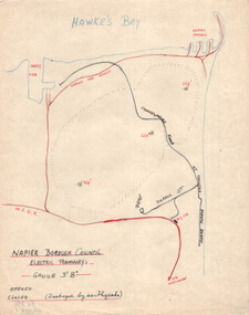
Drawing - Napier NZ - Plan and Notes, Wal Jack, c1947
... . The reference states that the system operated from 1913 to 1931. Based.... The reference states that the system operated from 1913 to 1931. Based ...Wal Jack had an extensive range of correspondents throughout Australia and the world who often provided him with detailed drawings and notes on various tramway systems. This set of notes on the Napier NZ tramway system provides details of the tram system and a list of the rolling stock. Notes that the system was destroyed by an earthquake, but he did not know the opening and closing dates at the time of preparation. The reference states that the system operated from 1913 to 1931. Based on the handwriting, prepared by Wal Jack himself. Yields information about Wal Jack's extensive recording and research work.Drawing - black, red and blue ink or colour pencil and a second sheet, both on quarto paper providing details of the Napier NZ tramway system.tramways, wal jack, drawings, maps, tramcars, napier -
 Ballarat Tramway Museum
Manual - The Melbourne Electric Supply Co. Service and Wiring Rules, Melbourne Electric Supply Co. (MESCo), 1918
... to Geelong and operated the Geelong Tramway system. MESCo Geelong... to Geelong and operated the Geelong Tramway system. MESCo Geelong ...The Melbourne Electric Supply Co. operated a Power Station in Richmond and provided power to the Prahran and Malvern Tramways Trust and the Hawthorn Tramways Trust. They also provided power to Geelong and operated the Geelong Tramway system. MESCo Geelong and Richmond operations were taken over the SECV in 1930. The book gives the requirements for wiring of building and switchboard. Yields information on the electrical requirements that electricians were required to work to where MESCo supplied electricity. It would have been used in the development of the SEC rules. Has a strong association with one of the MESCo Electrical Inspectors.Book - The Melbourne Electric Supply Co. Service and Wiring Rules - 64 pages, centre stapled, dark fawn covers. Provides rules for the Melbourne (Richmond) and Geelong undertakings. Dated 1/4/1918. Has a number of printed updates pasted into the book along with a typed and hand witten note. Price 6d. Has an index.Some hand written notes on the various clauses. Has the stamp of "Electric Inspector" in the top right hand corner. Numerous marks of red and blue pencil to high light specific clauses.rules, wiring, electrical, regulations, mesco, geelong, tramways -
 Melbourne Tram Museum
Document - Report, Parliament of Victoria, "Report of the Royal Commission - Railway and Tramway systems on Melbourne and Suburbs", Nov. 1911
... tramways operating, cable system and operational stats, the current... into and report upon the Railway and Tramway systems on Melbourne ...Report - 42 pages, 3 sections, stapled on the left hand edge, titled "Report of the Royal Commission appointed to inquire into and report upon the Railway and Tramway systems on Melbourne and Suburbs" - dated 1911. Looks at the state of the Suburban rail system, finances, electrification's, costs, evidence of Mr. Merz, advantages of the electrification, power supply and standards, whether AC or DC, duplication, Glen Iris line, conclusions and recommendations. Tramway - summarises the current tramways operating, cable system and operational stats, the current tramway systems, other cities, relative merits, future tramways for Melbourne, operational speeds, use of cable conduits for electric traction, conversion, municipal control , control of the tramways by the railways, a general scheme, formation of a larger tramway trust and its management, purchase of the cable tramways and recommendations. Note: This document is available as a pdf on the Parliament of Victoria website. 2nd copy added 2-1-2019 from donation of Norm Cross.In ink in the top right hand corner "TB"trams, tramways, tramways, cable trams, finances, conversion, railways, royal commission, costs -
 Ballarat Tramway Museum
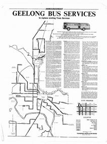
Poster, Transport Regulation Board, "Geelong Bus Services", late 1955
... Electricity Commission of Victoria operated Geelong Tramway system... Commission of Victoria operated Geelong Tramway system. Gives details ...Yields information about the closure of the Geelong Tramway system and the bus replacements made by the Transport Regulation Board, can be compared to that for Ballarat.Poster printed on off white paper with a gloss finish on the printed side - Produced shortly before the closure of the State Electricity Commission of Victoria operated Geelong Tramway system. Gives details of the replacement bus services as well as the existing bus services and other changes planned. Provides notes on the operator, timetables, fares, vehicle standards and dates when the services would be changed. Map shows Operator, section points, rail lies and service levels. Authorised by the Secretary of the Transport Regulation Board E V N Field. pdf file has to be opened outside dbTextWorks.trams, tramways, geelong, closure, map, buses -
 Ballarat Tramway Museum
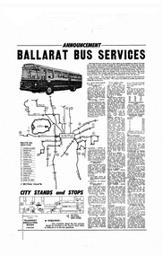
Poster, Transport Regulation Board, Ballarat Bus Services", Aug. 1971
... Electricity Commission of Victoria operated Ballarat Tramway system... Electricity Commission of Victoria operated Ballarat Tramway system ...Yields information about the closure of the Ballarat Tramway system and the bus replacements made by the Transport Regulation Board, can be compared to that for Bendigo and Geelong.Poster, titled "Ballarat Bus Services" printed on off white gloss paper. Produced shortly before the closure of the State Electricity Commission of Victoria operated Ballarat Tramway system. Gives details of the replacement bus services as well as the existing bus services and other changes planned. Provides notes on the operator, timetables, fares, route numbers and dates when the services would be changed. Map shows the bus routes, route numbers, section points and City stands and stops. Authorised by the Secretary of the Transport Regulation Board B. P. Kay. pdf file has to be opened outside dbTextWorks.trams, tramways, ballarat, map, closure, buses -
 Ballarat Tramway Museum
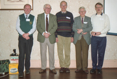
Photograph - Digital Image - BTPS Original Committee Members, 19-9-1992
... -operated Ballarat Tramway system. Richard Gilbert, Melton Foo... of the closure of the SEC-operated Ballarat Tramway system. Richard ...The image is of five of the original BTPS Founding Committee at the 21st-anniversary dinner of the closure of the SEC-operated Ballarat Tramway system. Richard Gilbert, Melton Foo (deceased), Neville Gower (deceased), George Netherway (deceased), Paul Nicholson. Image of Melton Foo plaque and reference to George Netherway supplied by Paul. Neville Gower, foundation Secretary, passed away 9-11-2006 - see Dec 2006 Fares Please! Melton Foo - see Jan 1995 Fares Please! and for George and Noelene see May 1999 Fares Please! Yields information about the original BTPS Committee who were still active in the organisation during 1992.Digital image from Paul Nicholson of the members of the original BTPS Committee at the 21st anniversary dinner held at the Gardens Lake Lodge on 19/9/1992. btps, 21st anniversary, dinner, richard gilbert, melton foo, neville gower, george netherway, paul nicholson -
 Melton City Libraries
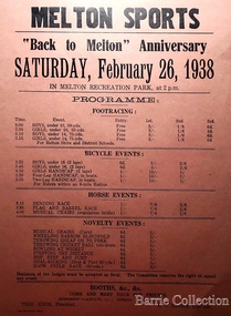
Programme, Melton Sports Programme, 1938
... an important part in the establishment of the sports. A handicap system... an important part in the establishment of the sports. A handicap system ...In 1937 in October the first Melton and District School Sports began. The schools in the area annually competed for a shield donated by the Express newspaper. MrGoodacre contributed an important part in the establishment of the sports. A handicap system operated enabling very small schools to compete fairly. My father E.W. Barrie was responsible for the public address system for many years. The events were Flat race (40, 50, 60, 70, 80, and 100 yards) Long jump, High jump, Skipping race, Potato race and Flag relays making a total of 30 events. Programme of various sport events held at Melton Recreation Parkeducation, sport -
 Bendigo Military Museum
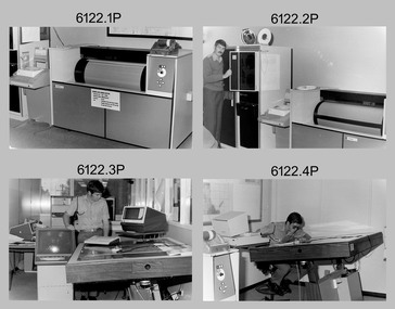
photograph - AUTOMAP 1 Production – Army Survey Regiment, Fortuna, Bendigo, c1980
... ) - Photo, black & white, c1980, 1130 Operating System..., 1130 Operating System administration, SGT Denis Marshall. .16 ...This collection of 20 photos was most likely taken in 1980. The AUTOMAP 1 computer assisted cartography and mapping system was introduced in 1975. The components of AUTOMAP 1 were the Input Sub-System of four Wild B8s stereoplotters and three Gradicon digitising tables, the Optical Line Following Sub-System – Gerber OLF, the Verification Sub-System – Gerber 1442 drum plotter, the General Purpose Sub-system – HP21MX computer and the Output Sub-System – Gerber 1232 flatbed plotter). The first map was published in 1978 (Strickland 3665-3, 1:50,000). AUTOMAP 1 was the first computer assisted cartography and mapping system utilised by the Survey Corps and was the first system used by Australian mapping organisations. The history of the AUTOMAP 1 system is covered in more detail with additional historic photographs, in pages 116-118 of Valerie Lovejoy’s book 'Mapmakers of Fortuna – A history of the Army Survey Regiment’ ISBN: 0-646-42120-4. See items 6410.24P, 6183.19P, 6184.20P, 6200.5P, and 6222.17P for additional photographs of the AUTOMAP 1 system.This is a set of 20 photographs of Air Survey Squadron military and civilian personnel operating AUTOMAP 1 equipment at the Army Survey Regiment at Fortuna, Bendigo, c1980. The photographs were on 35mm negative film and were scanned at 96 dpi. They are part of the Army Survey Regiment’s Collection. Photos .19P and .20P are printed on photographic and scanned at 300 dpi. .1) - Photo, black & white, c1980, Gerber plotter. .2) - Photo, black & white, c1980, Gerber plotter, LT Rob John .3) - Photo, black & white, c1980, Gradicon edit table, SPR Jamie McRae .4) - Photo, black & white, c1980, Gradicon edit table, SPR Steve Linane .5) - Photo, black & white, c1980, 1130 System administration, unidentified. .6) - Photo, black & white, c1980, Wild B8 stereo plotter, SPR Van Dalen? .7) - Photo, black & white, c1980, Wild B8 stereo plotter, SPR Van Dalen? .8) - Photo, black & white, c1980, Gerber Optical Line Follower (OLF). .9) - Photo, black & white, c1980, Gerber OLF. .10) - Photo, black & white, c1980, Gerber OLF. .11) - Photo, black & white, c1980, Gerber OLF. .12) - Photo, black & white, c1980, Gerber OLF. .13) - Photo, black & white, c1980, Data management, CPL Greg Gilbert. .14) - Photo, black & white, c1980, Data management, CPL Greg Gilbert. .15) - Photo, black & white, c1980, 1130 Operating System administration, SGT Denis Marshall. .16) - Photo, black & white, c1980, Programming System, L to R: unidentified, SGT Alan Toogood. .17) - Photo, black & white, c1980, Programming System, L to R: Robert Cox, WO1 Bob Mason, John Dean. .18) - Photo, black & white, c1980, Programming System, L to R: Robert Cox, WO1 Bob Mason, John Dean. .19) - Photo, black & white, c1980, Gradicon edit table, CPL Chris Carter. .20) - Photo, black & white, c1980, Gerber plotter, LT Rob John..1P to .18P - No personnel are identified .19P - ‘CPL Chris Carter’ annotated on backroyal australian survey corps, rasvy, army survey regiment, army svy regt, fortuna, asr, air survey, automap -
 Melbourne Tram Museum
Newspaper, The Age, "Transport: The New Order", "Stupidity of reforms attacked by groups", 7/01/1993 12:00:00 AM
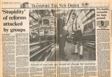
... transport system operated in Victoria including removal... to revise the way the public transport system operated in Victoria ...Newspaper cutting (page 4 of The Age, 7-1-1993), about the proposals by the State Government to revise the way the public transport system operated in Victoria including removal of conductors. Has maps or diagrams showing the proposed changes, including shutting of tram and rail lines and calling tenders for replacement services on country rail lines. Includes headlines: "Transport: The New Order" "Stupidity of reforms attacked by groups" "Advent of machine age means all change for trammies" "Pre-battle scramble for high ground" "Brown attacks massive rorts" Has a photo of conductors Ken Walker and Roberto D' Andrea by Michael Clayton Jones at South Melbourne Depot with W5 874 in the background.trams, tramways, ptc, tramways, melbourne, railways, upfield, closure, buses, unions, public transport, tram 874 -
 Ballarat Tramway Museum
Photograph - Geelong MESCo Bus East Geelong, c1920
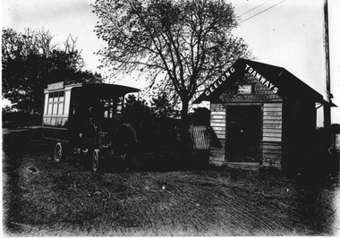
... ), bus at the East Geelong terminus. MESCo operated the Geelong.... MESCo operated the Geelong tram system from 1912 and opened ...The photo shows the Melbourne Electric Supply Co. (MESCo), bus at the East Geelong terminus. MESCo operated the Geelong tram system from 1912 and opened the tram line to this location "East Geelong" in 1923. The terminus was at the Geelong Cemetery, with a wooden waiting room shelter with signage about the building being used for passengers only and prohibiting the posting of bills. The buses ran from the railway station and Moorabool St wharf from 1912 until they were replaced by trams in 1923. The bus is also seen in item 4315. Yields information about the operation of a bus by MESCo in Geelong.Black and white photograph - plain back.geelong, tramways, mesco, buses, east geelong, shelters -
 Ballarat Tramway Museum
Slide - Set of 6, Warren Doubleday, Operation of Ballarat 36 in Melbourne, Sept. 1971
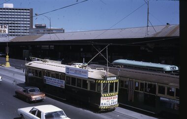
... operated Ballarat tram system. 1 - Outside Flinders St station... operated Ballarat tram system. 1 - Outside Flinders St station ...Photos taken during the operation of Ballarat No. 36 promoting Tourism Week, South St Competitions, Begonia Festival and Sovereign Hill during the week following the closure of the SEC operated Ballarat tram system. 1 - Outside Flinders St station with W2 513 behind - 20-9-1971 2 - tram 1024 promotion Channel O in St Kilda Road - 20-9-1971 3 - tram 36 in St Kilda Road - 21-9-1971 4 - On the King St overoass with W2 390 (Spencer St. route 48) behind - 21-9-1971 5 - Park St South Melbourne, cross over - 21-9-1971 6 - running into South Melbourne Depot. - 23-9-1971 Yields information about the operation of Ballarat 36 in Melbourne for tourism promotion.Set of 6 Kodachrome colour slides - cardboard mounts or green card mount.Have the photographer's slide numbers written on them.trams, tramways, closure, tram 36, ballarat tourism, st kilda road, king st overpass, tram 1024, tram 390 -
 Ballarat Tramway Museum
Newspaper, The Courier Ballarat, Our trams under review - The Courier, Ballarat, 3 and 4 April 1968
... by the Victorian Transport Regulation board into the SEC operated Ballarat... board into the SEC operated Ballarat Tramway system. Enquiry ...Provides information about the two-day enquiry held by the Victorian Transport Regulation board into the SEC operated Ballarat Tramway system. Enquiry held at the Ballarat Court House, by Messrs J Bolster, E V Field (Chairman) and J O Mactier of the TRB. Two photos show the Board and some of the attendees. Page 2 of the 3 April report; the acting assistant manager of the SEC advised that the tramway was unsafe, deaths due to collisions with trams, costs of refurbishing the tracks and tramcars and employment issues. Evidence was also given by the Mayor of Ballarat, Cr. Nicholson, Ballarat Town Clerk Mr Maddern, Barry Wilkins, H A Davis local bus operators. The Board considered whether the existing services could be replaced by private operators, or a publicly operated service, including the cost of operators. Also submissions from Mr O'Shea of the ATOMEA, Ballarat Trams and Labor Council, and Chamber of Manufacturers. At the time, the Government did not have the numbers in the upper house to close the system. Yields information about an 1968 enquiry into the closure of the Ballarat Tramway system. Set of two newspaper cuttings from The Courier, Ballarat 3 and 4 April 1968 about a Transport Regulation enquiry.trams, tramways, ballarat, closure, transport regulation board, trb, enquiry, atomea, sec, secv -
 Running Rabbits Military Museum operated by the Upwey Belgrave RSL Sub Branch
Ikara Missile, Maribyrnong Ordinance Factory in Victoria. et al, 1965
... , these were operated by an actuator system that received flight...Running Rabbits Military Museum operated by the Upwey ...During the 1950’s, the growing threat from Submarines, led the Royal Australian Navy to consider a quick reaction, long range ASW torpedo delivery system as an alternative to the USN’s ASROC and the RN’s Match. Full scale research and development began in 1960 using the Turana target drone as the basis for the delivery platform. Shipboard tests began in 1963 and the Government Aircraft Factory (GAF) began production of three variants M3, M4 and M5 in 1965. The M4 variant had a guidance system designed to interface to a full tactical data handling system while the M3 and M5 variants used a simpler system with a dedicated fire control system. The IKARA is an unmanned miniature aircraft with clip on upper and lower stabilizers and wings. The upper stabilizer (SVU) housed and electronic package that transmitted flight data back to the launch platform and received updated target acquisition data during flight. Flight maneuverability was provided by elevons fitted into the trailing edge of each wing, these were operated by an actuator system that received flight correction data transmitted to the autopilot from the fire control system. The payload, either the Mk44 or Mk46 lightweight torpedo was suspended to the underside of the airframe and faired into the body to provide and aerodynamic shape. The forward section of the body housed the autopilot and the thermal battery unit. Propulsion was provided by the MURAWA steel cased, solid propellant rocket motor with a combined boost and sustainer stage. IKARA was capable of engaging a target to the maximum range of the ships sonar, regardless of weather conditions. Target information is fed into the fire control system, which calculated to drop zone for the torpedo taking into account speed and direction of launch platform and target, win speed etc, then tracking the missile to the drop zone where command signals initiate torpedo release. The IKARA is an unmanned miniature aircraft with clip on upper and lower stabilizers and wings. navy, torpedo, rocket, submarine, missile -
 Bendigo Military Museum
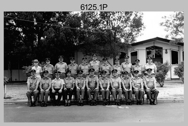
Photograph - Army Survey Regiment’s Officers, Warrant Officers and Sergeants and Squadrons, at Fortuna, Bendigo, 1982
... /plotter, operating the AUTOMAP 1 system and computer programming.../plotter, operating the AUTOMAP 1 system and computer programming ...This is a set of six staff photographs of the Army Survey Regiment’s Officers, Warrant Officers and Sergeants, and each of its four Squadrons at Fortuna, Bendigo in December 1982. Note - Air Survey Squadron’s photo was probably taken in July 1982 as they appear in winter dress. Air Survey Squadron was responsible for aerotriangulation, photogrammetric feature extraction and the AUTOMAP 1 system. Typical tasks were flight planning the acquisition of aerial photography, pugging, mensuration and block adjustments, photogrammetric extraction of topographic features from aerial photography, digital feature editing, map compilation, operating the scanner/plotter, operating the AUTOMAP 1 system and computer programming by civilians. Cartographic Squadron was responsible for the production of the following military products: Joint Operation Graphics, small-scale RAAF Air Charts, large-scale topographic line maps and orthophotomaps. Cartographic technician tasks were scribing, compiling, retouching, masking, type setting, type stickup, terrain embossing, correcting and proving quality control. Headquarters Squadron was responsible for the planning and coordination of map production and contracts. It also performed administrative and support functions such as personnel administration, pay, finance, transportation, records, map Library, kitchens, messes and facility maintenance. It was staffed by Army personnel from RASvy, RACT, AACC, RAAOC and RAEME corps. Other supporting staff at this time included the RAAF Liaison Officer, RAN Liaison Officer and several civilians employed in administration, the Q-Store and grounds maintenance. A component of the Army Svy Regt’s cartographic map production was carried out by the Detachment, a sub-unit located at Bonegilla next to the School of Military Survey. Lithographic Squadron was responsible for the reproduction of map materials and printing of military map products. The main tasks undertaken by photographic technicians were photographic enlargements, reductions and duplication of map reproduction material and processing of aerial photography. Printing technician tasks included platemaking, offset printing, map stock despatching and proofing.This is a set of six staff photographs of the Army Survey Regiment’s Officers, Warrant Officers and Sergeants, and its four Squadrons, at Fortuna, Bendigo, 1982. The black and white photographs were printed on photographic paper and are part of the Army Survey Regiment’s Collection. The photograph was scanned at 300 dpi. No personnel are identified. No personnel are identified. .1P – Annotated on front “OFFICERS MESS DEC ’82” .2P – Annotated on back “SGTS MESS DEC ’82” .4P– Annotated on front “CARTO SQN DEC ’82” .5P– Annotated on front “HQ SQN DEC ’82”royal australian survey corps, rasvy, army survey regiment, army svy regt, fortuna, asr, air survey, carto, litho -
 Federation University Historical Collection
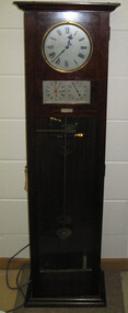
Object, Synchronome Co. Ltd, Synchronome Frequency Checking Master Clock No. 2191, c1930
... and the other is operated by the system frequency. When the clock... and the other is operated by the system frequency. When the clock ...Information from Norman F. Dalton: Ballarat had a reticulated DC supply in the early part of last century and in 1905 had sufficient generating capacity to enable the trams to be changed from horse drawn to DC electricity. The use of electricity increased with the main power station located on Wendouree Parade, near Webster Street, under the ownership of The Electric Supply Company of Victoria. AC generating plant was installed in 1925 and conversion to AC proceeded. In 1934 the company was taken over by the State Electricity Commission Victoria (SECV) and more AC generation was installed and the changeover of customers was accelerated. This is around the time that the Synchronome Frequency Checking Mast Clock was installed at the Wendouree Parade Power Station. The SECV Annual Report of 1921 states: ::Section 11 of the act directed the COmmission to enquire into the question of securing the adoption of such standards of plant and equipment of a system, frequency and pressure for the generation and distribution of electricity as will admit of the efficient interconnection of undertakings throughout the State. In 1934 when the SECV took over the Ballarat operations the question of linking with the State grid had been a planned operation for some years but due to financial considerations had hindered it and in fact would continue to do so for a further 10 years. So while the need for close frequency control for interconnection was hardly an issue, the need to keep electric clocks correct was important, particularly as this item was a frequent sales point to cover the inconvenience and sometimes expense of converting from DC to AC. The clock is a very accurate pendulum clock with provision for varying effective length during operation for precise time regulation. There are two normal time dials and one is controlled by the pendulum and the other is operated by the system frequency. When the clock was in use it was installed by the MEter and Tests Laboratory and the time was checked daily by radio time signals. The two dials were repeated in the operators control panel in the Power Station. A maximum deviation between the two dials was set in the operating instructions (eg 5 seconds) and the operator would correct this when necessary by remote manual alteration of the turbine governor set point. The clock was used to drive and regulate a system of "slave" clocks which were used to display the time in various locations around the power station. A slave clock is a simple clock which is driven by a small electric motor, its accuracy is regulated by the master clock every 30 seconds to ensure that it and all the other slave clocks in the station are on exactly the right time; slave clocks were placed in various locations, from common rooms to workshops. A master clock could potentially run thousands of slave clocks at one plant. The clock also contains a rectifier. A rectifier is a device that is used to convert AC power to more stable DC current.Two clocks in a timber case. Both are electric, one is powered by the main pendulum mechanism, the other is a self contained electric clock. The main mechanism is of the gravity arm and roller type, which sends an impulse to the slave clocks every 30 seconds. The This Synchronome Frequency Checking Master Clock was used at the Ballarat Power Station. Below the main section of the case is a smaller cabinet containing a rectifier to provide consistent DC power for the clock. The rectifier was made by the Victorian company Hilco, which was located in Burwood. There is a high chance this is not the original rectifier from this clock as there appears to be brackets to hold a larger device in the space the rectifier occupies.Front below main clock face on front of case: "Patented Sychronome Brisbane" Lower left-hand clock face: "Frequency time" Lower right-hand clock face: "Standard Seconds" Synchronous electric clock mechanism on door (Frequency time clock): >200/250 V. 50~ >"Synchronomains" Made in England >Direction indicator for clock starting switch >"To start move lever in direction of arrow and release" >"Patent applied for" Mechanism for "standard seconds" clock: >"English Made" >"Patented" >Serial number "321" >0 above right-hand pillar on front-plate Mechanism for "standard seconds" clock: >"English Made" >"Patented" >Serial number "321" >0 above right-hand pillar on front-plate Mechanism for main clock face: >"English Made" >"Patented" >Serial number "8751" >0 above right-hand pillar on front-plate Inside case, back panel, top enamel plate: >Seconds Battery + Pos. > Battery Common or - Neg. >1/2 min dials Inside case, back panel, bottom enamel plate: external seconds dial Inside case, right hand side, electrical knobs: two switches, both "A.C. mains" Pendulum rod, below suspension spring: Serial number (?) 0000005 Rectifier in bottom cabinet: >"Hilco Rectifier" >"A.C. Volts 230/240" >"Model 1060/S" >"A.C. Amperes" >"Serial No. 1060/S >"Phases 1" >"D.C. Volts 6" >"C.P.S. 50" >"D.C. Amperes 1" >"Made in Australia by Hilco Transformers McIntyre St., Burwood, Victoria." Bakelite electrical plug: makers mark Lower cabinet, RH side panel, pressed tin plate: "AC" (upside down) Brass speed adjustment, outer right RH side: "S" and "F" Ivory and wood pendulum beat ruler: >Ruler, with 0 in centre and numbers 1-5 in ascending order from centre on left and right. > "Synchronome Patent." Steel plate, back panel, inside case, right hand side: >N R A" (descending) >"2191" serial number/part number Face of main clock: "Synchronome Electric" synchronome frequency checking master clock, electricity, state electricity commission, wendouree parade power station, secv, clock, time, pendulum, electric supply company of victoria, norman f. dalton, ballarat power station, rectifier, slave clock -
 Orbost & District Historical Society
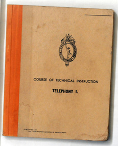
book, Australian Postmaster General's Dept, Course of Technical Instruction and Telegraphy, 1940's -1950's
The Postmaster-General's Department (P.M.G.) of Australia was created in 1901 with Federation taking control over all six Colonies (States) Postal and Telegraphic services within Australia to form the national Postal and Telegraphic services within Australia. The Department was administered by the Postmaster-General. This manual was produced as a syllabus of training for Army Personnel units in P.M.G's Department schools.In war times the postal organisation was a vital link between the services, the community and overseas centres. The Postmaster-General's Department co-operated with service departments in the installation and operation of radio, telephone and telegraph systems. Its laboratories also designed, developed and manufactured vital defence equipment. This item reflects that contribution and history.A 31 pp buff colored book with orange cloth binding. Black print on the front cover - a oval shaped logo with Post Office Communication Australia around a small sketch depicting Mercury, the messenger of the gods below an Australian coat-of-arms. Below that is the title,"COURSE OF TECHNICAL INSTRUCTION TELEPHONY 1".manual-telephony postmaster-general's-training-department instruction-book communications -
 Orbost & District Historical Society
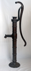
pump, late 19th -early 20th century
Hand operated water pumps were used to supply water prior to the widespread use of windmill pumps, electric pumps and city water systems. Usually an old pump was made from cast iron, wood or tin. Pumps were very important to people up through the 19th century as farm houses seldom had indoor plumbing with running water. These pumps were also used for outdoor irrigation or laundry purposes.Hand operated water pumps were important before indoor plumbing was adequate. An iron water pump - hand-operated by a lever to the side. A plunger moves up and down (missing). It has a spout and has been painted brown.pump-water irrigation rural -
 The Beechworth Burke Museum
Photograph
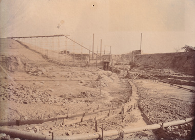
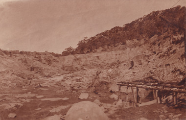
This photograph dating between the 1850s and early 1900s depicts an open cut sluicing site located in Allan's Flat looking upon the open cut from Staghorn Flat Number 1. Sluicing was undertaken in the area from 1850 to 1904. The image depicts a location mined by Yackandandah Sluicing Co. It portrays and open space with pipes laying on the ground and connected to pipes leaving the barge. These pipes were used to wash and seperate the qaurtz. There are two small buildings on high ground over looking the barge. Yackandandah Sluicing Co. was created by J.A. Wallace in the 1880s. The Yackandandah Sluicing Co. operated from the mid-1880s to the early 1900s, when resources eventually ran out. Open cut sluicing involved the use of high-powered hoses which used the centrifugal sand pump system (known as hydraulic sluicing) which broke down the soil which was then processed for quartz, gold and other materials. After the resources where drained, Wallace reaped the benefits of his mining business. Allan's Flat is located on the Yackandandah Creek, and is 10km north-east of Yackandandah and 20km south of Wodonga in Victoria's regional north-east. Allan's Flat was initially used to mine gold through alluvial methods, however that came to an end with little results. The mining business was then revived by J.A. Wallace with the introduction of hydraulic sluicing.The search for gold is ingrained into the history of Victoria and therefore, images like this one which portray an open cut sluicing site can reveal important information for society and technology for the date when the photograph was taken. This image is of important historical significance for its ability to convey information about sluicing and the methods used to find gold and other minerals in the lat 19th Century. It also shows a location where sluicing was undertook which provides insight into the impact of sluicing on the environment at a time when it was done. This image is important for current research into the history of Allan's Flat, a small regional location near Yackandandah in Victoria's North East. Therefore, this image has the capacity to be beneficial for research into society and the motivations of those living and working in this region during this period and therefore, has social significance. The Beechworth Burke Museum has additional images relating to gold sluicing and Allan's Flat which can be analysed and studied alongside images like this one.Sepia coloured retangular photograph printed on gloss photographic paper mounted on board.Revers: Sluicing at Allan's Fortallan's flat, north east gold, sluicing, gold sluicing, hydraulic sluicing, mining, gold and quartz mine, beechworth, burke museum, yackandandah -
 The Beechworth Burke Museum
Photograph, 1907-8
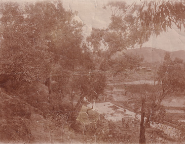
The photo from 1907-8 is a sepia print, depicting a small valley with building at base. There are flumes visible above areas of water, trees on hills and a few small cottages on the hillside. Cock's Pioneer Gold & Tin Sluicing Co NZ No 2 Site. The photo was taken of Matthews Gully looking west. Sluicing was undertaken in the area from 1900 to 1942 with some short breaks between these periods. The image depicts a location mined by Cocks Pioneer Gold and Tin Sluicing Company (as recorded on the annotation on the card mount) The Cocks Pioneer Gold and Tin Mines N.L was one of El Dorado's two largest open cut sluicing mines of the 20th Century. The other was named the Cocks El Dorado Gold Dredging Company. The Cocks Pioneer Mines operated from 1901 until 1941 and found a total of 117,378 ounces of Gold and 1,673 tones of tin concentrates over these years. The Cocks company was formed in 1898 and operated until 1941. Open cut sluicing involved the use of high-powered hoses which used the centrifugal sand pump system (known as hydraulic sluicing) which broke down the soil which was then processed for gold and other precious metals. From 1914 , four years after this image was captured, the company reformed to Cocks Pioneer Gold and Tin Mines NL (previously it was known as Cocks Pioneer Sluicing Co) and undertook large scale sluicing operations until 1929 and then 1934-1941. El Dorado is located on Reedy Creek and is surrounded by forested country to the north and east. It is 20 km east of Wangaratta in Victoria's regional north-east. John Cock was the son of a Cornish minor who arrived in El Dorado in 1858. Cock founded his gold and tin mining company which ran successfully for many years in the El Dorado region. It was an open cut sluicing company because of the abandonment of underground mining after this was deemed too dangerous. In 1935 Cock's El Dorado Company commissioned the floating dredge which is still visible in El Dorado today. The dredge was built by the Thompson engineering works, Castlemaine, and weighed over 2,000 tones and today has a place on the Victorian Registers of historic buildings. Interestingly, the name El Dorado does not derive from the gold in the region, but from the Barambogie pastoral run completed by William Baker in 1840-1841. Gold was discovered in El Dorado 1854 but the gold was too deep for individual prospectors to find, it required the use of heavy machinery.The search for gold is ingrained into the history of Victoria and therefore, images like this one which portray an open cut sluicing site can reveal important information for society and technology for the date when the photograph was taken. This image is of important historical significance for its ability to convey information about sluicing and the methods used to find gold in 1910. It also shows a location where sluicing was undertook which provides insight into the impact of sluicing on the environment at a time when it was done. This image is important for current research into the history of El Dorado, a small regional location near Wangaratta in Victoria's North East. Therefore, this image has the capacity to be beneficial for research into society and the motivations of those living and working in this region during this period and therefore, has social significance. The Beechworth Burke Museum has additional images relating to gold sluicing and El Dorado which can be analysed and studied alongside images like this one.Sepia coloured rectangle photograph printed on gloss photographic paper Reverse: 1997. 2613/ A02613/ No2 site/ Matthews Gully/ Cocks Pioneer G&T. ?? Co NZ/ No2 Site looking West/ 1907-8/ (7)sluicing, hydraulic sluicing, 1907, 1908, mining, cock's pioneer gold & tin sluicing co nz, nz, site no 2, matthews gully, west, valley, building, cottages, hillside, trees, water, gold and tin mine -
 The Beechworth Burke Museum
Photograph, 1910 - 1911
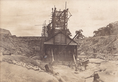
This photograph depicts Cock's Pioneer G & T Sluicing site No. 4 in El Dorado. Looking eastwards, the photo captures a wooden and tin building with various mining equipment strewn in the foreground. Underneath the verandah, figures can be seen. These are believed to be a Mr. Hollister (left), Mrs. Breustedt (4th from left), children Min and Chris Breustedt, and Kate Timmons holding a girl's hand. The Cocks Pioneer Gold and Tin Mines N.L was one of El Dorado's two largest open-cut sluicing mines of the 20th Century. The other was named the Cocks El Dorado Gold Dredging Company. The Cocks Pioneer Mines operated from 1901 until 1941 and found a total of 117,378 ounces of Gold and 1,673 tones of tin concentrates over these years. The Cocks company was formed in 1898 and operated until 1941. Open cut sluicing involved the use of high-powered hoses which used the centrifugal sand pump system (known as hydraulic sluicing) which broke down the soil which was then processed for gold and other precious metals. From 1914, four years after this image was captured, the company reformed to Cocks Pioneer Gold and Tin Mines NL (previously it was known as Cocks Pioneer Sluicing Co) and undertook large-scale sluicing operations until 1929 and then 1934-1941. The Cocks Pioneer was an extremely successful mining company during the 20th century. In the Annual Report of the Secretary for Mines for the year 1915, the Cocks Pioneer was the largest producer of gold and tin collecting 5,535 ozs. of gold and £7,500 of tin. Twenty years later in 1935, Cocks Pioneer was still one of the most profitable mines in Victoria, ranking as the second-highest dividend paying mine. The company produced a total of 3,650 kg of gold. El Dorado is located on Reedy Creek and is surrounded by forested country to the north and east. It is 20 km east of Wangaratta in Victoria's regional northeast. John Cock was the son of a Cornish miner who arrived in El Dorado in 1858. Cock founded his gold and tin mining company which ran successfully for many years in the El Dorado region. It was an open-cut sluicing company because of the abandonment of underground mining after this was deemed too dangerous. In 1935 Cock's El Dorado Company commissioned the floating dredge which is still visible in El Dorado today. The dredge was built by the Thompson engineering works, Castlemaine, and weighed over 2,000 tones and today has a place on the Victorian Registers of historic buildings. Interestingly, the name El Dorado does not derive from the gold in the region, but from the Barambogie pastoral run completed by William Baker in 1840-1841. Gold was discovered in El Dorado in 1854 but the gold was too deep for individual prospectors to find, it required the use of heavy machinery.The search for gold is ingrained into the history of Victoria and therefore, images like this one which portray an open cut sluicing site can reveal important information for society and technology for the date when the photograph was taken. This image is of important historical significance for its ability to convey information about sluicing and the methods used to find gold in 1910. It also shows a location where sluicing was undertook which provides insight into the impact of sluicing on the environment at a time when it was done. This image is important for current research into the history of El Dorado, a small regional location near Wangaratta in Victoria's North East. Therefore, this image has the capacity to be beneficial for research into society and the motivations of those living and working in this region during this period and therefore, has social significance. The Beechworth Burke Museum has additional images relating to gold sluicing and El Dorado which can be analysed and studied alongside images like this one.A black and white copy of a sepia coloured rectangular photograph printed on matte photographic paper mounted on boardObverse: COCKS PIONEER G + T SL CO, N.L. / 1910 - 11 / NO 4 SITE LOOKING EAST / 4 Reverse: 1997.2508 / AUG 29 1909cocks pioneer gold and tin sluicing company, el dorado, mining, sluicing, hydraulic mining, hollister, breustedt, timmons, gold, tin, gold rush, victoria -
 The Beechworth Burke Museum
Photograph, 1910
This photograph dating to 1910 depicts an open cut sluicing site located in El Dorado captured looking east up the open cut from the number 3 Barge site. Sluicing was undertaken in the area from 1900 to 1942 with some short breaks between these periods. The image depicts a location mined by Cocks Pioneer Gold and Tin Sluicing Company (as recorded on the annotation on the card mount). It portrays open cut rocks with a crevice in the center of the image where the sluicing was being undertaken. There is a small timber structure on the right of the image which could be an entrance to a mine or supports made of wood to prevent a cave in at the open cut site and above the cut rock there is bush. The timber structure has rail tracks on top of the bridge which could suggest the identification of this structure as a mine entrance. The rail tracks were used for little carts which hauled soil from the mine. The Cocks Pioneer Gold and Tin Mines N.L was one of El Dorado's two largest open cut sluicing mines of the 20th Century. The other was named the Cocks El Dorado Gold Dredging Company. The Cocks Pioneer Mines operated from 1901 until 1941 and found a total of 117,378 ounces of Gold and 1,673 tones of tin concentrates over these years. The Cocks company was formed in 1898 and operated until 1941. Open cut sluicing involved the use of high-powered hoses which used the centrifugal sand pump system (known as hydraulic sluicing) which broke down the soil which was then processed for gold and other precious metals. From 1914 , four years after this image was captured, the company reformed to Cocks Pioneer Gold and Tin Mines NL (previously it was known as Cocks Pioneer Sluicing Co) and undertook large scale sluicing operations until 1929 and then 1934-1941. El Dorado is located on Reedy Creek and is surrounded by forested country to the north and east. It is 20 km east of Wangaratta in Victoria's regional north-east. John Cock was the son of a Cornish minor who arrived in El Dorado in 1858. Cock founded his gold and tin mining company which ran successfully for many years in the El Dorado region. It was an open cut sluicing company because of the abandonment of underground mining after this was deemed too dangerous. In 1935 Cock's El Dorado Company commissioned the floating dredge which is still visible in El Dorado today. The dredge was built by the Thompson engineering works, Castlemaine, and weighed over 2,000 tones and today has a place on the Victorian Registers of historic buildings. Interestingly, the name El Dorado does not derive from the gold in the region, but from the Barambogie pastoral run completed by William Baker in 1840-1841. Gold was discovered in El Dorado 1854 but the gold was too deep for individual prospectors to find, it required the use of heavy machinery.The search for gold is ingrained into the history of Victoria and therefore, images like this one which portray an open cut sluicing site can reveal important information for society and technology for the date when the photograph was taken. This image is of important historical significance for its ability to convey information about sluicing and the methods used to find gold in 1910. It also shows a location where sluicing was undertook which provides insight into the impact of sluicing on the environment at a time when it was done. This image is important for current research into the history of El Dorado, a small regional location near Wangaratta in Victoria's North East. Therefore, this image has the capacity to be beneficial for research into society and the motivations of those living and working in this region during this period and therefore, has social significance. The Beechworth Burke Museum has additional images relating to gold sluicing and El Dorado which can be analysed and studied alongside images like this one.Sepia coloured rectangular photograph printed on gloss photographic paper mounted on board.Obverse: COCKS PIONEER Q + T SL CO, N.L. / 1910 / LOOKING EAST UP OPEN CUT / FROM NO3 BARGE SITE / Reverse: 1997 . 2611 / A02611el dorado, north east gold, sluicing, gold sluicing, hydraulic sluicing, 1910, gold and tin mine, open cut mining, mining, gold mining, north-east victoria, beechworth, burke museum -
 The Beechworth Burke Museum
Photograph, c.2000
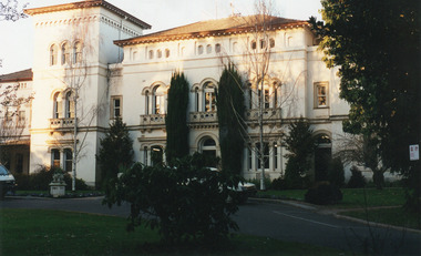
This photograph was captured on an undisclosed date and by an unidentified photographer. It was printed in colour through the company AGFA which is a Belgian-German Multinational Corporation. This business prints, develops, manufactures and distributes digital imaging products, software and systems. It was founded in 1967 and continues to operate today. Beechworth's Mayday Hills was chosen as the site of Victoria's newest asylum, at the time, due to the landscape and altitude. The hilltop atmosphere and the native fauna, it was argued, would assist in the cure of the patients kept at the hospital (Wood 1985, 122). The positioning of the hospital had a beneficial effect on the rural town. A pamphlet published by James Ingram and Son (1849) reveal that famous landmarks in Beechworth which included the Post Office, Gaol, Courthouse and Asylum "demonstrate the appreciation of Beechworth by the Government not only as as important district center, but also as a site unrivaled as a sanitarium". There were other locations in contention at the time, but ultimately Beechworth was chosen (Craig 2000, 33). Prior to the creation of the Asylum in Beechworth, those charged with having mental illnesses or, as it was termed, "insanity" were unable to be properly cared for in the Gaol (which is where they were often sent). John Buckley Castieau wrote, in 1861 for the Ovens and Murray Advertiser, that the Gaol was unable to properly care for those classified then as "insane" but that they would endeavor to treat them above the other inmates (which he notes is not always the case in other establishments). Castieau wrote this in favour of supporting the building of the Mayday Hills Hospital in Beechworth. It was stated that at the time the Mayday Hills Hospital was built, there were 83 prisoners kept in the Gaol who were to be rehoused to the Hospital on the grounds of "insanity". The classification as someone as "insane", in this period of time is a reflection on the inability to cure and understand illnesses of the mind during the mid to late 1800s. Opening on the 24th of October 1867, the Mayday Hills Hospital was originally named the "Ovens Lunatic Asylum", a title which is very much a product of its time. Whilst controversial, changes to the name is part of the history of the Hospital and can provide much insight into the understanding of mental illness throughout history and the use/disuse of this term provides information into the reception/changing opinions of mental illness in society. The Hospital would later become known as the "Mayday Hills Asylum" and/or "Mayday Hills Hospital" with the latter being the most commonly used title. An article in the Ovens and Murray Advertiser notes that on the 7th of March 1865, the foundation stone of the Hospital was laid (it would officially open in 1867) and that it was such a moment of accomplishment and joy for Beechworth that a letter to the editor even suggested that there should be a holiday dedicated to the day the foundation stone as laid. This reveals an extent to which the townspeople of early Beechworth valued the construction of the Hospital in their town. It provided the town with a sense of prestige and honour.At first glance, the remains of the Mayday Hills Hospital in Beechworth, Victoria, inspire tragedy, trauma and beauty. The buildings themselves, with their Italianate style Renaissance architecture designed by J.J. Clark (Craig 2000, 49 & Smith 2016, 203) reflect a bygone period of European and Australian history. The gardens provide a sense of tranquility and beauty. The experience of those within these walls remains a valuable area of study to provide a more complete understanding. This particular hospital is considered the fourth of its like and one of three identified as the largest of their kind. The Mayday Hills Hospital is a sister to the Kew and Ararat Asylums in Melbourne which are both located in relative proximity. Understanding the role of the Mayday Hills Hospital in Beechworth history is integral to understanding the development of the goldfields town, but also for providing important information as to the history of caring for, and the reception of, mental illnesses in Australian and wider European history. Mayday Hills provides a case study which can be researched through oral history, an analysis of the grounds/buildings and through images like this postcard which portray the structure in a highly deliberate manner. Images like this depict the strong façade of the Hospital and provide a glimpse into the tranquility of the gardens. This has been done deliberately to provide a sense of comfort and healing about the building to those looking from the outside. Further research into the importance of the Hospital in Beechworth and it's connection to the town will be supported through images like these kept in the Mayday Hills photo album in the collection of the Burke Museum.Coloured rectangular photograph printed on gloss photographic paper.Reverse: AGFAbeechworth, mayday hills, mayday hills asylum, mental health, history of mental health, asylum, 1860s, gold town, north-east victoria, kew asylum, ararat asylum -
 Flagstaff Hill Maritime Museum and Village
Domestic object - Iron
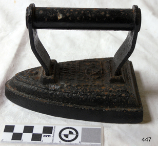
Before the introduction of electricity, irons were heated by combustion, either in a fire or with some internal arrangement. An "electric flatiron" was invented by American Henry Seely White and patented on June 6, 1882. It weighed almost 15 pounds (6.8 kg) and took a long time to heat. The UK Electricity Association is reported to have said that an electric iron with a carbon arc appeared in France in 1880, but this is considered doubtful. Two of the oldest sorts of iron were either containers filled with a burning substance, or solid lumps of metal which could be heated directly. Metal pans filled with hot coals were used for smoothing fabrics in China in the 1st century BC. A later design consisted of an iron box which could be filled with hot coals, which had to be periodically aerated by attaching a bellows. In the late nineteenth and early twentieth centuries, there were many irons in use that were heated by fuels such as kerosene, ethanol, whale oil, natural gas, carbide gas (acetylene, as with carbide lamps), or even gasoline. Some houses were equipped with a system of pipes for distributing natural gas or carbide gas to different rooms in order to operate appliances such as irons, in addition to lights. Despite the risk of fire, liquid-fuel irons were sold in U.S. rural areas up through World War II. In Kerala in India, burning coconut shells were used instead of charcoal, as they have a similar heating capacity. This method is still in use as a backup device, since power outages are frequent. Other box irons had heated metal inserts instead of hot coals. From the 17th century, sadirons or sad irons (from Middle English "sad", meaning "solid", used in English through the 1800s[4]) began to be used. They were thick slabs of cast iron, triangular and with a handle, heated in a fire or on a stove. These were also called flat irons. A laundry worker would employ a cluster of solid irons that were heated from a single source: As the iron currently in use cooled down, it could be quickly replaced by a hot one. https://en.wikipedia.org/wiki/Clothes_ironThis iron is typical of the clothes iron used before electric irons superseded it.Salter iron no. 6, painted black but with rust showing through. Salter iron no. 6.flagstaff hill, warrnambool, shipwrecked-coast, flagstaff-hill, flagstaff-hill-maritime-museum, maritime-museum, shipwreck-coast, flagstaff-hill-maritime-village, iron, clothes, laundry -
 Flagstaff Hill Maritime Museum and Village
Clocks, 1939-1946
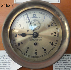
Chelsea Clock Company History: The Chelsea Clock Company is an American clock manufacturing company that started before 1880 with Joseph Henry Eastman who founded the Harvard Clock Company and produced 800 clocks of marine, carriage, shelf and banjo types. He went on to change the company name to the Boston Clock Company in 1884. After several name changes in 1897, the Chelsea Clock Company was finally founded. Clocks produced by Chelsea Clock Company have been found in the White House, on US Naval Ships, and in homes and offices around the world. After the company first began life as the Harvard Clock Company, it was named the Boston Clock Company, the Eastman Clock Company before finally becoming the Chelsea Clock Company in July of 1897. The company had developed many patents and innervations over these years and between 1939 and 1946 during World War II they were awarded contracts by the U.S Maritime Commission and produced vast numbers of clocks for both merchant and naval ships. U.S Maritime Commission History: The United States Maritime Commission (MARCOM) was an independent executive agency of the U.S. federal government that was created by the Merchant Marine Act of 1936, and replaced the United States Shipping Board which had existed since World War I. It was intended to formulate a merchant shipbuilding program to design and build five hundred modern merchant cargo ships to replace the World War I vintage vessels that comprised the bulk of the United States Merchant Marine, and to administer a subsidy system authorized by the Act to offset the cost differential between building in the U.S. and operating ships under the American flag. It also formed the United States Maritime Service for the training of seagoing ship's officers to man the new fleet. The purpose of the Maritime Commission was to formulate a merchant shipbuilding program to design and then have built over a ten-year period 900 modern fast merchant cargo ships which would replace the World War I-vintage vessels Those ships were intended to be then leased to U.S. shipping companies for their use in the foreign seagoing trades the aim was to offer better and more economical freight services. The ships were also intended to serve as a reserve naval auxiliary force in the event of armed conflict which was a duty the U.S. merchant fleet had often filled throughout the years since the Revolutionary War. From 1939 through the end of World War II, the Maritime Commission funded and administered the largest and most successful merchant shipbuilding effort in world history, producing ships for both navy and merchant marine. By the end of the war, U.S. shipyards working under Maritime Commission contracts had built a total of 5,777 ocean-going merchant and naval ships. In early 1942 both the training and licensing was transferred to the U.S. Coast Guard for administration, then later to the Maritime Service final responsibility was conveyed to the newly created War Shipping Administration which was created to oversee the operation of merchant ships being built by the Emergency Program to meet the needs of the U.S. Armed Services. With the end of World War II, both the Emergency and Long Range shipbuilding programs were terminated as there were far too many merchant vessels now for the Nation's peacetime needs. In 1946, the Merchant Ship Sales Act was passed to sell off a large portion of the ships built during the war to commercial buyers, both domestic and foreign. The U.S Maritime Commission was officially disbanded on May 24th 1950. These clocks were to be found on all ships made in American for the war effort between 1939 and 1946. They are a significant reminder of the sacrifice by those who served in the merchant marine and the navy’s during the Second World War. The item is a part of our social history that reminds us of these dark times. The loses of family members, along with the trauma that many sailors had endured and had to live with for the rest of their lives once they were released from service and allowed to go home.American Clock is an 8-day marine clock made by the Chelsea clock Co for the “US Maritime Commission” . There is a second smaller dial for the seconds and 24-hour markings. Also a fast-slow adjuster to the top of the dial. The clock is an 8 day marine clock with US Maritime Commission inscribed on face in black lettering. flagstaff hill, warrnambool, shipwrecked-coast, flagstaff-hill, flagstaff-hill-maritime-museum, maritime-museum, shipwreck-coast, flagstaff-hill-maritime-village, clock, us maritime commission, chelsea clock company, horology, maratime clock -
 Bendigo Military Museum
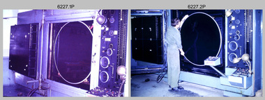
Photograph - Photographic Technicians operating the KLIMSCH Camera at the Army Survey Regiment, Fortuna, Bendigo, c1988
These nine photographs were most likely taken in c1988 in Lithographic Squadron at the Army Survey Regiment, Fortuna, Bendigo. The equipment operated by the technicians is the KLIMCH camera. The main tasks undertaken by the technicians were most likely enlargements and reductions of map reproduction material. The KLIMSCH Commodore camera was introduced in 1953 and was the largest in the Southern Hemisphere. It was replaced with a new model of the same size in 1979. The new model with its computer-based interface provided productivity gains with improved speed and its consistent results led to less wastage in time and materials. Its variomat lens system provided improved retention of map feature linear weights during the camera reduction process. The camera which was specially made for the Army in Germany was fully automatic and power operated. It was claimed to be one of the biggest automatic cameras of its type in the world. It was made to the specifications of the Royal Australian Army Survey Corps to assist in the production of the very high standard maps for the Army. There are several more photos catalogued in the Victorian Collections database of RA Svy personnel operating the KLIMSCH camera.This is a set of four photographs of technicians operating the KLIMSCH Camera at the Army Headquarters Survey Regiment, Bendigo c1988. The photographs are on 35mm colour slides scanned at 96 dpi. They are part of the Army Survey Regiment’s Collection. .1) - Photo, colour, c1988, KLIMSCH Camera. .2) - Photo, colour, c1988, KLIMSCH Camera, unidentified technician. .3) - Photo, colour, c1988, KLIMSCH Camera. .4) - Photo, colour, c1988, KLIMSCH Camera, L to R: SPR Shona Hastie, CPL Paul Baker. .5) - Photo, colour, c1988, KLIMSCH Camera. .6) & .7) - Photo, colour, c1988, KLIMSCH Camera, SPR Shona Hastie. .8) & .9) - Photo, colour, c1988, KLIMSCH Camera, SPR Russell Pajank.35mm colour slides are in good condition.rasvy, royal australian survey corps, army survey regiment, army svy regt, fortuna, asr, litho sqn -
 Bendigo Military Museum
Photograph - Photogrammetric Equipment – Army Survey Regiment, Bendigo and School of Military Survey Bonegilla, c1960s to c1980s
This is a set of 14 photographs of RA Svy technicians operating photogrammetric equipment in Air Survey Squadron, Army Survey Regiment, Fortuna, Bendigo; and the School of Military Survey Bonegilla c1960s to c1980s. The Wild B9 stereo plotter were introduced in 1962 and the Wild B8 stereo plotter was introduced in 1966. The Wild B9 and B8 stereo plotters were used for plotting topographic detail and contours. These analogue machines were manually controlled by adjusting the control knobs for the orientation of the 3D image. The B9s used a four and a half square, and the B8s used a nine-inch square photo image on a film or glass diapositive which allowed highly accurate extraction of map features. At first, plotting with B8 and B9 stereo plotters was undertaken at the aerial photography scale of 1:80,000 in pencil onto a controlled plotting sheet. Sheets were then inked up and reduced photographically to the 1: 100,000 publication scale for scribe impression production. In the early days topographic detail and contours were plotted with a pencil or ink pen mounted at the far end of the pantograph arm. The plotting procedure was upgraded to direct plotting in ink with photographic reduction to publication scale. In 1975 four B8s were upgraded with tri-axis locaters as part of the Input Sub-system to enable digital extraction to AUTOMAP 1’s topographic database. When AUTOMAP 2 was introduced in 1982 these B8s were upgraded, and additional machines added to expand the Army Survey Regiment’s digital capture capability. There are several more photos catalogued in the Victorian Collections database of RA Svy personnel operating Wild B9 and B8 stereo plotters.Photogrammetric Equipment – Army Survey Regiment, Fortuna, Bendigo c.1981. . .7) – Unidentified technician operating Wild B8 stereo plotter in AUTOMAP 1 at ASR. .8) - Wild B8 stereo plotter in AUTOMAP 1 at ASR. Photogrammetric Equipment – Army Survey Regiment, Fortuna, Bendigo. c1981. .9) – ASR’s CPL Dave Cook in AUTOMAP 1 operating a Wild B8 stereo plotter. This is a set of 14 photographs of RA Svy technicians operating photogrammetric equipment at the Army Survey Regiment (ASR), Bendigo and the School of Military Survey (SMS) Bonegilla. c1960s to c1980s. The photographs are on 35mm colour slides and were scanned at 96 dpi. .1) - Photo, colour, c1964. Unidentified ASR technicians operating analogue Wild B9 stereo plotters. .2) - Photo, colour, c1974. ASR’s SPR Mick Minchin operating an analogue Wild B8 stereo plotter. .3) to .6) - Photo, colour, c1980. Photogrammetry Instructor SGT Neil ‘Ned’ Kelly at the SMS operating an analogue Wild B8 stereo plotter. .7) - Photo, colour, c1981. Unidentified technician operating Wild B8 stereo plotter in AUTOMAP 1 at ASR. .8) - Photo, colour, c1981. Wild B8 stereo plotter in AUTOMAP 1 at ASR. .9) to .14) - Photo, colour, c1981. ASR’s CPL Dave Cook in AUTOMAP 1 operating a Wild B8 stereo plotter..1P to .14P - Some of the equipment is annotated on the frame of the 35mm slides.royal australian survey corps, rasvy, army survey regiment, army svy regt, fortuna, asr, photogrammetry -
 Bendigo Military Museum
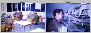
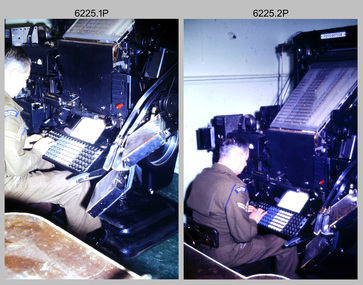
Photograph - Typesetting Equipment and Personnel, Army Survey Regiment, Fortuna, Bendigo, c1968 to 1979
This is a set of nine photographs of cartographic typesetting equipment and personnel in Cartographic Squadron at the Army Survey Regiment, Fortuna, Bendigo circa 1968 to 1979. The rooms on the top floor of Fortuna Villa where the photos were taken were formally the nursery and boys bedrooms during the Lansell family’s occupation of the building. The Fotosetter type setting machine replaced the letterpress method of type production in 1956. Its operator entered the text using a type order provided by cartographic draughtsmen/ draughtswomen. The type was output on a film positive, which was contacted onto strip film. The text was cut out by cartographic draughtsmen/ draughtswomen and affixed onto type sheets using bees wax. Cartographic Squadron’s CPL Arty Lane specialised in the operation of the Fotosetter type setting machine for many years, as shown in photos .3P and .4P. For more information on the Fotosetter, see page 71 of Valerie Lovejoy’s book 'Mapmakers of Fortuna – A history of the Army Survey Regiment’ ISBN: 0-646-42120-4. The computer based Editwriter Model 7500 typesetting system was introduced in 1975 as a replacement to the aging Fotosetter. It was operated by a specialised technician, who generated a large variety of map type styles and sizes quickly and reliably, as well as text panels. Output on Copy proof adhesive backed stripping type film replaced messy wax and spray adhesives in 1978. The Editwriter capability supported all RASvy units and its contractor type setting requirements. SGT Jim McDonald operated the Editwriter for a couple of years in the late 1970’s. He is seen in photos .7P and .8P. reading off a type order and entering text into the computer. See item 6181.23P, photo .1P for a reduced scale photo of SGT Jim McDonald undertaking this task. Also see item 6123.12P photos .1P and .2P featuring CPL Paul Richards, who was another technician that operated the Editwriter for several years in the 1980s. The Editwriter was also operated by SSGT Pat Lumsden, as featured in photo .9P taken in 1979. The Monotype Photolettering Machine seen in photos .5P and .6P is understood to be in service for a shorter period, as it was not as productive compared to the Fotosetter and Editwriter. This is a set of nine photographs of cartographic typesetting equipment at the Army Survey Regiment, Fortuna, Bendigo, c1968 to c1979. Black and white photos are on photographic paper and scanned at 300 dpi. .1) - Photo, black & white, c1960s, Fotosetter type setting machine, unidentified technician. .2) - Photo, black & white, c1960s, Fotosetter type setting machine. .3) to .4) - Photo, black & white, c1968, Fotosetter type setting machine, CPL Arty Lane. .5) to .6) - Photo, black & white, c1970s, Monotype Photolettering Machine, unidentified technician. .7) to .8) - Photo, black & white, c1979, Typesetting machine, ‘Editwriter’ Model 7500, SGT Jim McDonald. .9) - Photo, black & white, 1979, Typesetting machine, ‘Editwriter’ Model 7500, SSGT Pat Lumsden.Personnel and equipment are identified in photos .1P to .3P. on a card. A description is provided: ‘Fotosetter: This model was used from 1956 to 1974. Where photograph was taken: Army Survey Regiment. Person in Photograph: Arty Lane. Approx date photograph taken: 1968. Any Misc Information: All type on maps was set on this machine. The operator of the machine (Ex SGT Lane) joined the Army in 1956 and was discharged in 1977. Also with Survey from 1942 to 1946. Information given by: Arty Lane’. Photo .9P is dated 1979 on the back.’royal australian survey corps, rasvy, army survey regiment, army svy regt, fortuna, asr, carto -
 Bendigo Military Museum
Photograph - Photogrammetric Equipment – Army Survey Regiment, Fortuna, Bendigo, c1960s to c1980s
This is a set of eight photographs of technicians operating photogrammetric equipment in Air Survey Squadron, Army Survey Regiment, Fortuna, Bendigo. c1960s to c1980s. The Wild A9 Stereocomparator and Wild B9 stereo plotter were introduced in 1962. The Wild B8 stereo plotter was introduced in 1966. Technicians used the Wild A9 Stereocomparator to accurately measure between pass, tie, and survey control points on aerial photographs. The Wild B9 and B8s were used for plotting topographic detail and contours. These analogue machines were manually controlled by adjusting the control knobs for the orientation of the 3D image. The B9s used a four and a half square, and the B8s used a nine-inch square photo image on a film or glass diapositive which allowed highly accurate extraction of map features. At first, plotting with B8 and B9 stereo plotters was undertaken at the aerial photography scale of 1:80,000 in pencil onto a controlled plotting sheet. Sheets were then inked up and reduced photographically to the 1: 100,000 publication scale for scribe impression production. In the early days topographic detail and contours were plotted with a pencil or ink pen mounted at the far end of the pantograph arm. The plotting procedure was upgraded to direct plotting in ink with photographic reduction to publication scale. In 1975 four B8s were upgraded with tri-axis locaters as part of the Input Sub-system to enable digital extraction to AUTOMAP 1’s topographic database. When AUTOMAP 2 was introduced in 1982 these B8s were upgraded, and additional machines added to expand the Army Survey Regiment’s digital capture capability. This is a set of eight photographs of technicians operating photogrammetric equipment in Air Survey Squadron, Army Survey Regiment, Fortuna, Bendigo. c1960s to c1980s. Black and white and colour photos are on photographic paper and scanned at 300 dpi. .1) - Photo, black & white, c1965. Unidentified technician operating a Wild A9 Stereocomparator. .2) - Photo, black & white, c1965. Unidentified technician operating a Wild B9 stereo plotter. .3) - Photo, black & white, c1967. L to R: Unidentified technician, SPR Ken Jeffery operating a Wild B9 stereo plotter. .4) - Photo, colour, c1974. Unidentified technician, operating a Wild B8 stereo plotter. .5) - Photo, black & white, c1974. Unidentified technician operating a Wild B8 stereo plotter. .6) to .7) - Photo, black & white, c1979. Unidentified technicians operating a Wild B8 stereo plotter. .8) - Photo, black & white, c1985. Unidentified technician in AUTOMAP 2 operating a Wild B8 stereo plotter..1P, .2P, .4P, .5P, .7P – no annotations. .3P – annotated ‘Standing - , Seated SPR Ken Jefferies (sic). .6P – annotated with date ‘1979’ .8P – annotated ‘AUTOMAP 2’royal australian survey corps, rasvy, army survey regiment, army svy regt, fortuna, asr, air survey, photogrammetry -
 Bendigo Military Museum
Photograph - Johnson Ground Elevation Meter (JGEM) Survey Vehicle - Army Survey Regiment, Fortuna, Bendigo, c1960s
This is a set of 16 photograph of the Royal Australian Survey Corps’ Johnson Ground Elevation Meter (JGEM) Survey Vehicle taken at the Army Survey Regiment, Fortuna, Bendigo. The JGEM vehicle was extensively used by RA Svy within Australia from the late 1960s. A limited number of Ground Elevation Meter (GEM) station wagon type vehicles were manufactured by General Motors Corporation (GMC) in the USA for the United States Geological Survey, Canada’s mapping agencies, RA Svy and National Mapping (Natmap). The GEM was a four-wheel drive, four-wheel steer vehicle. Four-wheel steering was necessary to avoid systematic errors caused by non-tracking of front and rear wheels on conventionally steered vehicles. The manufacturer substituted the rear axle with a front axle and connected them to form the four-wheel steering mechanism. The two Australian GEM vehicles, referred to as Johnson GEMs (JGEMs) were converted into right-hand drive. After delivery in 1964, acceptance Natmap and RA Svy testing and operator training was undertaken at the Army's School of Military Survey located at Balcombe, Victoria. A small fifth wheel was mounted on a cantilever arm suspension midway between the front and rear wheels on the right side of the vehicle. It was lowered to and raised from its operating position by use of a constant pressure air cylinder. A telescopic bar, suspended between the front and rear axles, provided the reference datum for the angle measurement. The wheel provided the velocity or distance signal through a pulse generator system. A sensitive pendulum mounted on this bar provided the angle measurement for each minute distance traversed. The JGEM contained electromechanical instruments used to determine relative elevations, by trigonometric principles, along a traversed path. These relative elevations were obtained through apparatus which measures the instantaneous angle of inclination of the road and the instantaneous velocity of the meter along such a path. Road routes over which the JGEM operated were planned so that each started and ended as near as practicable to an existing point of known elevation (formally referred to as a level traverse bench mark). The difference in height from the bench mark and the road surface alongside the JGEM’s fifth wheel was measured with a level and staff. Along each route, mapping control photo reference points where new elevation values were required were identified on aerial photographs. Under favourable conditions it was possible to survey as much as 160km in an ordinary working day. The first of RA Svy’s JGEM operations was undertaken in 1:250,000 scale map areas of Queensland. CPL John Hook was the JGEM’s main operator in the early 1970s undertaking operations covering 1:250,000 scale map blocks over northern Victoria and central NSW, each requiring 36 points (9 runs of photography and 4 points across. SPR Lyn Thompson and SPR Bob McDonagh teamed with CPL Hook on some of these JGEM operations. When RA Svy was integrated into the Royal Australian Engineers in 1996, the JGEM vehicle with the Survey Corps collection was donated to its museum. It is believed to be the last of the original manufactured fleet in existence. The JGEM has undergone extensive refurbishment to achieve roadworthiness and is currently housed at The Australian Army Museum of Military Engineering, Hoslworthy Barracks, NSW. It can be viewed by making an appointment with the museum’s curator.This is a set of 16 photograph of the Royal Australian Survey Corps’ Johnson Ground Elevation Meter (JGEM) Survey Vehicle taken at the Army Survey Regiment, Fortuna, Bendigo. The photographs were on 35mm slide film and were scanned at 96 dpi. They are part of the Army Survey Regiment’s Collection. .1) - Photo, colour, c1960s, Johnson Ground Elevation Meter (JGEM) Survey Vehicle .2) - Photo, colour, c1960s, JGEM instrumentation, on-board computer. .3) - Photo, colour, c1960s, JGEM instrumentation. .4) - Photo, colour, c1960s, JGEM instrumentation, on-board computer. .5) - Photo, colour, c1960s, JGEM tyre pressure controller .6) - Photo, colour, c1960s, JGEM rear doors, SGT Geoff Briggs. .7) - Photo, colour, c1960s, JGEM 5th wheel distance/angle measurement device in lowered position, SGT Geoff Briggs. .8) - Photo, colour, c1960s, JGEM 5th wheel distance/angle measurement device in lowered position. .9) & .10) - Photo, colour, c1960s, JGEM tyre pressure system, SGT Geoff Briggs. .11) - Photo, colour, c1960s, JGEM tyre pressure system. SGT Geoff Briggs. .12) - Photo, colour, c1960s, JGEM levelling scope, levelling staff, unidentified technicians. .13) & .14) - Photo, colour, c1960s, JGEM levelling scope, unidentified technician. .15) & .16) - Photo, colour, c1960s, probably survey operation adjusted height plotted on block base sheet. .1P to .16P - Some of the equipment is annotated on the frame of the 35mm slides.royal australian survey corps, rasvy, army survey regiment, army svy regt, fortuna, asr, surveying -
 Bendigo Military Museum
Photograph - Cartographic Production – Army Survey Regiment, Fortuna, Bendigo, c1960 -1975
This is a set of 10 photographs of Cartographic Squadron technicians undertaking map production tasks in at the Army Survey Regiment, Fortuna, Bendigo circa 1968 to 1975. Production was undertaken on the top floor of Fortuna Villa. The Fotosetter type setting machine shown in photos .1P and .2P. replaced the letterpress method of type production in 1956. CPL Arty Lane specialised in the operation of the Fotosetter type setting machine for many years. For more information on the Fotosetter, see page 71 of Valerie Lovejoy’s book 'Mapmakers of Fortuna – A history of the Army Survey Regiment’ ISBN: 0-646-42120-4. The computer based Editwriter Model 7500 typesetting system shown in photos .3P and .4P. was introduced in 1975 as a replacement to the aging Fotosetter. It was operated by a specialised technician, who generated a large variety of map type styles and sizes quickly and reliably, as well as text panels. Output on Copy proof adhesive backed stripping type film replaced messy wax and spray adhesives in 1978. The Editwriter capability supported all RASvy units and its contractor type setting requirements. The Aristo Co-ordinatorgraph shown in photos .5P to .7P was introduced in 1962. It was a large heavy steel framed light table with a scribing head that moved in a XY direction using a vernier calibrated measuring scale to 0.001 of an inch. Whilst hand operated it was much quicker and accurate than manual grid and graticule calculation, plotting and scribing. The history of co-ordinatorgraphs is covered in more detail with additional historic photographs, in pages 50 to 51 and page 88 of Valerie Lovejoy’s book 'Mapmakers of Fortuna – A history of the Army Survey Regiment’ ISBN: 0-646-42120-4. The scribing process as shown in photos .8P to .9P was the cartographic process of drafting features such as drainage, relief, vegetation, roads and culture on specially coated map reproduction material. The cartographic technician scribed out the map feature such as a contour to a specified line width on the map sheet, using a tool affixed with a sapphire tipped cutter. The quality control edit (Proving) stage of map production shown in photo .10P was the first opportunity to independently and systematically inspect a proof of the map.This is a set of 10 photographs of cartographic Squadron technicians undertaking map production tasks at the Army Survey Regiment, Fortuna, Bendigo, c1968 to c1975. The photographs were on 35mm colour slides and scanned at 96 dpi. They are part of the Army Survey Regiment’s Collection. .1) to .2) - Photo, colour, c1968, Fotosetter type setting machine, CPL Arty Lane. .3) to .4) - Photo, colour, c1975, Typesetting machine, ‘Editwriter’ Model 7500. .5) - Photo, colour, c1960s, PTE Desi Asaris and CPL Kalen Sargent operating Aristo Co-ordinatorgraph equipment. .6) - Photo, colour, c1970s, L to R: CPL Desi Asaris, CPL John Bennett, operating Aristo Co-ordinatorgraph equipment. .7) - Photo, colour, c1970s, L to R: CPL John Bennett, CPL Desi Asaris operating Aristo Co-ordinatorgraph equipment. .8) - Photo, colour, c1970s, L to R: CPL Desi Asaris scribing drainage, CPL John Bennett. .9) - Photo, colour, c1970s, CPL Desi Asaris scribing drainage. .10) - Photo, colour, c1970s, L to R: CPL Desi Asaris, CPL John Bennett and their supervisor WO2 Roger Rix inspecting features on an aeronautical chart proof. .1P to .10P There are no annotations stored with the 35mm slides.royal australian survey corps, rasvy, army survey regiment, army svy regt, fortuna, asr, carto