Showing 628 items matching "push"
-
 Orbost & District Historical Society
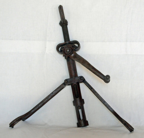
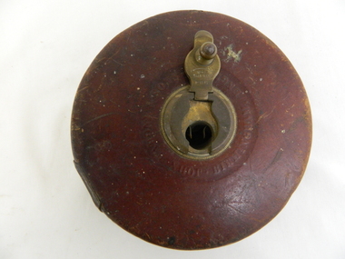
car wheel rim splitter, 1920's
... After the tire was repaired or a new one was ready to be put on the collapsed rim the tool was used to push the rim back together and the safety key could be reinserted....After the tire was repaired or a new one was ready to be put on the collapsed rim the tool was used to push the rim back together and the safety key could be reinserted. ...A rim splitter was used on the outer rims of older vehicles to facilitate removal and replacement of tires. The tool was used to remove a tyre and replace it onto a split wheel rim. After the air was let out, the safety rim key was pulled. The swing arms were spread out and the three arms evenly spaced around the rim. The single arm with the screw gear needed to be close to the split so that the hooks fit on the rim and the rim was then pulled inward and the tyre could be be removed from the rim. After the tire was repaired or a new one was ready to be put on the collapsed rim the tool was used to push the rim back together and the safety key could be reinserted. A rim splitter were a universal type tool used for many cars of the 1920's and 1930's.A cast iron rim splitter which has two hinged side arms with hooked ends. The middle shaft has a hooked end and an inner bolt that can be screwed up or down.St Joseph Michigan Hercules Product Co Made in U.S.A. L 7motoring rim-splitter tyres tool -
 Orbost & District Historical Society
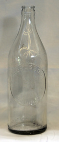
bottle, D. Drossou, 1930's
... The inside was cleaned by pushing the bottle onto a revolving brush. The reusing of the bottles went on until the bottle was broken or the top became chipped. ...The inside was cleaned by pushing the bottle onto a revolving brush. The reusing of the bottles went on until the bottle was broken or the top became chipped. ...Dross Drossou sold his cordial manufacturing business to Phillips and Stone, a Bairnsdale company, in 1948. Phillips and Stone continued to manufacture soft drinks at Orbost until the early 1970's when the factory became a distribution centre. It closed as a distribution centre in 1978 and later served as the headquarters of the Orbost State Emergency Service. The site of the Cordial Factory now forms part of a carpark. A deposit on the bottles was added to all sales as they left the factory. The returned bottles were washed and the old label removed. The inside was cleaned by pushing the bottle onto a revolving brush. The reusing of the bottles went on until the bottle was broken or the top became chipped. This bottle is an example of a product manufacture by a local industry no longer existing.A clear glass cylindrical bottle with a tapered neck.D. DROSSOU ORBOSTbottle drossou orbost-cordial-factory food beverages -
 Federation University Historical Collection
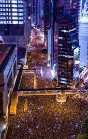
Photograph - Colour Photograph, Street Protests in Hong Kong against proposed extradition laws, 2019, 17/06/2019
... The police tactics to break up the demonstrations on June 12, including the use of more than 150 tear gas canisters to push protesters far away from the government office, created a new set of demands from the protesters. ...A day after Lam suspended her push for the bill, expecting it to defuse a crisis that has seen violent clashes between mostly young protesters and police, the centre of Hong Kong was brought to a complete standstill as the masses marched to chastise her for refusing to withdraw the bill or apologise when first asked to, and declaring that nothing short of her resignation would satisfy them now. ...The police tactics to break up the demonstrations on June 12, including the use of more than 150 tear gas canisters to push protesters far away from the government office, created a new set of demands from the protesters. ...Carrie Lam, Hong Kong’s chief executive, had plenty of political support in the territory’s pro-Beijing legislature to pass a bill that would allow extraditions to mainland China. The legislators were set to begin discussing the bill in early June, and intended to vote on it just weeks later. A series of protests took place, and after a June 16 protest saw the largest turnout yet, Ms. Lam made a major concession: She postponed the bill, at least temporarily. It was an undeniable victory for the protesters — but it did little to quell the unrest. Since the bill could later be reintroduced, protesters felt they remained in danger. The police tactics to break up the demonstrations on June 12, including the use of more than 150 tear gas canisters to push protesters far away from the government office, created a new set of demands from the protesters. Now, instead of just calling for the withdrawal of the bill and Ms. Lam’s resignation, they said they wouldn’t be content unless there was an independent investigation of officers’ conduct. They also wanted the release of protesters arrested on June 12, and for the government to rescind its description of the demonstrations as a “riot,” a designation that carries legal significance. None of that has happened. Many analysts say Ms. Lam is unlikely to step down, nor would Beijing accept her resignation if she offered it. She has more wiggle room on the other demands, but has not indicated any willingness to budge. The Hong Kong Protests are a leaderless, digital movement.There is no single leader or group deciding on or steering the strategy, tactics and goals of the movement. Instead, protesters have used forums and messaging apps to decide next steps. Anyone can suggest a course of action, and others then vote on whether they support it. The most popular ideas rise to the top, and then people rally to make them happen. At its best, this structure has empowered many people to participate and have their voices heard. Protesters say it keeps them all safe by not allowing the government to target specific leaders. Their success in halting the extradition bill, which was shelved by the territory’s chief executive, speaks to the movement’s power. Despite the lack of a clear leader, protesters have shown extensive coordination at the demonstrations, having planned the specifics online beforehand. Supply stations are set up to distribute water, snacks, gloves, umbrellas and shields made of cardboard. Volunteer first aid workers wear brightly colored vests. People form assembly lines to pass supplies across long distances, with protesters communicating what they need through a series of predetermined hand signals. Anyone walking in dangerous areas without a helmet or a mask is quickly offered one. No individual can speak on behalf of the protesters, which makes negotiations difficult, if not impossible. (https://www.nytimes.com/2019/07/02/world/asia/hong-kong-protest-explained.html, accessed 07/07/2019) Hong Kong’s amended extradition law would allow the extradition of suspects to mainland China for the first time. Supporters say the amendments are key to ensuring the city does not become a criminal refuge, but critics worry Beijing will use the law to extradite political opponents and others to China where their legal protections cannot be guaranteed. The government claims the push to change the law, which would also apply to Taiwan and Macau, stems from the killing last year of a Hong Kong woman while she was in Taiwan with her boyfriend. Authorities in Taiwan suspect the woman’s boyfriend, who remains in Hong Kong, but cannot try him because no extradition agreement is in place. Under the amended law, those accused of offences punishable by seven years or more in prison could be extradited. The new legislation would give Hong Kong’s leader, known as the chief executive, authority to approve extradition requests, after review by the courts. Hong Kong’s legislature, the legislative council, would not have any oversight over the extradition process. Many Hong Kongers fear the proposed extradition law will be used by authorities to target political enemies. They worry the new legislation spells the end of the “one country, two systems” policy, eroding the civil rights enjoyed by Hong Kong residents since the handover of sovereignty from the UK to China in 1997. Many attending the protests on Sunday said they could not trust China as it had often used non-political crimes to target government critics, and said they also feared Hong Kong officials would not be able to reject Beijing’s requests. Legal professionals have also expressed concern over the rights of those sent across the border to be tried. The conviction rate in Chinese courts is as high as 99%. Arbitrary detentions, torture and denial of legal representation of one’s choosing are also common. Many in the protests on Sunday 09 June 2019 said they felt overwhelmed by a sense of helplessness in the face of mainland China’s increasing political, economic and cultural influence in Hong Kong. Hong Kong’s top political leader is not elected by ordinary voters but by a 1,200-strong election committee accountable to Beijing. Half of its legislature are chosen through indirect electoral systems that favour pro-Beijing figures. Many Hong Kongers also cited the jailing of leaders and activists from the 2014 Occupy Central movement– a 79-day mass civil disobedience movement – as well as the disqualification of young localist lawmakers as signs of the erosion of civil freedoms. Resentment towards China has been intensified by soaring property prices – with increasing numbers of mainland Chinese buying properties in the city – as well as the government’s “patriotic education” drive, and the large numbers of mainland tourists who flock to Hong Kong. Many Hong Kongers are also concerned about China’s growing control over the city’s news media, as they increasingly self-censor and follow Beijing’s tacit orders. https://www.theguardian.com/world/2019/jun/10/what-are-the-hong-kong-protests-about-explainerCrowds mass on Queens Way in Hong Kong as an estimated 2 million people march in protest at the government's refusal to withdraw a controverisal law allowing people to be extradited to mainland China. Chants demanded the chief executive apologise and the legislation be withdrawn, while many held signs protesting police violence. Nearly 2 million protesters flooded the streets of Hong Kong on Sunday, organisers claimed, delivering a stunning repudiation of Chief Executive Carrie Lam Cheng Yuet-ngor’s governance and forcing a public apology out of the city’s leader over her campaign to bulldoze a controversial extradition bill through the legislature. A day after Lam suspended her push for the bill, expecting it to defuse a crisis that has seen violent clashes between mostly young protesters and police, the centre of Hong Kong was brought to a complete standstill as the masses marched to chastise her for refusing to withdraw the bill or apologise when first asked to, and declaring that nothing short of her resignation would satisfy them now. (https://www.scmp.com/news/hong-kong/politics/article/3014737/nearly-2-million-people-take-streets-forcing-public-apology ) carrie lam, hong kong protests, extraditions, protest, protestors, admiralty -
 Warrnambool and District Historical Society Inc.
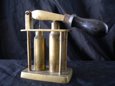
Munitions, Cartridge reloader
... This has a wooden handle The arm of the lever has a small protusion on the bottom which pushes into the opening of one of the pillars. ...This has a wooden handle The arm of the lever has a small protusion on the bottom which pushes into the opening of one of the pillars. ...This cartridge re-loader is most likely for loading 12 gauge shotgun shells. It is not known if it was for private or military use. This cartridge re-loader has been in the collection of the Warrnambool and District Historical Society for many years but it has no known local provenance. It is an interesting relic from times past. This is a brass cartridge re-loader. It has a rectangular brass base with four brass columns supporting a rectangular top with a hollow middle. The columns of the casing are affixed with metal screws. Inside this protective casing are two cartridge-shaped brass pillars, one with a metal spike at the end and one with a small opening at the top. Both of these pillars are fixed to the base of the protective casing. Over-arching these two objects is a brass lever hinged at the end. This has a wooden handle The arm of the lever has a small protusion on the bottom which pushes into the opening of one of the pillars. It also has a small indentation which fits into the spike of the other pillar. ‘12’ history of warrnambool, cartridge re-loader -
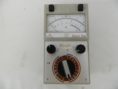 Kiewa Valley Historical Society
Meter Multi General Purpose, circa mid to late 1900's
... This is a large(hand held) device due to the mechanical movement system within and the large size of its electronic components of its circuitry.There are two black bake-lite push buttons operating the wire inserts Positive/negative leads at the top. ...This is a large(hand held) device due to the mechanical movement system within and the large size of its electronic components of its circuitry.There are two black bake-lite push buttons operating the wire inserts Positive/negative leads at the top. ...This general purpose Multi-meter was manufactured after 1950 and used by the SEC Vic (Kiewa Hydro Electricity Scheme) from that date until late 1900's. It was used to measure very small voltages associated with the operation of the various Hydro Generators. The readings were able to be shown by the resistor in use in the current circuit. During this time period, high quality testing instruments were either sourced from Europe or England. This particular meter was manufactured in the Netherlands. This type of "old" analogue meter was replaced by digital meters whose electronic components are a fraction of the size of the older analogue ones.This analog General Purpose multi-meter is quite a large (for handheld mobile) apparatus which permits the easy monitoring of electrical variations within the large SEC Victoria Hydro Scheme's electrical generators. These generators are powered by the hydro force of "stored" water at a higher altitude. The establishment of both the NSW and Victorian Hydro schemes was achieved from the mid 1900's to the 1960's. At this point in time the need for additional power sources to quench both an industrial and domestic demand for electricity was purely an economic and not and environmental (carbon reduction) factor. This hydro scheme was instigated by "the Government of the day" as a bold move and was the major force of the World War II refugee and "technical" workforce inclusion of skilled and unskilled migration into the Australian environment. Although this mass "invasion" of workers with families was thought of in some circles as intrusive, the expansion of population post war years and its integration into the Australian rural sector, produced the multi- lingual multi-cultural diversity of later years.This General Purpose Multimeter is an analogue meter i.e. it has a needle arm that moves across a scale of divisions. This is a large(hand held) device due to the mechanical movement system within and the large size of its electronic components of its circuitry.There are two black bake-lite push buttons operating the wire inserts Positive/negative leads at the top. The meter (protected with a glass window) has clearly marked graduations (top - volts, bottom amperes). Below this are two bake-lite dials (left "potentiometer the right one measuring range selector). Below this is a "dial" switch to input the desired resistance measuring range "V" Front "H&B ELIMA" and to the right Elavi 15n. 0n the front side is a label "STATE ELECTRICITY COMMISSION OF VICTORIA TRANSMISSION DEPT E.C.No." On the bottom of the base is a stenciled layout of the battery "layout" including the fuse . The information notice is presented in five languages starting with German, English,French, Italian, Spanish and Dutchsec vic kiewa hydro scheme, alternate energy supplies, alpine population growth -
 Bendigo Historical Society Inc.
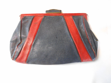
Textile - ACCESSORIES COLLECTION: LADIES HANDBAG, 1930's
... Metal frame for opening covered in red leather with gold coloured metal trim on front with push clasp (5 cm x 1 cm) with blue leather trim. ...Metal frame for opening covered in red leather with gold coloured metal trim on front with push clasp (5 cm x 1 cm) with blue leather trim. ...Textiles. Navy blue and red leather handbag. Body of handbag of navy leather with 2 cm diagonal strips of red leather across each corner front and bag. Side seams have red leather cord trim. Metal frame for opening covered in red leather with gold coloured metal trim on front with push clasp (5 cm x 1 cm) with blue leather trim. Opening tab on front. Inside lined with brown cotton fabric.Central swinging hinged coin purse and one gathered side pocket.Insde purse is a 9.5 cm lead pencil and a pen nib. Manufactured by MILADI HANDBAGS.Cloth label inside bag 'Miladi Handbags'textiles, domestic, ladies navy blue and red leather handbag -
 Dutch Australian Heritage Centre Victoria
Herring Cart (haringkarretje)
... Main body also has a support at both ends and a handle for pushing the cart. At other end is preparation area with a hole for discarding fish waste into the bucket which is hanging below. ...Main body also has a support at both ends and a handle for pushing the cart. At other end is preparation area with a hole for discarding fish waste into the bucket which is hanging below. ...Souvenir, home made with jigsaw, celebrating Dutch national delicacy. These carts are seen in streets and markets throughout the Netherlands during herring season.Balsa wood model of a herring cart with 2 spoked wheels. Main body has two compartments covered with circular lids, surmounted by rack holding 3 herring barrels in the Dutch national colours of red ,white and blue. At top of rack a fish-shaped advertising salt and sour herrings. Main body also has a support at both ends and a handle for pushing the cart. At other end is preparation area with a hole for discarding fish waste into the bucket which is hanging below. A checked tea towel hangs off the preparation area. Next to the cart is white pot with a lid possibly for holding chopped onions. -
 Melbourne Tram Museum
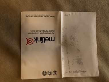
Document - Folder with papers, Metlink, "Public Transport Challenge", Jun, 2006
... . - Two plastic identity tag holders with Metlink lanyards, a yellow sheet marked "Public Transport Challenge" and a phone list. .2 - a Metlink card .3 - Pamphlet - "The Powers of Public Transport Authorised Officers" - see Reg Item 1254 .4 - Pamphlet or book - "Fares and travel guide 2006" - see Reg Item 1049.5 .5 - Pamphlet - two fold DL - promoting Metlink, partnership and containing a push through magnetic composite vehicle. .6 -Pamphlet - single DL - promoting the Metlink partnership with an image of a composite vehicle..... - Two plastic identity tag holders with Metlink lanyards, a yellow sheet marked "Public Transport Challenge" and a phone list. .2 - a Metlink card .3 - Pamphlet - "The Powers of Public Transport Authorised Officers" - see Reg Item 1254 .4 - Pamphlet or book - "Fares and travel guide 2006" - see Reg Item 1049.5 .5 - Pamphlet - two fold DL - promoting Metlink, partnership and containing a push through magnetic composite vehicle. .6 -Pamphlet - single DL - promoting the Metlink partnership with an image of a composite vehicle. ...White plastic folder marked "Metlink" with various logos and contact details containing: 1. - Two plastic identity tag holders with Metlink lanyards, a yellow sheet marked "Public Transport Challenge" and a phone list. .2 - a Metlink card .3 - Pamphlet - "The Powers of Public Transport Authorised Officers" - see Reg Item 1254 .4 - Pamphlet or book - "Fares and travel guide 2006" - see Reg Item 1049.5 .5 - Pamphlet - two fold DL - promoting Metlink, partnership and containing a push through magnetic composite vehicle. .6 -Pamphlet - single DL - promoting the Metlink partnership with an image of a composite vehicle.trams, tramways, metlink, public transport, events, competition -
Tatura Irrigation & Wartime Camps Museum
Toy Truck, Rev. Friedrich Schroettler
... We towed it around the farm behind push bikes, etc. In the early 1960's I worked with Lutheran Mission New Guinea and had the pleasure of knowing Rev. ...We towed it around the farm behind push bikes, etc. In the early 1960's I worked with Lutheran Mission New Guinea and had the pleasure of knowing Rev. ...This fire truck was made by Rev. Friedrich Schoettler, a Missionary with Lutheran Mission at Ammele and Wanjma in New Guinea. He fled to Australia, from the Japanese, during WW2, being a German national. He was interned at Tatura, Victoria, where the internees made toys to sell for spending money. This truck was given to me, Don Kuhne, by my parents for Christmas about 1944. I am surprised that it lasted as long. My brothers used it. We towed it around the farm behind push bikes, etc. In the early 1960's I worked with Lutheran Mission New Guinea and had the pleasure of knowing Rev. Schoettler, helping with aerial food drops to his small mission station.Maroon truck, yellow radiator, black running boards and mudguards, green tray, 2 wind up handles with a pulley and cord which operates an extension ladder mounted on the tray of the truck. SA 3012 SA 3012 on back of truck.rev. friedrich schoettler, lutheran missions new guinea, don kuhne, camp 3 internees -
 Bendigo Historical Society Inc.
Newspaper - Fortuna Articles - "A Vision for Fortuna Villa", Feb 2009
... The Department of Defence has delayed the assessment of Fortuna Villa, pushing the expected completion date to August, with the sale now planned for late in the year. ...The Department of Defence has delayed the assessment of Fortuna Villa, pushing the expected completion date to August, with the sale now planned for late in the year. ...The Department of Defence has delayed the assessment of Fortuna Villa, pushing the expected completion date to August, with the sale now planned for late in the year. Initial hopes were to finish assessments by December of the previous year, but this timeline was not met. Multiple assessments are required to understand the property's characteristics, and the Defence Department emphasizes the importance of thoroughness.The first draft of these assessments is still incomplete, and the property also needs to be valued before any sale can proceed. The Villa Fortuna Action Group, led by president Merle Hall, is aware of the delays and is awaiting the audit assessment results. The group plans to lobby the City of Greater Bendigo to support their proposal for the property's future use and is preparing a more detailed submission for council consideration.Fortuna Articles - "A Vision for Fortuna Villa" Feb 2009 The Bendigo Advertiser by Nino Bucci, picture Julian Prowd This item contains the following: 11217.37a Colour Photo of Fortuna 11217.37b Part of Page - "A Vision for Fortuna Villanon-fictionbendigo, fortuna, george lansell, villa fortuna action group, merle hall -
 Kiewa Valley Historical Society
Tape Measure, mid 1900s
... World War II, when Australia had to defend its own boarders that the political push for self sufficiency of manufactured goods started local production. ...World War II, when Australia had to defend its own boarders that the political push for self sufficiency of manufactured goods started local production. ...This item predates the change of Imperial measure (England -1824) to decimal measure (Europe) in Australia (1970 to 1988). This item was manufactured in England as, was the majority of measuring tool and equipment. It was not until the late 1950s that other countries e.g. United States and Europe provided the same type of manufactured tools for the Australian market. World War II, when Australia had to defend its own boarders that the political push for self sufficiency of manufactured goods started local production. Workers in the Kiewa Valley had always relied on the high quality of tools and manufactured goods coming from England. From the middle to late 1950s migration by skilled workers from a war torn Europe provided the source of manpower for the expansion of the manufacturing industries in Australia.The requirement of an accurate measuring tool has always been critical. This item was used at the time when Australia was using the British Imperial measurements. Accurate measurements by carpenters and other trades people for both town and rural needs was just as critical as for the larger cities. The transition period from Imperial to metric was a period of over four years but it still presented those who had used the Imperial measurements for a longer period in their trades with a dual system of measurement for a longer time(usually up to their retirement) Other nations still using Imperial measurements kept the transition from Imperial to metric alive (the UK and USA still uses Imperial measurements in 2012)Retractable metallic wired tape measure within a leather casing. Length of tape is 66 feet. Brass fittings on casing(winder and back plate)Tape on one side marked in inches and feet and on the other in links. Winder lever marked "66ft No 401" on front and arrow with"wind this way". Leather cover marked "John R A Bone & Sons Birmingham England" on reverse side "Metallic wired tape R A Bone & Sons"wired tape measure, tool, mobile tool, construction tool -
 Lara RSL Sub Branch
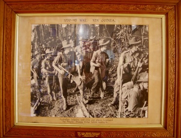
Photograph, Australian infantry in New Guinea 1939/45 war
... Once the situation on the Huon Peninsula stabilised in late 1943, the 7th Division had pushed into the Markham and Ramu Valleys towards the Finisterre Range with a view to pushing north towards the coast around Bogadjim, where they would meet up with Allied forces advancing around the coast from the Huon Peninsula, before advancing towards Madang....Once the situation on the Huon Peninsula stabilised in late 1943, the 7th Division had pushed into the Markham and Ramu Valleys towards the Finisterre Range with a view to pushing north towards the coast around Bogadjim, where they would meet up with Allied forces advancing around the coast from the Huon Peninsula, before advancing towards Madang. ...The Battle of the Shaggy Ridge was part of the Markham and Ramu Valley – Finisterre Range campaign, consisting of a number of actions fought by Australian and Japanese troops in Papua New Guinea in World War II. Following the Allied capture of Lae and Nadzab, the Australian 9th Division had been committed to a quick follow up action on the Huon Peninsula in an effort to cut off the withdrawing Japanese. Once the situation on the Huon Peninsula stabilised in late 1943, the 7th Division had pushed into the Markham and Ramu Valleys towards the Finisterre Range with a view to pushing north towards the coast around Bogadjim, where they would meet up with Allied forces advancing around the coast from the Huon Peninsula, before advancing towards Madang.In late December 1943, the Australian offensive to take Shaggy Ridge began, focused on an attack on The Pimple.[13] The Pimple was one of three rocky outcrops, held by the Japanese on the ridge line.Framed Photograph of Australian infantry waiting while our planes" bombard the Pimple,"Shaggy Ridge before moving in. Australian infantry waiting while our planes" bombard the Pimple,"Shaggy Ridge before moving in. THE LARA BRANCH R.S.S.I.L.A. FROM MRS HAMILTON CALVERT =MEMORIES=ww2, papua new guinea, world war 2, lara r.s.l., photographs, australian infantry, shaggy ridge -
 Eltham District Historical Society Inc
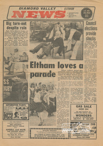
Newspaper clipping, Eltham loves a parade, Diamond Valley News (Eltham), Vol. 33, No. 32, 14 August 1979, p1, 1979
... Feature news story about 1979 Eltham Parade with photo of Society members Joh Ebeli and Russell Yeoman pushing Peter Bassett-Smith along in a wheelbarrow. ...Feature news story about 1979 Eltham Parade with photo of Society members Joh Ebeli and Russell Yeoman pushing Peter Bassett-Smith along in a wheelbarrow. ...Feature news story about 1979 Eltham Parade with photo of Society members Joh Ebeli and Russell Yeoman pushing Peter Bassett-Smith along in a wheelbarrow. Others featured were Eltham Rugby club float and Anne Mandel of the Slovenian Association of Melbourne. Other story on "Council elections provide shocks" featured the defeat of Eltham sitting councillors, Ken Hines and Helen Wells with Shire president Cr, Robert Marshall returned with a commanding majority. Reverse side (p2) story "Laughing cop no softy" is a feature article on Tony Zalewski of Greensborough CIB who was the key policeman involved in a hour-long siege in Norfolk Crescent, Bundoora in 1978 and for which he received the Victoria Police Valour AwardNewsprint page1979, anne mandel, ansell and muir, bundoora, elections, eltham festival, eltham rugby football club, greensborough cib, helen wells, joh ebeli, ken hines, lyon bros ford, norfolk crescent, parade floats, peter bassett-smith, robert marshall, russell yeoman, shire of diamond valley, shire of eltham, shire of eltham historical society, siege, slovenian association of melbourne, tony zalewski, victoria police valour award -
 Bendigo Historical Society Inc.
Newspaper - LONG GULLY HISTORY GROUP COLLECTION: SHOWCASING OUR PAST
... Weekender article from the Bendigo Advertiser 20/2/1999 mentioning the push for a museum for Bendigo by John Gascoigne. ...History House 11 Mackenzie Street Bendigo goldfields BENDIGO History long gully history group The Long Gully History Group - Showcasing Our Past Bendigo Advertiser 20/2/1999 John Gascoigne Golden Dragon Museum Bendigo Pottery RSL Memorial Hall Central Deborah Gold Mine Greater City's Heritage and Historical Societies Kathryn Mackenzie Bendigo Tourism Inc Heidi Teague German Heritage Society Eureka Museum Joan Bolton David Bolton Bolton Bros Joan O'Shea Lister House Northern District School of Nursing Graduates Association Department of Human Services Public Records Office Bendigo Hospital Cliff Binks School of Mines Bendigo Regional Institute of TAFE Frank Cusack Bendigo Junior Technical School National Trust Chambers Information Centre Commonwealth Bank City of Greater Bendigo Museum Victoria Andrew Paul Sir John Quick Jenny Whitelaw Peter Tangey Fortuna George Lansell Army's Topographical Mapping Unit A Steele Weekender article from the Bendigo Advertiser 20/2/1999 mentioning the push for a museum for Bendigo by John Gascoigne. ...Weekender article from the Bendigo Advertiser 20/2/1999 mentioning the push for a museum for Bendigo by John Gascoigne. People including Kathryn Mackenzie, , Heidi Teague, Joan Bolton, David Bolton, Joan O'Shea, Cliff Binks, Frank Cusack, Ted Barkmeyer, Andrew Paul and Peter Tangey were interviewed. There is a colour photo of Joan Bolton with an old printing machine and a black and white photo looking up Mitchell Street. On the back of this page there is another item relating to preserving Bendigo's Past, (from Weekender 17). A black and white photo at the top of the page shows Bendigo in the 1860s looking up Mitchell Street, (Photo courtesy of Frank Cusack).bendigo, history, long gully history group, the long gully history group - showcasing our past, bendigo advertiser 20/2/1999, john gascoigne, golden dragon museum, bendigo pottery, rsl memorial hall, central deborah gold mine, greater city's heritage and historical societies, kathryn mackenzie, bendigo tourism inc, heidi teague, german heritage society, eureka museum, joan bolton, david bolton, bolton bros, joan o'shea, lister house, northern district school of nursing graduates association, department of human services, public records office, bendigo hospital, cliff binks, school of mines, bendigo regional institute of tafe, frank cusack, bendigo junior technical school, national trust chambers, information centre, commonwealth bank, city of greater bendigo, museum victoria, andrew paul, sir john quick, jenny whitelaw, peter tangey, fortuna, george lansell, army's topographical mapping unit, a steele -
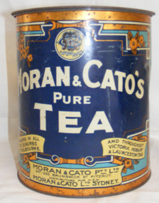 Cheese World Museum
Tin, tea
... Dark blue cylindrical tin with push-on lid decorated with a bronze ring around the top and bottom for retail tea sales. ...Reverse: Cakes On bottom: A24 Dark blue cylindrical tin with push-on lid decorated with a bronze ring around the top and bottom for retail tea sales. ...This tea tin is part of the Uebergang Collection. The collection is the property of the 'Ray & Joyce Uebergang Foundation' and was held in store for several years before being transferred to the care of Warrnambool Cheese and Butter Factory Company Ltd's Cheese World Museum. The Uebergang family came from Silesia in 1848 and were early settlers in the Allansford area. The Uebergangs purchased Tooram Park in 1912 and lived there until it was sold following the death of the last member of the family in 1994. The family often re-used, recycled and repaired items. The tea tin is an example of re-use. Moran & Cato was Dark blue cylindrical tin with push-on lid decorated with a bronze ring around the top and bottom for retail tea sales. The tin was sold by retail firm Moran & Cato and is decorated with their name in large white lettering on the front, and the address in scrolls at the bottom. The firm's logo/trade mark is featured in a circle at the top with a flower design each side. The logo/trade mark has the letters M & C intertwined and the company motto in a scroll below. The tin was designed to be used for storage once empty and is marked on the back with the word 'Cakes' in a cream scroll across the centre. The top half of this side is light blue and the bottom half dark blue.Trade mark: We Keep Troth Moran & Cato's Pure Tea/Branches in all suburbs of Melbourne and throughout Victoria, Hobart (Tas). At base: Moran & Cato Pty Ltd/277 Brunswick St/Fitzroy. Distributors for NSW. Moran & Cato Ltd Sydney. Reverse: Cakes On bottom: A24uebergang, tins, tea, moran & cato, recycling -
 Federation University Historical Collection
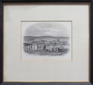
Artwork, other - Artwork (framed), Sandhurst by S.T. Gill, 1857
... In the mid ground a fledgling townscape is evident whole a man rides a horse along a thoroughfare, along with a small bullock team, and a man pushing a wheelbarrow. The scenefeatures a large number of flagpoles, and tents are visible along the horizon line. ...In the mid ground a fledgling townscape is evident whole a man rides a horse along a thoroughfare, along with a small bullock team, and a man pushing a wheelbarrow. The scenefeatures a large number of flagpoles, and tents are visible along the horizon line. ...Sandhurst is the early name for the Victorian goldfield town of Bendigo. The original was published by Melbourne's Sands and Kenny Melbourne in 1857, and the plate from "Victoria Illustrated" by S.T. Gill. Balck and white steel engraving of a work by Samuel Thomas Gill showing a scene in early Bendigo. In the foreground a woman sits on a fallen tree holding a baby and talking to a small girl, while two men stand nearby discussing words on a paper. A sign on the fence declares 'Gov Sale Land'. In the mid ground a fledgling townscape is evident whole a man rides a horse along a thoroughfare, along with a small bullock team, and a man pushing a wheelbarrow. The scenefeatures a large number of flagpoles, and tents are visible along the horizon line. The image is engraved "S.T.Gill, del." in the lower left; "J. Tingle sc" in the lower right, and the title is engraved below image. bendigo, sandhurst, samuel thomas gill, s.t. gill, j. tingle, goldfield, bullock team, horse and rider -
 Ballarat Tramway Museum
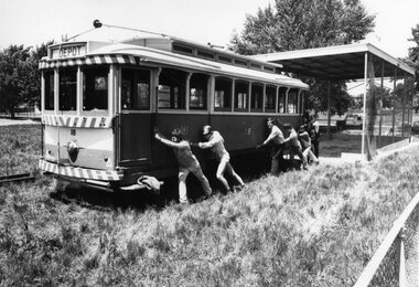
Photograph - Black & White Photograph/s, The Courier Ballarat, 2/11/1982 12:00:00 AM
... Photo has a number of BTPS members "pushing" the tram out of the shed. Photo taken 2/11/1982? ...Photo has a number of BTPS members "pushing" the tram out of the shed. Photo taken 2/11/1982? ...Yields information about the recovery of No. 18 from Sebastopol, its storage facility and some of the people who were involved on the day.Black and White copy photograph of a newspaper photograph taken by The Courier of No. 18 being moved from Victory Park Sebastopol from the shed that it was sitting in. Photo has a number of BTPS members "pushing" the tram out of the shed. Photo taken 2/11/1982? published 4/11/1982. Photo used in the 1982-1983 annual report which dates the photo as the 2/11/1982. Copy of newspaper clipping photo appeared in, not held by Museum at date of cataloguing. Collected by Alan Bradley from the Ballarat Courier early 1980's. See Excel file "Record of Ballarat Courier Photos BTM era" (Archive Documents) for source of details.On rear stamped "Copyright, The Ballarat Courier Proprietary Limited." and in pencil "1 FC top"tramways, trams, btps, tram recovery, sebastopol, trams, tram 18 -
 Melbourne Tram Museum
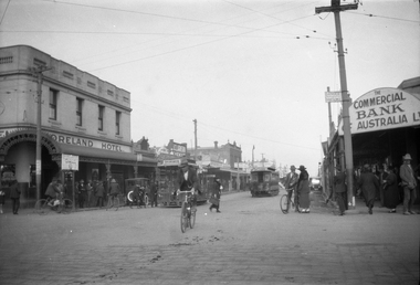
Negative, Ellis Collection, c1956
... Saloon car is No. 183 with the conductor pushing the car. The grip car has the destination of Brunswick and the saloon Flinders St? ...Saloon car is No. 183 with the conductor pushing the car. The grip car has the destination of Brunswick and the saloon Flinders St? ...Negative (120) of the intersection of Moreland Road and Sydney Road, Brunswick, during the 1920's. In the view is a cable tram set shunting. A tramway employee and two boys at the front of the grip car seem to be manipulating something. Saloon car is No. 183 with the conductor pushing the car. The grip car has the destination of Brunswick and the saloon Flinders St? Note the two steel tramway poles and overhead for the North Coburg electric tram service from Moreland Rod into Sydney Road. In the background is the Moreland Hotel, Clarkson chemist and the Commercial Bank of Australia. An low resolution A4 laminated was received with the negatives. Hi Res image filed in the dbtext/hawthtramcoll/Large Images/htd3589large.jpgtrams, tramways, brunswick, cable trams, sydney rd, moreland rd, tram 183 -
 Kiewa Valley Historical Society
Photograph - Kiewa River in flood at Clover Dam
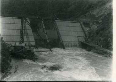
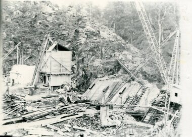
... As part of the push to cut electricity costs and diversify supply, the Victorian Government (circa 1930) implemented the conversion strategy from mainly brown coal supply to hydro - electricity. ...Kiewa Valley Historical Society Mount Beauty Information Centre 31 Bogong High Plains Rd Mt Beauty high-country As part of the push to cut electricity costs and diversify supply, the Victorian Government (circa 1930) implemented the conversion strategy from mainly brown coal supply to hydro - electricity. ...As part of the push to cut electricity costs and diversify supply, the Victorian Government (circa 1930) implemented the conversion strategy from mainly brown coal supply to hydro - electricity. The Kiewa Hydroelectric Scheme became the largest scheme of its kind in the State Of Victoria and the second largest scheme in Australia. Clover Dam and Power Station were built by the State Electricity Commission of Victoria as part of the Kiewa Hydro Electric Scheme from the late 1930's to the early 1940's. This dam was constructed to supply water to feed four turbines (62 mega watts) at the West Kiewa Power Station. This was at the forefront of sustainable "Green" energy. Costs associated with power supplies is still a major incentive of governments, however environmentally friendly alternatives such as wind and nuclear have also made inroads. The Kiewa valley and its surrounding alpine catchment were looked at(Victorian State Government), from the beginning of the twentieth century as a source of alternate power for an ever-increasing demand for electricity by growing population and heavy industrial areas within Melbourne City and State regions. Construction of dams, such as Clover Dam provided the large quantity holding areas of water required to turn the turbines at the various power stations to provide the electricity needed. The impact of these controls by moderating water run-off from the alpine regions is beneficial in reducing flooding from thawing of snow on the alps. This by-product allows agriculture and grazing to be less vulnerable to seasonal flooding thereby resulting in a more stable annual production level.Black and white photograph of Clover Dam with Kiewa River in flood. .5mm white boarder on 3 sides of photo.Handwritten on back of photograph in black pen - Kiewa in flood. Clover Dam.clover dam, secv -
 Kiewa Valley Historical Society
Photograph - Clover Dam
... As part of the push to cut electricity costs and diversify supply, the Victorian Government (circa 1930) implemented the conversion strategy from mainly brown coal supply to hydro - electricity. ...Kiewa Valley Historical Society Mount Beauty Information Centre 31 Bogong High Plains Rd Mt Beauty high-country As part of the push to cut electricity costs and diversify supply, the Victorian Government (circa 1930) implemented the conversion strategy from mainly brown coal supply to hydro - electricity. ...As part of the push to cut electricity costs and diversify supply, the Victorian Government (circa 1930) implemented the conversion strategy from mainly brown coal supply to hydro - electricity. The Kiewa Hydroelectric Scheme became the largest scheme of its kind in the State Of Victoria and the second largest scheme in Australia. Clover Dam and Power Station were built by the State Electricity Commission of Victoria as part of the Kiewa Hydro Electric Scheme from the late 1930's to the early 1940's. This dam was constructed to supply water to feed four turbines (62 mega watts) at the West Kiewa Power Station. This was at the forefront of sustainable "Green" energy. Costs associated with power supplies is still a major incentive of governments, however environmentally friendly alternatives such as wind and nuclear have also made inroads. The Kiewa valley and its surrounding alpine catchment were looked at(Victorian State Government), from the beginning of the twentieth century as a source of alternate power for an ever-increasing demand for electricity by growing population and heavy industrial areas within Melbourne City and State regions. Construction of dams, such as Clover Dam provided the large quantity holding areas of water required to turn the turbines at the various power stations to provide the electricity needed. The impact of these controls by moderating water run-off from the alpine regions is beneficial in reducing flooding from thawing of snow on the alps. This by-product allows agriculture and grazing to be less vulnerable to seasonal flooding thereby resulting in a more stable annual production level.Black and white photograph of Clover Dam buildings and Kiewa River. Has a .4cm white border around photograph Printed on bottom left corner of photograph in white - Clover Flatclover dam, secv -
 Kiewa Valley Historical Society
Photographs x 2 - Clover Dam, Circa 1940's
... As part of the push to cut electricity costs and diversify supply, the Victorian Government (circa 1930) implemented the conversion strategy from mainly brown coal supply to hydro - electricity. ...Kiewa Valley Historical Society Mount Beauty Information Centre 31 Bogong High Plains Rd Mt Beauty high-country As part of the push to cut electricity costs and diversify supply, the Victorian Government (circa 1930) implemented the conversion strategy from mainly brown coal supply to hydro - electricity. ...As part of the push to cut electricity costs and diversify supply, the Victorian Government (circa 1930) implemented the conversion strategy from mainly brown coal supply to hydro - electricity. The Kiewa Hydroelectric Scheme became the largest scheme of its kind in the State Of Victoria and the second largest scheme in Australia. Clover Dam and Power Station were built by the State Electricity Commission of Victoria as part of the Kiewa Hydro Electric Scheme from the late 1930's to the early 1940's. This dam was constructed to supply water to feed four turbines (62 mega watts) at the West Kiewa Power Station. This was at the forefront of sustainable "Green" energy. Costs associated with power supplies is still a major incentive of governments, however environmentally friendly alternatives such as wind and nuclear have also made inroads. The Kiewa valley and its surrounding alpine catchment were looked at(Victorian State Government), from the beginning of the twentieth century as a source of alternate power for an ever-increasing demand for electricity by growing population and heavy industrial areas within Melbourne City and State regions. Construction of dams, such as Clover Dam provided the large quantity holding areas of water required to turn the turbines at the various power stations to provide the electricity needed. The impact of these controls by moderating water run-off from the alpine regions is beneficial in reducing flooding from thawing of snow on the alps. This by-product allows agriculture and grazing to be less vulnerable to seasonal flooding thereby resulting in a more stable annual production level. Photographs also document early engineering and building techniques used in the construction of dams and power stations during the 1940’s and 1950’s. Note the lack of safety equipment and suitable work attire worn by construction workers on the sites 1. Black and white photograph of Clover Dam under construction. Has a .5cm white border around photo 2. Black and white photograph of Clover Dam under construction showing workmen at work. Has a .5cm white border around photo Written in pencil on back of both photographs - Clover Damclover dam, secv -
 Kiewa Valley Historical Society
Photograph - Folder of Photographs (KVHS 1150 A - F) – Photocopied set of black and white photographs from the display folder (pages 1 - 8) put together by KVHS to document life on the Kiewa Valley Hydro-electric Scheme
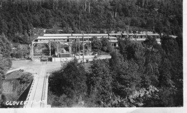
... Although the Kiewa Hydro-Electric Scheme was first proposed in 1911, construction did not commence until 1938. As part of the push to cut electricity costs and diversify supply, the Victorian Government (circa 1930) initiated the conversion from primarily brown coal supply to hydro – electricity. ...Kiewa Valley Historical Society Mount Beauty Information Centre 31 Bogong High Plains Rd Mt Beauty high-country Although the Kiewa Hydro-Electric Scheme was first proposed in 1911, construction did not commence until 1938. As part of the push to cut electricity costs and diversify supply, the Victorian Government (circa 1930) initiated the conversion from primarily brown coal supply to hydro – electricity. ...Although the Kiewa Hydro-Electric Scheme was first proposed in 1911, construction did not commence until 1938. As part of the push to cut electricity costs and diversify supply, the Victorian Government (circa 1930) initiated the conversion from primarily brown coal supply to hydro – electricity. Field investigations during the 1940’s resulted in a new proposal for a scheme that had more than double the capacity of the 1938 scheme. The Kiewa Hydroelectric Scheme became the largest scheme of its kind in the State Of Victoria and the second largest scheme in Australia. The number of personnel involved in the planning and construction of the scheme increased dramatically. During the late 1940’s, most activity centred around the construction of the West Kiewa Power Station, Rocky Valley Reservoir, McKay Creek Power Station and the Bogong Creek Aqueduct.A common thread across all the larger hydro scheme constructions was the need for workers, both qualified and unqualified who came from around the world seeking a new life for themselves and their families. New accommodation and facilities were required for the army of workers engaged in construction in often remote and wild areas. The SEC had a high demand for timber, and set up the first of a number of sawmills at Bogong Creek in 1939 and set up the first hardwood logging in the headwaters of the Kiewa River. These new ‘towns’ such as Mt Beauty and Bogong, survived, serving the needs of operational personnel and their families, and expanding with growth of new industries. Mount Beauty, and to a lesser extent Bogong, are among these places. Large A3 size spiral bound display folder containing 21 of 58 pages of photocopied black and white photographs of various aspects of the early days of the Kiewa Valley Hydro-electric scheme including equipment, various work sites and photographs of workers and their families. 1-Front page; 2-Security gate at Mt Beauty Camp; 3-Channel 1 on East Kiewa River; 4-Junction Dam – Diversion Tunnel Inlet; 5-Sawmill; 6- Homan’s Gap Sawmill; 7 Junction Dam: 8-Homan Dam Site-Diamond Drilling on River Buttress; 9- Homan Dam Site View Upstream 10-Homan Dam Investigation Camp 1-Windsor & Newton Visual Diary 60 sheet (120 pages) 11’ x 14’ 280 x 356mm 110 GSM Acid Free Drawing Paper 2-1940-Security Gate on Mt Beauty side of Kiewa River bridge. Part of old Mt Beauty camp and mess in background 3- STATE ELECTRICITY COMMISSION OF VICTORIA Date; 11.3.40 Time: 10.30am No K35 Kiewa Hydro Electric Works. Diverting East Kiewa River into Channel Page number 1 4-STATE ELECTRICITY COMMISSION OF VICTORIA Date: 5.4.40 Time: Noon No K58 Kiewa Hydro Electric Works. Junction Dam – Diversion Tunnel Inlet – Normal Flow Page number 2 5- STATE ELECTRICITY COMMISSION OF VICTORIA Date: 19.8.42 Time: 2.30pm No K883 Kiewa Hydro Electric Works. Sawmill – General View Page number 3 6- STATE ELECTRICITY COMMISSION OF VICTORIA Date: 12.1.42 Time: 2.00pm No K540 Kiewa Hydro Electric Works. Homan’s Gap Sawmill – General View Page number 4 7- STATE ELECTRICITY COMMISSION OF VICTORIA Date: 12.1.42 Time: 2.00pm No K540 Kiewa Hydro Electric Works. Junction Dam – General View looking upstream Page number 5 8- STATE ELECTRICITY COMMISSION OF VICTORIA Date: 16.11.45 Time: 10.32amm No K52153 Kiewa Hydro Electric Works Homan Dam Site – Diamond Drilling on River Buttress Page number 6 9-STATE ELECTRICITY COMMISSION OF VICTORIA Date: 15.1.45 Time: 4.10pm No K1781 Kiewa Hydro Electric Works Homan Dam Site – View Upstream Page number 7 10- STATE ELECTRICITY COMMISSION OF VICTORIA Date: 15.1.45 Time: 4.10pm No K1781 Kiewa Hydro Electric Works Homan Dam Investigation Camp 1944 – 1945 Page number 8 secv; kiewa hydro electric scheme; mt beauty; bogong; construction work; -
 Kiewa Valley Historical Society
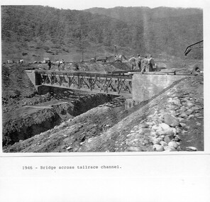
Photograph - Folder of Photographs – Photocopied set of black and white photographs (pages 9 - 18) from the display folder put together by KVHS to document life on the Kiewa Valley Hydro-electric Scheme
... Although the Kiewa Hydro-Electric Scheme was first proposed in 1911, construction did not commence until 1938. As part of the push to cut electricity costs and diversify supply, the Victorian Government (circa 1930) initiated the conversion from primarily brown coal supply to hydro – electricity. ...Kiewa Valley Historical Society Mount Beauty Information Centre 31 Bogong High Plains Rd Mt Beauty high-country Although the Kiewa Hydro-Electric Scheme was first proposed in 1911, construction did not commence until 1938. As part of the push to cut electricity costs and diversify supply, the Victorian Government (circa 1930) initiated the conversion from primarily brown coal supply to hydro – electricity. ...Although the Kiewa Hydro-Electric Scheme was first proposed in 1911, construction did not commence until 1938. As part of the push to cut electricity costs and diversify supply, the Victorian Government (circa 1930) initiated the conversion from primarily brown coal supply to hydro – electricity. Field investigations during the 1940’s resulted in a new proposal for a scheme that had more than double the capacity of the 1938 scheme. The Kiewa Hydroelectric Scheme became the largest scheme of its kind in the State Of Victoria and the second largest scheme in Australia. The number of personnel involved in the planning and construction of the scheme increased dramatically. During the late 1940’s, most activity centred around the construction of the West Kiewa Power Station, Rocky Valley Reservoir, McKay Creek Power Station and the Bogong Creek Aqueduct.A common thread across all the larger hydro scheme constructions was the need for workers, both qualified and unqualified who came from around the world seeking a new life for themselves and their families. New accommodation and facilities were required for the army of workers engaged in construction in often remote and wild areas. The SEC had a high demand for timber, and set up the first of a number of sawmills at Bogong Creek in 1939 and set up the first hardwood logging in the headwaters of the Kiewa River. These new ‘towns’ such as Mt Beauty and Bogong, survived, serving the needs of operational personnel and their families, and expanding with growth of new industries. Mount Beauty, and to a lesser extent Bogong, are among these places. PHYSICAL: Large A3 size spiral bound display folder containing 21 pages of photocopied black and white photographs of various aspects of the early days of the Kiewa Valley Hydro-electric scheme including equipment, various work sites and photographs of workers and their families. 1-Bridge across Tailrace Channel 1946 2-New Mess building, Mt Beauty 3-Homan’s Gap Saw Mill 4- Diamond Drilling Plant – Big Hill 5-Rocky Valley Camp-Mess Building 6-Parlimentary Party at Rocky Valley 7-No.4 Headrace Tunnel 8- Allis-Chalmers Tractor School 9- SECV Heavy Machinery lined up by road 10- No. 5 Raceline – Balasting Track with improvised truck 1-1946 – Bridge across tailrace channel Page number 9 2-New mess building, Mt Beauty 6.4.46 Page number 10 3- STATE ELECTRICITY COMMISSION OF VICTORIA Date: 10.1.47 Time: 11.40am No K2271 Kiewa Hydro Electric Works Homan’s Gap Saw Mill – Rip Saw Page number 11 4- STATE ELECTRICITY COMMISSION OF VICTORIA Date: 5.10.47 Time: 11am No K4111 Kiewa Hydro Electric Works Diamond Drilling Plant – Big Hill Page number 12 5- STATE ELECTRICITY COMMISSION OF VICTORIA Date: 11.2.48 Time: 3pm No K4277 Kiewa Hydro Electric Works Rocky Valley Camp-Mess Building Page number 13 6- STATE ELECTRICITY COMMISSION OF VICTORIA Date: 15.4.48 Time: 4.30pm No K4397 Kiewa Hydro Electric Works Parlimentary Party at Rocky Valley Page number 14 7- STATE ELECTRICITY COMMISSION OF VICTORIA Date: 22.8.48 Time: 9am No K4668 Kiewa Hydro Electric Works General view of No.4 Headrace Tunnel Page number 15 8-STATE ELECTRICITY COMMISSION OF VICTORIA Date: 5.9.49 Time: 10am No K5180 Kiewa Hydro Electric Works Allis-Chalmers Tractor School – HD 19, Mr I Crossthwaite at Controls Page number 16 9- No markings Page number 17 10- STATE ELECTRICITY COMMISSION OF VICTORIA Date: 7,12.49 Time: 4pm No K5423 Kiewa Hydro Electric Works No. 5 Raceline – Balasting Track with improvised truck. Page number 18 secv; kiewa hydro electric scheme; mt beauty; bogong; construction area -
 Kiewa Valley Historical Society
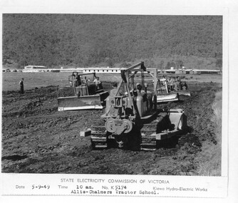
Photograph - Folder of Photographs – Photocopied set of 10 black and white photographs (pages 19 - 28) from the display folder put together by KVHS to document life on the Kiewa Valley Hydro-electric Scheme
... Although the Kiewa Hydro-Electric Scheme was first proposed in 1911, construction did not commence until 1938. As part of the push to cut electricity costs and diversify supply, the Victorian Government (circa 1930) initiated the conversion from primarily brown coal supply to hydro – electricity. ...Kiewa Valley Historical Society Mount Beauty Information Centre 31 Bogong High Plains Rd Mt Beauty high-country Although the Kiewa Hydro-Electric Scheme was first proposed in 1911, construction did not commence until 1938. As part of the push to cut electricity costs and diversify supply, the Victorian Government (circa 1930) initiated the conversion from primarily brown coal supply to hydro – electricity. ...Although the Kiewa Hydro-Electric Scheme was first proposed in 1911, construction did not commence until 1938. As part of the push to cut electricity costs and diversify supply, the Victorian Government (circa 1930) initiated the conversion from primarily brown coal supply to hydro – electricity. Field investigations during the 1940’s resulted in a new proposal for a scheme that had more than double the capacity of the 1938 scheme. The Kiewa Hydroelectric Scheme became the largest scheme of its kind in the State Of Victoria and the second largest scheme in Australia. The number of personnel involved in the planning and construction of the scheme increased dramatically. During the late 1940’s, most activity centred around the construction of the West Kiewa Power Station, Rocky Valley Reservoir, McKay Creek Power Station and the Bogong Creek Aqueduct.A common thread across all the larger hydro scheme constructions was the need for workers, both qualified and unqualified who came from around the world seeking a new life for themselves and their families. New accommodation and facilities were required for the army of workers engaged in construction in often remote and wild areas. The SEC had a high demand for timber, and set up the first of a number of sawmills at Bogong Creek in 1939 and set up the first hardwood logging in the headwaters of the Kiewa River. These new ‘towns’ such as Mt Beauty and Bogong, survived, serving the needs of operational personnel and their families, and expanding with growth of new industries. Mount Beauty, and to a lesser extent Bogong, are among these places. Large A3 size spiral bound display folder containing 21 pages of photocopied black and white photographs of various aspects of the early days of the Kiewa Valley Hydro-electric scheme including equipment, various work sites and photographs of workers and their families. 1-Allis Chalmers Tractor School 2- Gardens outside Administrative Office – Mt Beauty 3- Mt Beauty house – 1950 4-Bridge over Pretty Valley River, Bogong 5-Rocky Valley Spillway Tunnel break through 6-Ni 1 Headrace Tunnel drilling face 7-No 4 Power Station Drilling 8-Clover Dam Flood Waters 9-No1 Head Race Tunnel Portal Building 10-Clover Dam 1-STATE ELECTRICITY COMMISSION OF VICTORIA Date: 5.9.49 Time: 10amm No K5174 Kiewa Hydro Electric Works Allis Chalmers Tractor School Page number 19 2-STATE ELECTRICITY COMMISSION OF VICTORIA Date: 22.2.50 Time: 3.30pm No K5601 Kiewa Hydro Electric Works Gardens outside Administrative Office – Mt Beauty Page number 20 3-Mt Beauty house – 1950 Page number 21 4-STATE ELECTRICITY COMMISSION OF VICTORIA Date: 23.10.50 Time: 11.15am No K6331 Kiewa Hydro Electric Works Bogong-Bridge over Pretty Valley River Page number 22 5-STATE ELECTRICITY COMMISSION OF VICTORIA Date: 23.6.50 Time: 2.30pm No K5844 Kiewa Hydro Electric Works ROCKY VALLEY SPILLWAY TUNNEL BREAK THROUGH Page number 23 6-20/3/52 – No. 1 Headrace Tunnel Drilling face (E.E.E. contract) Page number 24 7-6/6/52 – No 4 Power Station – Drilling Page number 25 8-STATE ELECTRICITY COMMISSION OF VICTORIA Date: 6/6/52 Time: No K7113 Kiewa Hydro Electric Works Clover Dam Flood Waters Page number 26 9-STATE ELECTRICITY COMMISSION OF VICTORIA Date: Oct 1952 Time: No K7239 Kiewa Hydro Electric Works No. 1 HEAD RACE TUNNEL PORTAL BUILDING. Handwritten underneath – This information from Ron White-the later Principal Hydro Engineer of the SEC. Oct 1952 Location incorrect? All work on No 1 had ceased after financial crash of 1951. This photo would refer to No 4 Headrace Tunnel? Page number 27 10-STATE ELECTRICITY COMMISSION OF VICTORIA Date: Jan 1953 Time: No K7307 Kiewa Hydro Electric Works CLOVER DAM Page number 28 secv; kiewa hydro electric scheme; bogong; mt beauty; construction area -
 Kiewa Valley Historical Society
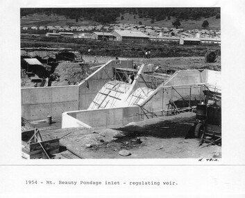
Photograph - Folder of Photographs – Photocopied set of 10 black and white photographs (pages 29 - 38) from the display folder put together by KVHS to document life on the Kiewa Valley Hydro-electric Scheme
... Although the Kiewa Hydro-Electric Scheme was first proposed in 1911, construction did not commence until 1938. As part of the push to cut electricity costs and diversify supply, the Victorian Government (circa 1930) initiated the conversion from primarily brown coal supply to hydro – electricity. ...Kiewa Valley Historical Society Mount Beauty Information Centre 31 Bogong High Plains Rd Mt Beauty high-country Although the Kiewa Hydro-Electric Scheme was first proposed in 1911, construction did not commence until 1938. As part of the push to cut electricity costs and diversify supply, the Victorian Government (circa 1930) initiated the conversion from primarily brown coal supply to hydro – electricity. ...Although the Kiewa Hydro-Electric Scheme was first proposed in 1911, construction did not commence until 1938. As part of the push to cut electricity costs and diversify supply, the Victorian Government (circa 1930) initiated the conversion from primarily brown coal supply to hydro – electricity. Field investigations during the 1940’s resulted in a new proposal for a scheme that had more than double the capacity of the 1938 scheme. The Kiewa Hydroelectric Scheme became the largest scheme of its kind in the State Of Victoria and the second largest scheme in Australia. The number of personnel involved in the planning and construction of the scheme increased dramatically. During the late 1940’s, most activity centred around the construction of the West Kiewa Power Station, Rocky Valley Reservoir, McKay Creek Power Station and the Bogong Creek Aqueduct.A common thread across all the larger hydro scheme constructions was the need for workers, both qualified and unqualified who came from around the world seeking a new life for themselves and their families. New accommodation and facilities were required for the army of workers engaged in construction in often remote and wild areas. The SEC had a high demand for timber, and set up the first of a number of sawmills at Bogong Creek in 1939 and set up the first hardwood logging in the headwaters of the Kiewa River. These new ‘towns’ such as Mt Beauty and Bogong, survived, serving the needs of operational personnel and their families, and expanding with growth of new industries. Mount Beauty, and to a lesser extent Bogong, are among these places. Large A3 size spiral bound display folder containing 21 pages of photocopied black and white photographs of various aspects of the early days of the Kiewa Valley Hydro-electric scheme including equipment, various work sites and photographs of workers and their families. 1-Mt Beauty Pondage inlet-Regulating weir 2-Langfords Gap Basalt Hill-Tunnel in quarry face.3-Rocky Valley Camp-from Engineering Office 4-Basalt Hill tunnel portal 5-No 1 Pressure Shaft Works Bench 6-No 1 Power Station 7-Overturned haulage wagons on the side of an embankment 8- Group of workers dressed in wet weather gear inside a tunnel 9-Workmen and vehicle in tunnel 10-Howman’s Gap campsite at 4,150 feet 1-1954 – Mt Beauty Pondage inlet – Regulating weir Page number 29 2-28/10/54 – Langfords Gap Basalt Hill – Tunnel in quarry face K7860 Page number 30 3-STATE ELECTRICITY COMMISSION OF VICTORIA Date: 17.8.55 Time: No K8132 Kiewa Hydro Electric Works ROCKY VALLEY CAMP – FROM ENGINEERING OFFICE Page number 31 4-28/10/54 – Basalt Hill tunnel portal K7859 Page number 32 5-No.1 Pressure Shaft Works Bench 5.7.56 Page number 33 6- No. 1 Power Station 26.4.59 Page number 34 7- No markings Page number 35 8-No markings (Wooden board on ground printed with - POLAR A.N.GELATINE DYNAMITE “75” DE 28.8.40) Page number 36 9-No markings Page number 37 10-Howman’s Gap campsite at 4,150 feet Page number 38 secv; kiewa hydro electric scheme; mt beauty; bogong; construction area -
 Kiewa Valley Historical Society
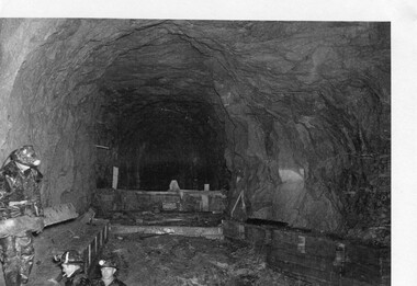
Photograph - Folder of Photographs – Photocopied set of black and white photographs (pages 49 -58) from the display folder put together by KVHS to document life on the Kiewa Valley Hydro-electric Scheme
... Although the Kiewa Hydro-Electric Scheme was first proposed in 1911, construction did not commence until 1938. As part of the push to cut electricity costs and diversify supply, the Victorian Government (circa 1930) initiated the conversion from primarily brown coal supply to hydro – electricity. ...Kiewa Valley Historical Society Mount Beauty Information Centre 31 Bogong High Plains Rd Mt Beauty high-country Although the Kiewa Hydro-Electric Scheme was first proposed in 1911, construction did not commence until 1938. As part of the push to cut electricity costs and diversify supply, the Victorian Government (circa 1930) initiated the conversion from primarily brown coal supply to hydro – electricity. ...Although the Kiewa Hydro-Electric Scheme was first proposed in 1911, construction did not commence until 1938. As part of the push to cut electricity costs and diversify supply, the Victorian Government (circa 1930) initiated the conversion from primarily brown coal supply to hydro – electricity. Field investigations during the 1940’s resulted in a new proposal for a scheme that had more than double the capacity of the 1938 scheme. The Kiewa Hydroelectric Scheme became the largest scheme of its kind in the State Of Victoria and the second largest scheme in Australia. The number of personnel involved in the planning and construction of the scheme increased dramatically. During the late 1940’s, most activity centred around the construction of the West Kiewa Power Station, Rocky Valley Reservoir, McKay Creek Power Station and the Bogong Creek Aqueduct.A common thread across all the larger hydro scheme constructions was the need for workers, both qualified and unqualified who came from around the world seeking a new life for themselves and their families. New accommodation and facilities were required for the army of workers engaged in construction in often remote and wild areas. The SEC had a high demand for timber, and set up the first of a number of sawmills at Bogong Creek in 1939 and set up the first hardwood logging in the headwaters of the Kiewa River. These new ‘towns’ such as Mt Beauty and Bogong, survived, serving the needs of operational personnel and their families, and expanding with growth of new industries. Mount Beauty, and to a lesser extent Bogong, are among these places. Large A3 size spiral bound display folder containing photocopied black and white photographs of various aspects of the early days of the Kiewa Valley Hydro-electric scheme including equipment, various work sites and photographs of workers and their families. 1-Workmen working inside one of the tunnels. 2-Workman drilling in West Kiewa Tunnel 3-Junction Dam wall construction 4&5-2B&W photographs Kiewa House residents ready to go to a ball in Mt Beauty 6-Workmen warming up in front of a fire at No 1 bench 7-Workmen being hauled in at No 4 P.S Shaft 8-No 4 Power Station – Drilling 9-Workmen eating a hot meal in the tunnel. 10-2 photographs (a)Pretty Valley camp showing workman’s huts and construction materials & (b)Worker in Langford Gap Basalt Hill Tunnel face 11-Tunnel entrance (unlabelled) with rail tracks in foreground 12- Workmen drilling at No 1 Head race tunnel-Drilling face 13- No 1 Power Station 14-Workmen at the entrance to one of the SECV tunnels under construction 1-SECV number at bottom of picture Half obscured possibly K8461 Page number 53 2-In West Kiewa Tunnel Page number 54 3- Construction of Junction Dam wall – approximately 1941 Page number 55 4&5- Residents of Kiewa House at Bogong ready to go to the ball at Mt Beauty-1946. Handwritten on a copy of the photo on opposite page Mrs Lorna Crosset filled out the names *Dad was Des Crossett – his daughter is Gael Petcopoulis Greta engaged to John broke it off. Charlie, Rosalind, Bill, Priscilla, Max Lawrence-Dad’s Boss, Mary & Max married, Mary, Kay, Gwen McPherson Mum’s boss, John McCluskey (c) At No. 5 Bench Page number 56 6- STATE ELECTRICITY COMMISSION OF VICTORIA Date: 27.2.51 Time:2.15pm No K6373 Kiewa Hydro Electric Works No. 4 P.S. Shaft – Haulage of men in buckets (b) As above Handwritten at top of photo Appendix 4 page number 57 7- STATE ELECTRICITY COMMISSION OF VICTORIA Date: 6.6.52 Time:… No K7122 Kiewa Hydro Electric Works No. 4 POWER STATION – DRILLING page number 58 8-No markings page number 59 9-(a)Handwritten under photograph Approx. 1948/49 (b) STATE ELECTRICITY COMMISSION OF VICTORIA Date: 28.10.54 Time:.. No K7860 Kiewa Hydro Electric Works LANGFORD GAP BASALT HILL TUNNEL FACE Page number 49 10-(a) No markings 11- STATE ELECTRICITY COMMISSION OF VICTORIA Date: 20.3.52 Time: No K6979 Kiewa Hydro Electric Works No. 1 HEAD RACE TUNNEL – DRILLING FACE (E.E.E. CONTRACT) ‘The Frenchies’ (E.E.E) as they were affectionately known Page number 50 12-31.5.56 No. 1 Power Station Aggregate Stock Piles. Page number 51 13&14-No markings Page number 52 secv; kiewa hydro electric scheme; bogong; mt beauty; construction area -
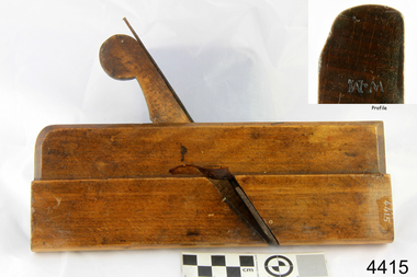
 Flagstaff Hill Maritime Museum and Village
Tool - Wood moulding Plane, Mid to late 19th century
... Large crown mouldings required planes of six or more inches in width, which demanded great strength to push and often had additional peg handles on the sides, allowing the craftsman's apprentice or other worker to pull the plane ahead of the master who guided it....Large crown mouldings required planes of six or more inches in width, which demanded great strength to push and often had additional peg handles on the sides, allowing the craftsman's apprentice or other worker to pull the plane ahead of the master who guided it. ...A moulding plane is a specialised plane used for making the complex shapes found in wooden mouldings that are used to decorate furniture or other wooden object. Traditionally, moulding planes were blocks of wear resistant hardwood, often beech or maple, which were worked to the shape of the intended moulding. The blade, or iron was likewise formed to the intended moulding profile and secured in the body of the plane with a wooden wedge. A traditional cabinetmakers shop might have many, perhaps hundreds, of moulding planes for the full range of work to be performed. Large crown mouldings required planes of six or more inches in width, which demanded great strength to push and often had additional peg handles on the sides, allowing the craftsman's apprentice or other worker to pull the plane ahead of the master who guided it.A vintage tool made by an unknown maker, this item was made commercially for firms and individuals that worked in wood and needed a tool that could produce a ornamental finish to timber. The tool was used before routers and spindle moulders came into use to produce a decorative moulding for a piece of furniture, door trims etc. or other timber items that had to be accomplished by using hand tools and in particular one of these types of planes. Profiled planes came in various shapes and sizes to achieve the required decorative finish. A significant tool from the mid to late 19th century that today is sought after by collectors. It gives us a snapshot of how furniture and other decorative finishes were created on timber by the use of hand tools. Tongue and groove match plane with metal strip affixed with 5 screws Mc Vicar stamped on end and No 2. flagstaff hill, warrnambool, shipwrecked-coast, flagstaff-hill, flagstaff-hill-maritime-museum, maritime-museum, shipwreck-coast, flagstaff-hill-maritime-village -
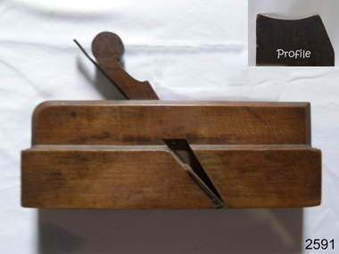
 Flagstaff Hill Maritime Museum and Village
Tool - Plane, James Hastie, Late 19th to Early 20th Century
... Large crown mouldings required planes of six or more inches in width, which demanded great strength to push and often had additional peg handles on the sides, allowing the craftsman's apprentice or other worker to pull the plane ahead of the master who guided it....Large crown mouldings required planes of six or more inches in width, which demanded great strength to push and often had additional peg handles on the sides, allowing the craftsman's apprentice or other worker to pull the plane ahead of the master who guided it. ...A moulding plane is a specialised plane used for making the complex shapes found in wooden mouldings that are used to decorate furniture or other wooden object. Traditionally, moulding planes were blocks of wear resistant hardwood, often beech or maple, which were worked to the shape of the intended moulding. The blade, or iron was likewise formed to the intended moulding profile and secured in the body of the plane with a wooden wedge. A traditional cabinetmakers shop might have many, perhaps hundreds, of moulding planes for the full range of work to be performed. Large crown mouldings required planes of six or more inches in width, which demanded great strength to push and often had additional peg handles on the sides, allowing the craftsman's apprentice or other worker to pull the plane ahead of the master who guided it.A vintage tool used before routers and spindle moulders came into use after World War ll, a time when to produce a decorative moulding for a piece of furniture was done by hand using one of these types of plane. A significant item from the mid to late 19th century that today is quite rare and sought after by collectors. It gives us a snapshot of how furniture was made predominately by hand and with tools that were themselves hand made shows the craftsmanship used to make such a unique item. Moulding Plane with metal blade attached. Made by J Hastie. Inscriptions stamped into wood. "J Hastie" "E G" "W.M" "EG" "11"flagstaff hill, warrnambool, shipwrecked-coast, flagstaff-hill, flagstaff-hill-maritime-museum, maritime-museum, shipwreck-coast, flagstaff-hill-maritime-village, j hastie, plane, wood working tool, hand tool -
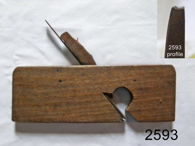
 Flagstaff Hill Maritime Museum and Village
Tool - Moulding Plane, J Hastie, 1766-1802
... Large crown mouldings required planes of six or more inches in width, which demanded great strength to push and often had additional peg handles on the sides, allowing the craftsman's apprentice or other worker to pull the plane ahead of the master who guided it....Large crown mouldings required planes of six or more inches in width, which demanded great strength to push and often had additional peg handles on the sides, allowing the craftsman's apprentice or other worker to pull the plane ahead of the master who guided it. ...A moulding plane is a specialised plane used for making the complex shapes found in wooden mouldings that are used to decorate furniture or other wooden object. Traditionally, moulding planes were blocks of wear resistant hardwood, often beech or maple, which were worked to the shape of the intended moulding. The blade, or iron was likewise formed to the intended moulding profile and secured in the body of the plane with a wooden wedge. A traditional cabinetmakers shop might have many, perhaps hundreds, of moulding planes for the full range of work to be performed. Large crown mouldings required planes of six or more inches in width, which demanded great strength to push and often had additional peg handles on the sides, allowing the craftsman's apprentice or other worker to pull the plane ahead of the master who guided it.A vintage tool used before routers and spindle moulders came into use after World War ll, a time when to produce a decorative moulding for a piece of furniture was done by hand using one of these types of plane. A significant item from the mid to late 19th century that today is quite rare and sought after by collectors. It gives us a snapshot of how furniture was made predominately by hand and with tools that were themselves hand made shows the craftsmanship used to make such a unique item. Moulding Plane Hollow type No15 J Hastie Stamped EG W.M flagstaff hill, warrnambool, shipwrecked-coast, flagstaff-hill, flagstaff-hill-maritime-museum, maritime-museum, shipwreck-coast, flagstaff-hill-maritime-village -
 Flagstaff Hill Maritime Museum and Village
Tool - Wood moulding Plane, 1890-1920
... Large crown moulding required planes of six or more inches in width, which demanded great strength to push and often had additional peg handles on the sides, allowing the craftsman's apprentice or other worker to pull the plane ahead of the master who guided it....Large crown moulding required planes of six or more inches in width, which demanded great strength to push and often had additional peg handles on the sides, allowing the craftsman's apprentice or other worker to pull the plane ahead of the master who guided it. ...A moulding plane is a specialised plane used for making the complex shapes found in wooden mouldings that are used to decorate furniture or other wooden object. Traditionally, moulding planes were blocks of wear resistant hardwood, often beech or maple, which were worked to the shape of the intended moulding. The blade, or iron was likewise formed to the intended moulding profile and secured in the body of the plane with a wooden wedge. A traditional cabinetmakers shop might have many, perhaps hundreds, of moulding planes for the full range of work to be performed. Large crown moulding required planes of six or more inches in width, which demanded great strength to push and often had additional peg handles on the sides, allowing the craftsman's apprentice or other worker to pull the plane ahead of the master who guided it.A vintage tool made by an unknown company, this item was made commercially for firms and individuals that worked in wood and needed a tool that could produce a ornamental finish to timber. The tool was used before routers and spindle moulders came into use after World War ll, a time when to produce a decorative moulding for a piece of furniture, door trims etc. or other items had to be accomplished using hand tools and in particular one of these types of planes. These profiled planes came in various shapes and sizes to achieve a decorative finish. A significant tool from the mid to late 19th century that today is quite rare and sought after by collectors. It gives us a snapshot of how furniture and other decorative finishes were created on timber by the use of hand tools. Tools that were themselves hand made shows the craftsmanship used during this time not only to make a tool such as the subject item but also the craftsmanship needed to produce a decorative finish that was needed to be made for any timber item. Wood Moulding, plane Rabbet Hollow type Noneflagstaff hill, warrnambool, shipwrecked-coast, flagstaff-hill, flagstaff-hill-maritime-museum, maritime-museum, shipwreck-coast, flagstaff-hill-maritime-village