Showing 494 items
matching switches
-
 Department of Energy, Environment and Climate Action
Field telephone - Fire Tower
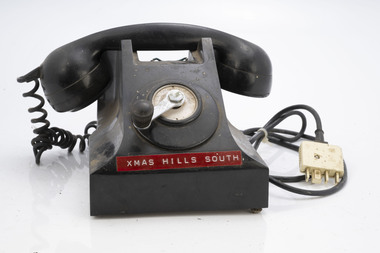
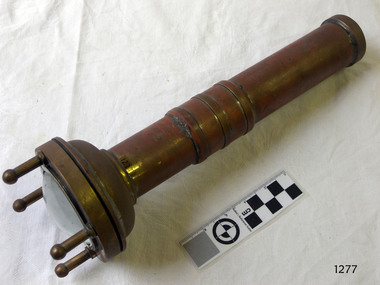
After the 1939 bushfires, the Forests Commission Victoria invested heavily in a radically new communications network. After suffering some inevitable delays due to the war, radio VL3AA switched into full operation in October 1945 proudly beaming out 200 watts across the State. But by today’s standards, the technology was primitive and the reception poor unless the user was on a high point somewhere. The radio signal was "line-of-sight" and bounced between fire towers and relay transmitters across the mountains back to the District offices. The advent of solid-state electronics in the 1960s replaced the more delicate valve sets which enabled greater use of vehicle mounted radios. The Commission continued to research, develop and build new radios at its many workshops around Victoria. The network was supported by a large team of skilled radio technicians. The more secure and versatile State Mobile Radio (SMR) digital trunk system came into operation in about 1995. Upgraded Tait Radios were purchased in 2014 after recommendations of the 2009 Bushfires Royal Commission. But it was the convergence of separate technologies such as 5G mobile phones, high-capacity and light-weight lithium batteries, Wi-Fi, the ever-expanding internet, cloud data storage, digital cameras, GPS, personal organisers and hundreds of supporting Apps into powerful smartphones and tablets which revolutionised bushfire communications from the mid-2000s. Used to communicate to remote fire towers Single wire often run through the bush from FCV district officesFire tower telephone with winderChristmas Hills South Instructions for use around winderbushfire, radios, forests commission victoria (fcv) -
 Department of Energy, Environment and Climate Action
Field telephone - Fire Tower
After the 1939 bushfires, the Forests Commission Victoria invested heavily in a radically new communications network. After suffering some inevitable delays due to the war, radio VL3AA switched into full operation in October 1945 proudly beaming out 200 watts across the State. But by today’s standards, the technology was primitive and the reception poor unless the user was on a high point somewhere. The radio signal was "line-of-sight" and bounced between fire towers and relay transmitters across the mountains back to the District offices. The advent of solid-state electronics in the 1960s replaced the more delicate valve sets which enabled greater use of vehicle mounted radios. The Commission continued to research, develop and build new radios at its many workshops around Victoria. The network was supported by a large team of skilled radio technicians. The more secure and versatile State Mobile Radio (SMR) digital trunk system came into operation in about 1995. Upgraded Tait Radios were purchased in 2014 after recommendations of the 2009 Bushfires Royal Commission. But it was the convergence of separate technologies such as 5G mobile phones, high-capacity and light-weight lithium batteries, Wi-Fi, the ever-expanding internet, cloud data storage, digital cameras, GPS, personal organisers and hundreds of supporting Apps into powerful smartphones and tablets which revolutionised bushfire communications from the mid-2000s. Used to communicate to remote fire towers Single wire often run through the bush from FCV district officesFire tower telephone with winderChristmas Hills South Instructions for use around winderbushfire, radios, forests commission victoria (fcv) -
 Department of Energy, Environment and Climate Action
Remote telephone - Fire Tower
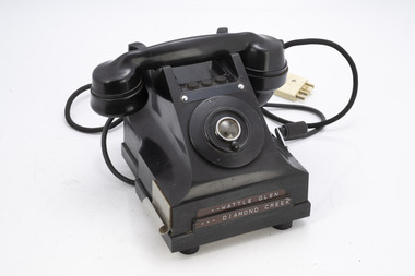
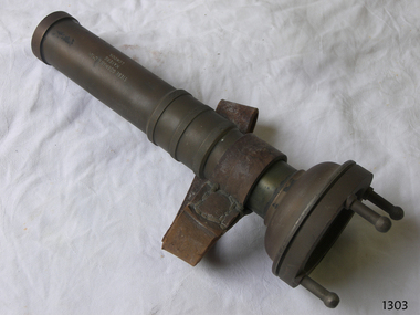
After the 1939 bushfires, the Forests Commission Victoria invested heavily in a radically new communications network. After suffering some inevitable delays due to the war, radio VL3AA switched into full operation in October 1945 proudly beaming out 200 watts across the State. But by today’s standards, the technology was primitive and the reception poor unless the user was on a high point somewhere. The radio signal was "line-of-sight" and bounced between fire towers and relay transmitters across the mountains back to the District offices. The advent of solid-state electronics in the 1960s replaced the more delicate valve sets which enabled greater use of vehicle mounted radios. The Commission continued to research, develop and build new radios at its many workshops around Victoria. The network was supported by a large team of skilled radio technicians. The more secure and versatile State Mobile Radio (SMR) digital trunk system came into operation in about 1995. Upgraded Tait Radios were purchased in 2014 after recommendations of the 2009 Bushfires Royal Commission. But it was the convergence of separate technologies such as 5G mobile phones, high-capacity and light-weight lithium batteries, Wi-Fi, the ever-expanding internet, cloud data storage, digital cameras, GPS, personal organisers and hundreds of supporting Apps into powerful smartphones and tablets which revolutionised bushfire communications from the mid-2000s. Used to communicate to remote fire towers Single wire often run through the bush from FCV district officesFire tower telephone with winderWattle Glen Diamond Creekbushfire, radios, forests commission victoria (fcv) -
 Department of Energy, Environment and Climate Action
Remote telephone - Fire Tower
After the 1939 bushfires, the Forests Commission Victoria invested heavily in a radically new communications network. After suffering some inevitable delays due to the war, radio VL3AA switched into full operation in October 1945 proudly beaming out 200 watts across the State. But by today’s standards, the technology was primitive and the reception poor unless the user was on a high point somewhere. The radio signal was "line-of-sight" and bounced between fire towers and relay transmitters across the mountains back to the District offices. The advent of solid-state electronics in the 1960s replaced the more delicate valve sets which enabled greater use of vehicle mounted radios. The Commission continued to research, develop and build new radios at its many workshops around Victoria. The network was supported by a large team of skilled radio technicians. The more secure and versatile State Mobile Radio (SMR) digital trunk system came into operation in about 1995. Upgraded Tait Radios were purchased in 2014 after recommendations of the 2009 Bushfires Royal Commission. But it was the convergence of separate technologies such as 5G mobile phones, high-capacity and light-weight lithium batteries, Wi-Fi, the ever-expanding internet, cloud data storage, digital cameras, GPS, personal organisers and hundreds of supporting Apps into powerful smartphones and tablets which revolutionised bushfire communications from the mid-2000s. Used to communicate to remote fire towers Single wire often run through the bush from FCV district officesFire tower telephone with winderWattle Glen Diamond Creekbushfire, radios, forests commission victoria (fcv) -
 Department of Energy, Environment and Climate Action
AWA Superheterodyne receiver
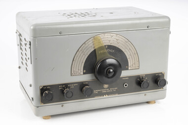
After the 1939 bushfires, the Forests Commission Victoria invested heavily in a radically new communications network. After suffering some inevitable delays due to the war, radio VL3AA switched into full operation in October 1945 proudly beaming out 200 watts across the State. But by today’s standards, the technology was primitive and the reception poor unless the user was on a high point somewhere. The radio signal was "line-of-sight" and bounced between fire towers and relay transmitters across the mountains back to the District offices. The advent of solid-state electronics in the 1960s replaced the more delicate valve sets which enabled greater use of vehicle mounted radios. The Commission continued to research, develop and build new radios at its many workshops around Victoria. The network was supported by a large team of skilled radio technicians. The more secure and versatile State Mobile Radio (SMR) digital trunk system came into operation in about 1995. Upgraded Tait Radios were purchased in 2014 after recommendations of the 2009 Bushfires Royal Commission. But it was the convergence of separate technologies such as 5G mobile phones, high-capacity and light-weight lithium batteries, Wi-Fi, the ever-expanding internet, cloud data storage, digital cameras, GPS, personal organisers and hundreds of supporting Apps into powerful smartphones and tablets which revolutionised bushfire communications from the mid-2000s. AWA ReceiverType IC 9640bushfire, radios, forests commission victoria (fcv) -
 Royal District Nursing Service (now known as Bolton Clarke)
Photograph - Photograph, black and white, c.1965
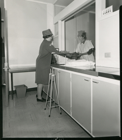
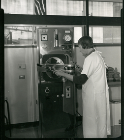
This photograph is taken in the Melbourne District Nursing Service (MDNS) Footscray Centre and shows a Sister receiving sterilized equipment from a Sister in the Autoclave room. The Sister receiving the equipment will use this when giving specific nursing care to a patient in her home.Melbourne District Nursing Service (MDNS), later called Royal District Nursing Service (RDNS), had an Autoclave room in each Centre where Catheter trays, dressing trays, as well as dressing packs and gowns and towels were sterilized for their Trained staff (Sisters) to take to the home when attending to a patient who required specific nursing care. When the Sisters returned to the Centre they cleaned the equipment and set up the trays ready for re-sterilizing. On the right of the black and white photograph is a Melbourne District Nursing Service (MDNS) Sister, wearing a white gown over her grey uniform, with peaks showing, and wearing her grey peaked hat over her short dark hair. She is smiling as she is handing sterilized equipment through the opened sliding window of the sterilizing room. The Sister receiving the equipment is to the left in the next room. She is wearing her grey uniform coat and peaked hat over her short dark curled hair, and is standing against a row of cupboards with their bench top at the level of the sliding window. To her right, a rectangular metal basket sits on the bench top; a white drape is in the basket and another to its right. A four pronged walking stick stands on the floor to her right hand side. At the rear left a small table is against the wall with a small grey square tapering rubbish bin beneath it. The edge of the open door can be seen on the far left. In the foreground some of the cupboards, and part of a wall with an electric switch can be seen.Photographer's stamp. Quote No. GX 6 Handwritten informationmelbourne district nursing service, mdns, royal district nursing service, rdns, rdns equipment, sterilizing, rdns centre -
 Royal District Nursing Service (now known as Bolton Clarke)
Photograph - Photograph, black and white, c.1967
This photograph is taken in the Sterilizing room in the Royal District Nursing Service (RDNS) Footscray Centre. Sister Short is closing the door of the Autoclave to sterilize equipment and dressings which will then be used by a RDNS Sister when she is visiting a patient in the community. Sterilizing of equipment and dressings were carried out at each RDNS Centre. Royal District Nursing Service (RDNS) supplied sterilized equipment, such as ready set up catheter trays and dressing trays, as well as dressing packs for their trained staff (Sisters) to take to the home when attending to specific patient care. When the Sisters returned to the Centre they washed and set up the trays again ready for re-sterilization. Each RDNS Centre had an Autoclave room and equipment and dressings were sterilized each day.Black and white photograph showing Royal District Nursing Service (RDNS), Sister Margaret Short, who has short dark hair, and is wearing a white gown over her uniform, with the grey peaks seen. She is using the Autoclave in the Sterilizing room. The tall rectangular metal sterilizer stands in the centre of the photograph. There are several small dials and a larger square dial on its upper left, with a long encased thermometer in the centre and a large round dial to its right. Below this is the partly open large metal door of the sterilizing section. A thick horizontal metal piece runs from the left side of the sterilizer, across, and attached at the centre, of the door. Sister Short has her left hand on the turning bar attached to the centre section, and her right hand is on the locking section as she closes the door. Below the door are two switches and several small dials. To the left of the sterilizer is a cabinet, and to the right of Sister Short, eight small wrapped dressing packs are on a shelf. At the rear of the photograph the wall goes halfway up, with windows above.Photographer's Stamp. Quote No. GX 12 Handwritten informationroyal district nursing service, rdns, footscray centre, sterilizing, sister margaret short -
 The Beechworth Burke Museum
Postcard, George Rose, c.1945
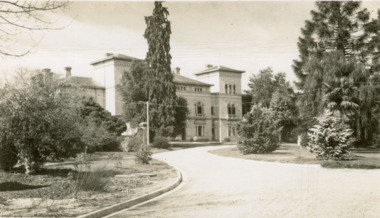
The Rose Stereograph Company first began producing postcards, identified as the 'P' series (like this particular example) in 1913 and continued in this business until 1967 after which they switched to machine manufactured colour postcards printed by an external company. These were produced by Victorian-era photographer George Rose (1861-1942) often reputed as one of the best photographers in Australia during the later 19th Century and early 20th Century. Rose was born in 1861 in Clunes and began his photography business in 1880 when he founded the Rose Stereograph Company. He later switched to producing postcards after stereographs lost popularity in the early 1920s. The Mayday Hills Hospital was one of these locations photographed by George Rose and published as a postcard. Beechworth's Mayday Hills was chosen as the site of Victoria's newest asylum, at the time, due to the landscape and altitude. The hilltop atmosphere and the native fauna, it was argued, would assist in the cure of the patients kept at the hospital (Wood 1985, 122). The positioning of the hospital had a beneficial effect on the rural town. A pamphlet published by James Ingram and Son (1849) reveal that famous landmarks in Beechworth which included the Post Office, Gaol, Courthouse and Asylum "demonstrate the appreciation of Beechworth by the Government not only as as important district center, but also as a site unrivaled as a sanitarium". There were other locations in contention at the time, but ultimately Beechworth was chosen (Craig 2000,33). Prior to the creation of the Asylum in Beechworth, those charged with having mental illnesses or, as it was termed, "insanity" were unable to be properly cared for in the Gaol (which is where they were often sent). John Buckley Castieau wrote, in 1861 for the Ovens and Murray Advertiser, that the Gaol was unable to properly care for those classified then as "insane" but that they would endeavor to treat them above the other inmates (which he notes is not always the case in other establishments). Castieau wrote this in favour of supporting the building of the Mayday Hills Hospital in Beechworth. It was stated that at the time the Mayday Hills Hospital was built, there were 83 prisoners kept in the Gaol who were to be rehoused to the Hospital on the grounds of "insanity". The classification as someone as "insane", in this period of time is a reflection on the inability to cure and understand illnesses of the mind during the mid to late 1800s. Opening on the 24th of October 1867, the Mayday Hills Hospital was originally named the "Ovens Lunatic Asylum", a title which is very much a product of its time. Whilst controversial, changes to the name is part of the history of the Hospital and can provide much insight into the understanding of mental illness throughout history and the use/disuse of this term provides information into the reception/changing opinions of mental illness in society. The Hospital would later become known as the "Mayday Hills Asylum" and/or "Mayday Hills Hospital" with the latter being the most commonly used title. An article in the Ovens and Murray Advertiser notes that on the 7th of March 1865, the foundation stone of the Hospital was laid (it would officially open in 1867) and that it was such a moment of accomplishment and joy for Beechworth that a letter to the editor even suggested that there should be a holiday dedicated to the day the foundation stone as laid. This reveals an extent to which the townspeople of early Beechworth valued the construction of the Hospital in their town. It provided the town with a sense of prestige and honour. At first glance, the remains of the Mayday Hills Hospital in Beechworth, Victoria, inspire tragedy, trauma and beauty. The buildings themselves, with their Italianate style Renaissance architecture designed by J.J. Clark (Craig 2000, 49 & Smith 2016, 203) reflect a bygone period of European and Australian history. The gardens provide a sense of tranquility and beauty. The experience of those within these walls remains a valuable area of study to provide a more complete understanding. This particular hospital is considered the fourth of its like and one of three identified as the largest of their kind. The Mayday Hills Hospital is a sister to the Kew and Ararat Asylums in Melbourne which are both located in relative proximity. Understanding the role of the Mayday Hills Hospital in Beechworth history is integral to understanding the development of the goldfields town, but also for providing important information as to the history of caring for, and the reception of, mental illnesses in Australian and wider European history. Mayday Hills provides a case study which can be researched through oral history, an analysis of the grounds/buildings and through images like this postcard which portray the structure in a highly deliberate manner. Images like this depict the strong façade of the Hospital and provide a glimpse into the tranquility of the gardens. This has been done deliberately to provide a sense of comfort and healing about the building to those looking from the outside. Further research into the importance of the Hospital in Beechworth and it's connection to the town will be supported through images like these kept in the Mayday Hills photo album in the collection of the Burke Museum.Pale sepia toned rectangular postcard printed on matte card.Obverse: THE ROSE SERIES P. 4689 / COPYRIGHT / ADMINISTRATIVE OFFICES, MENTAL HOSPITAL, BEECHWORTH, VIC / Reverse: Published by the Rose Stereograph Co. / Armadale, Victoria / POST CARD / THE "ROSE" SERIES / DE LUXE / A REAL PHOTOGRAPH / PRODUCED IN AUSTRALIA /mayday hills, asylum, mental hospital, hospital, beechworth -
 Melbourne Tram Museum
Document - Folder, William Pollock, "The Melbourne Cable Tramway System", c1940
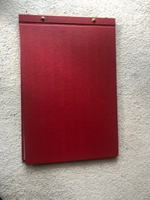
Folder - heavy red covers with two screw sets containing a photocopy of a report by William Pollock, prepared after the closure of the cable tram system titled ""The Melbourne Cable Tramway System". Image numbers listed: Folder – htd4715i1 Inside of folder – htd4715i2.jpg Report –Photocopy of a 14 foolscap sheets, paper titled “The Melbourne Cable Tramway System” by William Pollock, describing the system in detail, listing 26 appendices. Has notes on each Power Station, including a table of opening, closing, power produced and cables, fuel, permanent way (track), cables, underground gear, tunnels, flooding and the grip. Image – htd4714i3.pdf Appendix 1 – Handwritten table “Cost the Melbourne Tramway System” – photocopied special size sheet folded. See image htd4715i4.jpg 2 – Drawing – Typical Power House layout - image htd4715i5.jpg 3 – Drawing – Head of Cable Driver – htd4715i6.jpg 4 – Drawing – Rope Drive – htd4715i7.jpg 5 – Photocopy of a Fuel and Water test sheet for the Esplanade Power House – two sheets – 14/5/1918 – htd4715i8.jpg and htd4715i9.jpg 6 – Section of Cable Tram track – htd4715i10.jpg 7 – Tar Burner used by MTOC 1893 – 1900 - htd4715i11.jpg 8 – Yoke Bracket for line drums – A1 Pulley – htd4715i12.jpg 9 – Tunnel Yoke – htd4715i13.jpg 10 – Elevating Wheel or Pulley with shield plate – htd4715i14.jpg 11 – Curve Pulleys, curve drum and rubbing bar – 2 sheets – htd4715i15.jpg and htd4715i16.jpg 12 – Curve or Conical drum – htd4715i17.jpg 13 – Cable Separating pulley or cone line drum – htd4715i18.jpg 14 – Yoke Pulley or General Pulley – htd4715i19.jpg 15 – Yoke Bracket for Drums – htd4715i20.jpg 16 – Automatic Switch Gear – htd4715i21.jpg 17 – Hand operated switch gear – htd4715i22.jpg 18 – Hand pickup – htd4715i23.jpg 19 & 20 – Photo of bunched strands and damaged cable – htd4715i24 21 – Diagram of Rope – Clarendon St Rope No. 41 – htd4715i25.jpg 22 – Strand Alarm – htd4715i26.jpg 23 – Rope History – two sheets – htd4715i27 and htd4715i28.jpg 24 – Rope Splice – htd4715i29.jpg 25 – Cable Grip – htd4715i30.jpg 26 – Crown Pulley – two sheets – htd4715i30 and htd4715i31trams, tramways, drawings, tramcars, cable trams, trackwork, mto co, reports -
 Kiewa Valley Historical Society
Electric Megger (Insulation Tester) and its case
Megger as the device was called, is in fact its brand name. It is a device that supplies a DC (direct current as per car batteries) voltage to enable testing of electrical apparatus. This particular device produces 250volts DC when the handle is turned vigorously. If an electrical device, such as a kettle or toaster, blew a fuse or tripped a circuit breaker, when switched on, then it must be checked electrically before any more use. Following the repair of the faulty item a megger would be used to check if either of the AC 240volt plugs leads were touching the metal case (earth). The output leads of the megger would be connected with one to the earth (metal case) and the other to each of the power connections in turn. A good megger reading of 50,000 ohms (resistance) would enable the device to be returned to service. A reading of zero ohms resistance would mean that it would again blow a fuse, and was therefore unsafe to use. In the electrical industry e.g. the former State Electricity Commission, a megger would be used to test lots of similar item in sequence. Because of the vigorous job of winding the handle, two persons were often used to save time. One would crank madly whilst the other shifted the leads. This particular megger is of a small voltage, but other meggers are bigger and have a few ranges of DC voltages able to be selected. The optimal megger for large Generating machines was motor driven megger. This was applied to the device being tested for a duration of approximately 30 minutes with reading of the resistance taken at regular intervals.All equipment belonging to the State Electricity Commission of Victoria was labelled with a metal plaque attached to it. The SECV constructed the Kiewa Hydro Electric Scheme in the Upper Kiewa Valley and on the Bogong High Plains. The scheme began in 1938 and finished in 1961 when this megger was used and also possibly later as the SECV remained to maintain and operate the Scheme. This megger is of significance in relation to the advancement of technology.A rectangular box in dark brown bakerlite casing. It has an agent's plaque fixed to the left of the face and on the right is the marker's recessed stamp. In the middle in a transparent window so the level of ohms can be read. The front also has two recessed fixing knobs in black. On one side is a crank handle with a knob that lifts up and is turned vigorously to create the voltage. The back has four recessed screws and four small leather pads. There is a hole on each side to insert wires. There are two copper insulated wires. The SECV Plaque states: State/Electricity Commission/of/Victoria/ Electrical Engineer's Section/ No.1747 The Agent's Plaque states: H. Rowe & Co. Pty Ltd/Melbourne & Sydney/Sole Agents/in Australia for/Evershed & Vignoles Ltd Maker's states: 500 volts/Megger/Regd Trade Mark/Made in England/Patent No/400728electrical meters, electrical equipment, fuses, safety, state electricity commission of victoria, mt beauty, bogong village -
 City of Greater Bendigo - Civic Collection
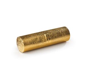
Artwork, other - Gold Chicko Roll, Simplot Australia, 2001
Commemorative object produced by Simplot Food Service and presented to the City of Greater Bendigo on the occasion of the 50th anniversary of the creation of the Chicko Roll by Bendigo born boiler maker, Frank McEncroe. The Chicko Roll has been an Australian icon since the 1960's and 70's. Inspired by the Chinese spring roll and first sold in 1951 as the "Chicken Roll" despite not actually containing chicken. The snack was designed to be easily eaten on the move without a plate or cutlery and is typically deep-fried in vegetable oil. By 1965 the ubiquitous Chicko Roll was sold in every fish and chip shop throughout the country and at the height of their popularity in the 1970s, 40 million Chiko Rolls were being sold Australia-wide each year and more than one million were exported to Japan.(Wikipedia https://en.wikipedia.org/wiki/Chiko_Roll). Advertised with the slogan 'Grab a Chiko', 'Hit the Hot Spot' and 'You Can't Knock the Roll' the marketing around the Chicko Roll was aimed towards the male population with women perched on Harley Davidson's prevocatively preparing to bite into a Chicko Roll. In 2008 with a push towards healthier eating, Chicko Roll reviewed its advertising and although it continues to target young men, it switched to using a 'fun, active' young women, riding a retro pushbike near the beach to improve its image. In 1995 J.R. Simplot, an American company who also own Leggo's, Birds Eye, Edgell and John Wes,t acquired Chicko Roll to sure up their foothold in the Australian market. Life size gold plated chicko roll in a hinged wooden presentation box with red lining. Double sided, printed letter accompanying the object explains its creation and significance.0365.1; CHICKOcity of greater bendigo commerce, mayor acherman -
 Wodonga & District Historical Society Inc
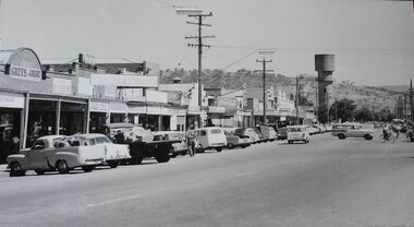
Photograph - High Street Wodonga in the 1950s
This image shows High Street, Wodonga in the late 1950s to early 1960s. The view is taken looking southwards towards the Water Tower at the end of the street. Businesses visible in the image include Currans Shoe Store, Greens Shoe Repair, a barber store, Pat's Ladies Hairdresser and Beauty Parlour, Albury Drycleaners, Jim Costello's, Bye's Butchery, Cafe, Astor Electrical goods and Victorian Producers. It is an enlargement of a Rose Series postcard. This photograph is representative of many images representing High Street, Wodonga as it developed over time. The Rose Series of postcards is a series of postcards of scenes from around Australia and some international ones as well. They were produced by the Rose Stereograph Company, which was the business of Victorian photographer George Rose (1861-1942). In 1880, George, aged 19, founded his business in Victoria, and soon became famous for producing stereographs, or stereo views. His early images included the landing at Anzac Cove, Ned and Dan Kelly’s Armour (taken at trial in 1880), The Duke & Duchess of York and their daughter Princess Elizabeth and Phar Lap winning the Melbourne Cup. When stereographs lost popularity during the 1920s, Rose switched to the production of postcards and decorative cards. He and his team of photographers took thousands of photos of scenery around Victoria and beyond, and the postcards became iconic images of Australian life. The Rose Stereograph Company Collection comprising more than 100,000 items was auctioned by Lloyds in June 2021. This image shows the main street of Wodonga and allows us to trace its development over time.A large photo printed on canvas. It shows High Street Wodonga in the late 1950s, looking southwards towards the water tower.high street wodonga, wodonga businesses, wodonga 1950s -
 Flagstaff Hill Maritime Museum and Village
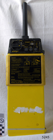
Equipment - EPIRB Transmitter
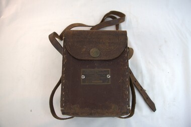
This distress EPIRB unit (Emergency Position Indication Radio Beacon) was found on the beach at Levy's Point, Warrnambool, in December 2000 by a Warrnambool resident. Local police were alerted at the time. This distress signal unit is a world-wide COSPAS/SARSAT, satellite assisted, SAR (Search and Rescue) system for location of distress transmissions emitted by an EPIRB. Offshore cruising vessels must have such a unit as part of its essential safety equipment. This model EPIRB relies on four satellites with orbit times of approximately 100 minutes. Earlier units relied solely on aircraft flying overhead to detect and forward on the EPIRB’s location to Search And Rescue authorities, whereas this new system utilises satellites. An employee from the Lokata firm provided additional information about the Lokata EPIRB units. They had a machined aluminium case with labels that were also made on site. The units could be activated manually or automatically released when a magnetic switch in the case casing was activated. This later model, circa 1983, would have been mounted externally on a vessel's bulkhead in a spring-loaded, stainless-steel protective 'skeleton' mounting, The unit released when the water pressure sensor detected a set time it was under the water, in a similar way that life crafts were released. Each unit was registered to a particular vessel - the vessel's details on this unit are indecipherable. The Lokata Company was established in 1970, designing and manufacturing marine products including communications. The company no longer makes products with the “Lokata” brand. In 2001 Sartech Engineering Ltd. took over the support for the Lokata EPIRB beacons. This emergency location device is a late 20th century invention to help save lives at sea. It adds to the history of maritime life, its risks, the lives lost as sea, and the many inventions aimed as rescuing and saving lives. The local area is notorious for the number of lives lost through shipwreck. It also carries stories of heroic efforts to save lives, and other inventions to help reduce the chance of accidents at sea.EPIRB unit; “Emergency Position Indication Radio Beacon”. A distress communication unit for sending a distress location transmission in an emergency at sea. The EPIRB is a yellow, rectangular box with dials, buttons, indicator lights and instruction. An antenna protrudes from the top of the unit. The EPIRB unit sends a 406P (X) EPIRB, with 406M-Hz frequency, 48-hour duration signal. The maker was LOKATA Ltd in England. Remnants of a white label remain on the side. Circa 1980s."NAME OF VESSEL 'SERVICE IF SELF TEST FAILS' " “LO-KATA” moulded into the body. "406P (X) EPIRB" “Model 406” "Lokata Type No 92408" "UK Type approved to MPT 1278" "Class 2" "Made by Lokata Ltd, Falmouth Cornwall England TR10 8AE"" "LOKATE LTD. New North Road Hainault, Ilford Essex IG6 2UR" "ARMED / SAFE / TRANSMIT / CODE / DISPLAY / SET / wait / pass / fail / TEST" "IDENTIFIER / 1349:24034234N" [some characters may be different] "COUNTRY / DENMARK" "VESSEL IDENTITY / 124 [the rest is indecipherable]flagstaff hill, warrnambool, shipwrecked-coast, flagstaff-hill, flagstaff-hill-maritime-museum, maritime-museum, shipwreck-coast, flagstaff-hill-maritime-village, emergency position indicating radio beacon, epirb, lokata ltd, marine safety equipment, satellite transmitting beacon, safety equipment, distress signal, life saving, safety at sea, shipwreck location, lo-kata, falmouth, emergency, beacon, radio signal, communication, marine equipment -
 Federation University Historical Collection
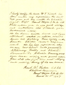
Letter - Correspondence, Norman F. White, Correspondence on Mount Morgan Gold-mining Company, Limited Letterhead, 1907, 22/03/1907
Typed letter on Mount Morgan Gold-mining Company, Limited Letterhead relating to staffmember W. Gildard who worked in the Electrical Department at Mount Morgan. The letter is signed by Norman F. White..1) I hereby certify the Bearer Mr W. Gildard has been under my supervision this last two years and six months in Electric Light Dept Mount Morgan G.M.Co. Ltd While under me he was quick steady and industrious also possessed good mechanical ideas. He has been switch board and Dynamo attendant worked on outside circuits series are Lighting Mine Lighting under Ground Electric Bells and Telephone work. He has had experience also on our new plant turbo generators Stationary Motors and Electric Locomotives Electric Tramway Work over head wiring and ground return you will also find him most obliging and willing. Leaving of his own accord. Frank McFarlane A.G.E.E. Electric Foreman Mount Morgan G.M. Co. Ltd march 21st 1907ballarat school of mines, mount morgan gold-mining company, mount morgan, norman f. white, electricity, w. gildard, letterhead -
 Flagstaff Hill Maritime Museum and Village
Tool - Torch, 1935-1960
Diver's Submarine Electric Torches were first developed to give illumination for close examination work. They have to be self-contained, the older ones are powered by an accumulator type battery which could be recharged. Some models were fitted with a switch to turn the light off saving on the battery power. The lens is of a convex type and magnifies the light. Sometimes there was a protective grill across the glass or prongs to protect the glass from an impact. When fully charged the battery would last about seven hours. Torches are made from non-ferrous metal so as not to corrode in their watery environment. Siebe Gorman & Co Ltd has been producing hand-held, battery-powered, submarine electric torches for divers and the Ministry of Defence (MOD) since the 1920s. In 1961, the famous diving manufacturer C.E. Heinke merged with Siebe Gorman, and for a short while, torches were made with the combined 'Siebe Heinke' inscription. However, this linked inscription was later dropped, with a return to the Siebe Gorman name tag. Date of manufacture for these torches can be determined by their Admiralty Pattern (AP) number that was used to identify a particular item and were for naval stores use. Before NATO stock coding became more widely used, earlier MOD torches often have a simple four-digit group of AP numbers such as AP4456 or AP4458. In 1975 Siebe Gorman moved from their Neptune Works at Chessington in Surrey to a new location at Cwmbran in Wales and by this time their manufacture of diving equipment had declined. (For additional historic company information on Siebe & Gorman see notes section this document.)The item is significant as it gives us a snapshot into marine history and the development of diving equipment generally, especially that used for salvage operations before and during WW2. The company that made the torch Siebe Gorman was a leading inventor, developer and innovator of marine equipment with its early developments in helmets, compressors and other diving equipment. Items that are today eagerly sought after for maritime collections around the world. The items that have been donated to the Flagstaff Hill collection give us an insight as to how divers operated and the dangers they faced doing a very necessary and dangerous job.Diver's Torch brass with heavy glass screw on piece with four lugs attached contact spring inside. Leather hand strap missing."Siebe Gorman and Co Ltd, Makers, London." Has "A.P.4458" inscribed on front above glassflagstaff hill, warrnambool, shipwrecked coast, flagstaff hill maritime museum, maritime museum, shipwreck coast, flagstaff hill maritime village, great ocean road, siebe, gorman, diver's torch, torch, diver, diving accessories -
 Flagstaff Hill Maritime Museum and Village
Tool - Torch, 1935-1960
Diver's Submarine Electric Torches were first developed to give illumination for close examination work. They have to be self-contained, the older ones are powered by an accumulator type battery which could be recharged. Some models were fitted with a switch to turn the light off saving on the battery power. The lens is of a convex type and magnifies the light. Sometimes there was a protective grill across the glass or prongs to protect the glass from an impact. When fully charged the battery would last about seven hours. Torches are made from non-ferrous metal so as not to corrode in their watery environment. Siebe Gorman & Co Ltd has been producing hand-held, battery-powered, submarine electric torches for divers and the Ministry of Defence (MOD) since the 1920s. In 1961, the famous diving manufacturer C.E. Heinke merged with Siebe Gorman, and for a short while, torches were made with the combined 'Siebe Heinke' inscription. However, this linked inscription was later dropped, with a return to the Siebe Gorman name tag. Date of manufacture for these torches can be determined by their Admiralty Pattern (AP) number that was used to identify a particular item and were for naval stores use. Before NATO stock coding became more widely used, earlier MOD torches often have a simple four-digit group of AP numbers such as AP4456 or AP4458. In 1975 Siebe Gorman moved from their Neptune Works at Chessington in Surrey to a new location at Cwmbran in Wales and by this time their manufacture of diving equipment had declined. (For additional historic company information on Siebe & Gorman see notes section this document.)The item is significant as it gives us a snapshot into marine history and the development of diving equipment generally, especially that used for salvage operations before and during WW2. The company that made the torch Siebe Gorman was a leading inventor, developer and innovator of marine equipment with its early developments in helmets, compressors and other diving equipment. Items that are today eagerly sought after for maritime collections around the world. The items that have been donated to the Flagstaff Hill collection give us an insight as to how divers operated and the dangers they faced doing a very necessary and dangerous job.Divers torch, brass with glass lens , screw on piece with three lugs attached. Leather wrist strap attached & loose contact spring inside."Siebe Gorman and Co Ltd, Makers, London." Has A.P.4456 stamped on front faceflagstaff hill, warrnambool, shipwrecked-coast, flagstaff-hill, flagstaff-hill-maritime-museum, maritime-museum, shipwreck-coast, flagstaff-hill-maritime-village -
 Ballarat Tramway Museum
Photograph - Digital image Set of 10, 1971
Yields information about Ballarat Tramways and trams prior to the closure of the tramway system.Set of 10 digital images of Ballarat trams prior to closure, scanned from original slides by Stuart Lodington, 1971 prior to closure of the system. .1 - No. 17 at the City Centre, Sturt St, south side, with Gardens via Sturt St on destination roll. Can see the ESCo switch box in the back and the stop and section sign on the adjacent pole. .2 - No. 26 at Sebastopol terminus alongside the Royal Mail Hotel. The tram has yet to turn the pole or the destination roll. Note the Bus Stop sign on the pole, just prior to closure. .3 - ditto .4 - No. 27 and 30 crossing in Skipton St at the Bell St loop (see also btm4975i3) .5 - No. 32, Gardens, about to enter the Carlton St loop, with Lake Wendouree in background, Wendouree Parade. .6 - No. 32 at Depot junction, good photo of depot trackwork entry area. .7 - No. 21, Wendouree Parade, Gardens area, north bound, showing Gardens via Sturt. .8 - No. 12, inbound on Sturt St west at a tram stop. Has destination of Mt. Pleasant. .9 - No. 27 at Lydiard St north terminus with the shelter in the background. .10 - No. 21 at Gardens Loop, tram has destination of Mt. Pleasant. Crews sitting in the saloon.trams, tramways, ballarat, sturt st, sebastopol, drummond st sth, wendouree parade, carlton st, depot, depot junction, trackwork, gardens, sturt st west, crews, tram 17, tram 26, tram 27, tram 32, tram 21, tram 12 -
 Ballarat Tramway Museum
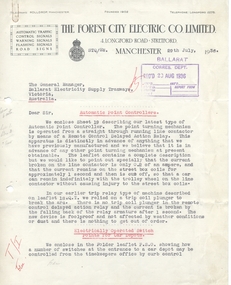
Pamphlet, The Forest City Electric Co. Limited England, "Forest City" products, 1936
Yields information about the equipment offered to Ballarat at the time of the determining what type of signals to put in to improve safety on the system, following the take over by the SEC of the tramways. Gives details about other tramway equipment available on the market place.A set of documents under cover of a Forest City letter dated 29/7/1936 to the General Manager Ballarat, typed in black and red ink. Has a date received stamp of 20 August 1936. Contains the following items. 4911.1 - Letter from "The Forest City Electric Co. Limited" to ESCo re Point controllers, tramway signals and warning signs, dated 29/7/1936 - 2 pages 4911.2 - Collins Patent Automatic Point Turner - sheet 19 - 4 pages - sheet 19, two copies 4911.2a - ditto, sheet 18 QT - four pages 4911.3 - Electrically operated Point switches, overhead frogs and signals for tramcar depots. - four pages 4911.4 - Automatic Tramway Signals - five pages - sheet ATS1 4911.5 - Universal Insulator - Sheet 17 - 2 pages 4911.6 - Porcelain hangers - sheet 15/1 - 2 pages 4911.7 - Porcelain insulators for cap and cone suspensions - page 11, 1 page. 4911.8 - Motor Bus and Tramcar Stage and Fare Signs in Cast Aluminium - sheet MD2 - 1 page 4911.9 - Flashers and Spellers - Sheet F1 - 2 pages 4911.10 - Forest City Relays - 2 pages 4911.11 - Traffic light - 1 page, sheet 2A Note the letter the price of the non car counting signals is 20 pounds, including freight.On letter notes in margins and margin on page 2 against tramway signals, marked in red. On rear of page 2 is a pencil sketch.trams, tramways, signals, overhead, traffic lights, points -
 Ballarat Tramway Museum
Book, British Engineering Standards Association, "Electrical Machinery excluding motors for traction purposes", 1927-1939
.1 - Book - 56 pages + grey covers, side stapled, issued by the British Engineering Standards Committee "Electrical Machinery excluding motors for traction purposes", No. 72-1917, September 1917. Has "Commonwealth Engineer" label along the bottom edge. .2 - Book 28 pages - light grey covers, side stapled, issued by the British Engineering Standards Association, "Insulating oils for use in Transformers, oil switches and circuit breakers" No. 148-1923, April 1923. Has a Tait Book Co. stamp along the bottom edge and ESCo date stamp 1 Oct. 1925. Printed by Gaylard & Sons London. .3 - Book 72 pages - light grey covers, side stapled, issued by the British Engineering Standards Association, "Tungsten Filament Electric Lamps" No. 161-1925, August 1927. Has a Tait Book Co. stamp along the bottom edge and ESCo date stamp 15 Feb. 1928. Printed by Waterlow & Sons London. .4 - Book 48 pages - light grey covers, side stapled, issued by the British Standards Institution, "Metal Sheathed paper insulated plain annealed copper conductors for electricity supply including voltage tests" No.1 48-1933, March 1933. Has a Tait Book Co. stamp along the bottom edge and ESCo date stamp 15 Feb. 1928. Printed by Waterlow & Sons London. trams, tramways, power station, standards, materials, electrical systems -
 Royal District Nursing Service (now known as Bolton Clarke)
Photograph - Photograph, black and white, Barry Sutton, c.1970
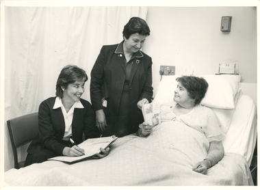
This photograph shows Royal District Nursing Service (RDNS) Sister (Sr.) Moira Coates doing Liaison work at St. Vincent's Hospital in Melbourne. Miss C. Healy is St. Vincent's Home Care Supervisor and she and Sr. Coates are discussing plans with Miss E. Monks for the future care she requires following her discharge from hospital. Sr. Coates is wearing the RDNS uniform of a royal blue dress with white piping around the peaks of the collar. An RDNS logo is on its upper left. She is wearing a darker blue jacket.Liaison had occurred between Doctors and the the Trained nurses (Nurses) of the Melbourne District Nursing Society (MDNS), from its inception in 1885. This increased when Midwifery was introduced in August 1893 with close liaising with the Women’s Hospital. As District nursing grew it was recognized that closer liaising between many Public Hospitals would be beneficial, for not only the MDNS, later called Royal District Nursing Service (RDNS), Trained nurses (Sisters), but also for the patients and the hospitals. In August 1964 a Liaison Officer commenced at the Alfred Hospital. This soon increased to Liaison Officers working full time at several Public Hospitals. They facilitated the smooth transition from hospital to home for many patients who required ongoing nursing care. Liaison Sisters regularly attended discharge planning meetings, interviewed prospective patients, co-ordinated discharge and booked the first visit by the visiting RDNS Sister. At the time of a patient’s discharge, the Liaison Sister forwarded information on their diagnosis and instructions regarding the care required at home to the appropriate RDNS Centre, and in turn the attending District Sister wrote a report of progress and any queries to the Hospital Doctor, via the Liaison Sister, at the time the patient was attending outpatients. Any new instructions were then sent back to the District Sister. Liaising also occurred between District Sisters and Doctors when patients were referred by General Practitioners and did not attend a hospital.In the left foreground of this black and white photograph is Miss C. Healy who has collar length dark hair and is wearing a hospital uniform dark cardigan over a white blouse and dark skirt. She is sitting on a kitchen style chair and has an open folder; a pen in her right hand is poised over a white sheet of paper. She is smiling and looking to her left at Miss E. Monks who is resting in a bed in front of her. Standing to her right, and at the head of the bed, is RDNS Sister Moira Coates who has short dark hair. and is wearing a dark jacket over a dark colour dress with white piping on the collar peaks. Her identity card is clipped on the right hand pocket. She is smiling at Miss Monks and has her left hand on an RDNS leaflet which Miss Monks is holding. To her right is Miss Monk who has short dark hair and wearing a light coloured nightdress. She sitting up supported against pillows on a hospital bed which has the top section raised. She is looking at the RDNS folded leaflet; two photographs and writing can be seen on the front cover. White bedclothes cover most of Miss Monks body. Drawn curtains are seen in the left rear of the photograph and some switches and a name card are seen behind the bed. Barry Sutton. LJ93 and namesrdns, royal district nursing service, rdns liaison, rdns uniform, sister moira coates, miss c. healy, miss e. monks -
 Ballarat Tramway Museum
Book, Australian Commonwealth Engineering Standards Association, "Electrical Performance of Large Electric Generators and Motors - Continuous Maximum Rating", "Pressboard for Electrical Purposes", "Hard Drawn copper stranded circular conductors for overhead power transmission purposes", "for Indicating Ammeters, Voltmeters, wattmeters, frequency and power factor meters", "Instrument Transformers", "Liquid Starters for Electric Motors", "Star Delta switch starters for Electric Motors", "Multiple switch starters for Electric Motors", 1926-1933
.1 - Book - 56 pages + grey covers, side stapled, issued by the Australian Commonwealth Engineering Standards Association, Tentative Australian Standard - "Electrical Performance of Large Electric Generators and Motors - Continuous Maximum Rating" - C36-1927, May 1927 with a green label dated September 1932 advised that the tentative standard has been endorsed as a Standard with amendment. .2 - Book - 48 pages + grey covers, side stapled, issued by the Australian Commonwealth Engineering Standards Association, Tentative Australian Standard - "Electrical Performance of Alternators of the Steam Driven Type" - C38-1927 - December 1927 with a green label dated September 1932 advised that the tentative standard has been endorsed as a Standard with amendment. .3 - Book - 32 pages + grey covers, side stapled, issued by the Australian Commonwealth Engineering Standards Association, Tentative Australian Standard - "Electricity Meters" C39-1927, August 1927. .4 - Book - 28 pages + grey covers, side stapled, issued by the Australian Commonwealth Engineering Standards Association, Tentative Australian Standard - "Pressboard for Electrical Purposes" - C40-1927, January 1927. .5 - Book - 24 pages + grey covers, side stapled, issued by the Australian Commonwealth Engineering Standards Association, Tentative Australian Standard - "Hard Drawn copper stranded circular conductors for overhead power transmission purposes" C41-1930, August 1927, with a green label dated October 1932 advised that the tentative standard has been endorsed as a Standard with amendment. .6 - Book - 48 pages + grey covers, side stapled, issued by the Australian Commonwealth Engineering Standards Association, Tentative Australian Standard "for Indicating Ammeters, Voltmeters, wattmeters, frequency and power factor meters" - C42-1927 - December 1927, with a green label dated October 1932 advised that the tentative standard has been endorsed as a Standard with amendment. .7 - Book - 32 pages + grey covers, side stapled, issued by the Australian Commonwealth Engineering Standards Association, Tentative Australian Standard - "Instrument Transformers" - C45-1928, June 1928. .8 - Book - 28 pages + grey covers, side stapled, issued by the Australian Commonwealth Engineering Standards Association, Australian Standard "Liquid Starters for Electric Motors" C46-1927, December 1927. .9 - Book - 20 pages + grey covers, side stapled, issued by the Australian Commonwealth Engineering Standards Association, Australian Standard "Star Delta switch starters for Electric Motors" C47-1927, December 1927. .10 - Book - 24 pages + grey covers, side stapled, issued by the Australian Commonwealth Engineering Standards Association, Australian Standard "Multiple switch starters for Electric Motors" C48-1927, December 1927. On top right hand corner has the date stamp of the "The Electric Supply Co. of Victoria Ltd Ballarat" trams, tramways, power station, standards, materials, electrical systems -
 Flagstaff Hill Maritime Museum and Village
Domestic object - Sewing Machine, Early 20th century
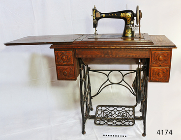
Ward Brothers (George and Samuel) registered a company (Australian Sewing Machines Limited Pty Ltd) with the head office address in Errol St, North Melbourne, and Prahan. The earliest newspaper advertisement for this company was in 1897. Around this time the Ward Brothers first imported sewing machines from England and Wertheim placed their decal on them and mounted them in their own Australian made cabinets. David Ward later imported machines from Beisolt & Locke in Germany and registered name A.N.A. (All Native Australian), his shop was in Collingwood Melbourne. Some of these machines had Ward Brothers decals on them as well. The three brothers sold under the same name as Ward Brothers. The early Ward Brothers logo had a map of Australia with a picture of all three brothers on it. In 1911 all three of the Ward Brothers decided to share a stall in the yearly Melbourne exhibition. The A.N.A was the machine that got rave reviews. It was at this time that the Australian Sewing Machine Company Pty Ltd decided to add the A.N.A logo to their logo to cash in on the new found celebrity status that the A.N.A has gained. To cut a long story short. David Ward took his brothers to court to prevent this from happening. This was a long drawn out affair that took quite a few years. The settlement was decided out of court and nothing was disclosed of the deal that was made. David seemed to have left the scene, then the remaining Ward Brothers and A.N.A. combined and then became “Wardana”. There are many Ward Brothers sewing machines in displays, they originated from Japan, England, America, and Germany. It seems that where ever they got the best deal for sewing machines or parts is the direction they went. This is where the Bendigo sewing machine company came into the picture. All imported sewing machines into Australia drew a government tax. Bendigo Cording's Traction Company was given proposed two-pound tariff protection that gave the company a significant price advantage for its machines. As a result, the Ward Brothers purchased a huge number of Bendigo shares to get cheaper machines for their sewing machine cabinets. Ward Brothers then placed one of their company officials on the Board of “Bendigo Sewing Machines Limited” and the rest is history. Ward Brothers had shops Australian wide and in most of the major country towns. History for “Bendigo Sewing Machines Limited” Cordings Traction Company owners (H. Keck MLC, W. Wallace, and W. Ewing) operated their business out of the former W. Webb & Co. building in Queen St. Bendigo. Around 1923-1924 they decided to switch from traction engines to manufacturing sewing machines. The actual date is not known but that year's financial report made note of both Cordings and Bendigo Sewing Machines Limited. The switch was made with the government of the day agreeing to a tariff of two pounds per head for every machine head made completely in Australia. The change from traction engines to sewing machines went well. Government representatives visited the factory in Bendigo to inspect and ensure that the sewing machines were Australian made as a result they agreed on granting the two-pound tariff to the company. After the first 12 months, they built 30, the following 12 months the company had produced 1500 machines probably due to the involvement of the Ward brothers. However, the government proposed a new condition to the tariff agreement which was that the company must produce 20% of Australia's requirements for sewing machines. In 1924 after having had produced 1500 machines resulting in reaching their financial limit for tariff support. According to the government, the requirement was 15,000 machines for the next year had to be produced to qualify for the tariff. The company had already reached its production limit and unfortunately folded. There were several attempts to regain government assistance to save this new industry but it was to no avail. Even a promise to open another factory in Sydney was offered but unfortunately wasn't accepted. An item fabricated in Australia from a majority of imported parts from either Germany, America or England giving a snapshot into the early manufacturing industries that were operating at the time of Federation. Sewing machine, treadle, in timber cabinet. Branded Ward Bros, A.N.A., Australian Sewing Machine Coy. Decorative carved timber cabinet, hinged, fold-out laminated timber top and five drawers; two small on each side with handles and one long, shallow, between side drawers without handle. Thread is on bobbin in a rocket shuttle (both in good condition) plus spare empty shuttle (rusty). Brass ‘Half Yard’ ruler inlaid across front, measuring scale in inches and centimetres. Two metal shuttle cover plates (or throat plate / slide plate); front one is impressed with a gauge for needle and thread. Gold trim and decals on flatbed and machine front and back, serial number under shuttle cover, brand on decals and on round metal plate on back of machine. Front right of machine has a bobbin winder. Treadle belt shows signs of wear and laminate on timber machine cover is peeling slightly.Decal coat of arms on right front of machine: kangaroo on left, man with broad-brim hat, holding pick-axe on right, in centre, top “SEWING MACHINE / THE / A. N. A.” then below it, the rising sun, then below that is state of Victoria shield with the Southern Cross constellation. Wheat sheaves around edge on left and flowering plant on right. Gold ribbon banner at bottom with script “WARD BROS.“ Decal of map of Australia on flatbed of machine. States and capital cities are marked and named (no northern territory), portrait of two men. In centre of map are interwoven letters “A. N. A.” and written in script “WARD BROS.” Decal across front of machine body has large, decorated gold lettering “A. N. A.” Decal across the top of machine “THE AUSTRALIAN SEWING MACHINE COY. PTY. Ltd.” Steel shuttle cover at front has an impressed gage listing cotton and needle sizes and number of stitches. Brass disc on back of machine “A. N. A.” in centre. Brass ruler across front of machine has carved or pressed words in the timber. In centre “INCHES” above ruler and “CENTIMETRES” below ruler, and on right above ruler is “HALF YARD” Decal across back of machine’s body “A.N. A. / MADE IN U.S.A.” Stamped into metal under shuttle cover is “219415” (2 and 5 are partially there, first 1 could instead be a 7) flagstaff hill, warrnambool, shipwrecked coast, flagstaff hill maritime museum, maritime museum, shipwreck coast, flagstaff hill maritime village, great ocean road, ward bros., australian sewing machine co., a.n.a., treadle sewing machine, rocket shuttle sewing machine, home industry, clothing, wardana, australian sewing machine company, all native australian, dressmaking, clothing manufacturer -
 Department of Energy, Environment and Climate Action
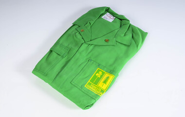
Protective Bushfire overalls
At the time of the 1982-83 bushfire season FCV firefighters wore either navy blue issue overalls or their own clothing, generally a checked flannel shirt and jeans. Uncomfortable safety boots and hardhats were issued. The CFA had switched from white overalls to their distinctive yellow kit by 1983. In about 1980, in a far-sighted corporate move for the time, Alan Threader, who was the Chairman of the FCV, established a departmental safety committee, which he personally chaired. The Committee, among other things, wanted to upgrade fire safety clothing. Alan also initiated a radical colour idea after a work trip to the UK in about 1981 and brought home a small sample swatch. Alan believed that the now distinctive bright yellow-green was a good colour contrast to the Victorian bush which is a blue-green hue. Trevor Brown from Stores Branch scored the task to make the change and letters were sent to the UK seeking information about the pigment. The FCV worked with the Commonwealth Dyers Association and Cushen Clothing to replicate the shade on cotton drill, which presented darker when it was treated with the flame-retardant chemical, Proban. The first of the new Kermit Suits were rolled-out in late 1984, and the stylish colour was initially registered and patented to the Department. But it's also fair to say that the new gaudy shade of apparel wasn’t universally popular with staff. The lime green overalls were an Australian first, and forest agencies in other states followed a few years later. In the early 1990s, armed with a pair of dressmaker’s scissors, the baggy one-piece Kermit boilersuits were tailored by Peter Billing from Fire Protection Branch and Trevor Brown in conjunction with the family-owned business, Top Level Workwear, which saw numerous enhancements and prototypes. The two-piece Kermit suits were available in the late 1990s after many years of argy-bargy and complaints from field firefighters. Protective overalls Two types - early FCV (c 1983) and later CNR (1992) forests commission victoria (fcv), protective clothing, safety equipment -
 Federation University Historical Collection
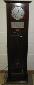
Object, Synchronome Co. Ltd, Synchronome Frequency Checking Master Clock No. 2191, c1930
Information from Norman F. Dalton: Ballarat had a reticulated DC supply in the early part of last century and in 1905 had sufficient generating capacity to enable the trams to be changed from horse drawn to DC electricity. The use of electricity increased with the main power station located on Wendouree Parade, near Webster Street, under the ownership of The Electric Supply Company of Victoria. AC generating plant was installed in 1925 and conversion to AC proceeded. In 1934 the company was taken over by the State Electricity Commission Victoria (SECV) and more AC generation was installed and the changeover of customers was accelerated. This is around the time that the Synchronome Frequency Checking Mast Clock was installed at the Wendouree Parade Power Station. The SECV Annual Report of 1921 states: ::Section 11 of the act directed the COmmission to enquire into the question of securing the adoption of such standards of plant and equipment of a system, frequency and pressure for the generation and distribution of electricity as will admit of the efficient interconnection of undertakings throughout the State. In 1934 when the SECV took over the Ballarat operations the question of linking with the State grid had been a planned operation for some years but due to financial considerations had hindered it and in fact would continue to do so for a further 10 years. So while the need for close frequency control for interconnection was hardly an issue, the need to keep electric clocks correct was important, particularly as this item was a frequent sales point to cover the inconvenience and sometimes expense of converting from DC to AC. The clock is a very accurate pendulum clock with provision for varying effective length during operation for precise time regulation. There are two normal time dials and one is controlled by the pendulum and the other is operated by the system frequency. When the clock was in use it was installed by the MEter and Tests Laboratory and the time was checked daily by radio time signals. The two dials were repeated in the operators control panel in the Power Station. A maximum deviation between the two dials was set in the operating instructions (eg 5 seconds) and the operator would correct this when necessary by remote manual alteration of the turbine governor set point. The clock was used to drive and regulate a system of "slave" clocks which were used to display the time in various locations around the power station. A slave clock is a simple clock which is driven by a small electric motor, its accuracy is regulated by the master clock every 30 seconds to ensure that it and all the other slave clocks in the station are on exactly the right time; slave clocks were placed in various locations, from common rooms to workshops. A master clock could potentially run thousands of slave clocks at one plant. The clock also contains a rectifier. A rectifier is a device that is used to convert AC power to more stable DC current.Two clocks in a timber case. Both are electric, one is powered by the main pendulum mechanism, the other is a self contained electric clock. The main mechanism is of the gravity arm and roller type, which sends an impulse to the slave clocks every 30 seconds. The This Synchronome Frequency Checking Master Clock was used at the Ballarat Power Station. Below the main section of the case is a smaller cabinet containing a rectifier to provide consistent DC power for the clock. The rectifier was made by the Victorian company Hilco, which was located in Burwood. There is a high chance this is not the original rectifier from this clock as there appears to be brackets to hold a larger device in the space the rectifier occupies.Front below main clock face on front of case: "Patented Sychronome Brisbane" Lower left-hand clock face: "Frequency time" Lower right-hand clock face: "Standard Seconds" Synchronous electric clock mechanism on door (Frequency time clock): >200/250 V. 50~ >"Synchronomains" Made in England >Direction indicator for clock starting switch >"To start move lever in direction of arrow and release" >"Patent applied for" Mechanism for "standard seconds" clock: >"English Made" >"Patented" >Serial number "321" >0 above right-hand pillar on front-plate Mechanism for "standard seconds" clock: >"English Made" >"Patented" >Serial number "321" >0 above right-hand pillar on front-plate Mechanism for main clock face: >"English Made" >"Patented" >Serial number "8751" >0 above right-hand pillar on front-plate Inside case, back panel, top enamel plate: >Seconds Battery + Pos. > Battery Common or - Neg. >1/2 min dials Inside case, back panel, bottom enamel plate: external seconds dial Inside case, right hand side, electrical knobs: two switches, both "A.C. mains" Pendulum rod, below suspension spring: Serial number (?) 0000005 Rectifier in bottom cabinet: >"Hilco Rectifier" >"A.C. Volts 230/240" >"Model 1060/S" >"A.C. Amperes" >"Serial No. 1060/S >"Phases 1" >"D.C. Volts 6" >"C.P.S. 50" >"D.C. Amperes 1" >"Made in Australia by Hilco Transformers McIntyre St., Burwood, Victoria." Bakelite electrical plug: makers mark Lower cabinet, RH side panel, pressed tin plate: "AC" (upside down) Brass speed adjustment, outer right RH side: "S" and "F" Ivory and wood pendulum beat ruler: >Ruler, with 0 in centre and numbers 1-5 in ascending order from centre on left and right. > "Synchronome Patent." Steel plate, back panel, inside case, right hand side: >N R A" (descending) >"2191" serial number/part number Face of main clock: "Synchronome Electric" synchronome frequency checking master clock, electricity, state electricity commission, wendouree parade power station, secv, clock, time, pendulum, electric supply company of victoria, norman f. dalton, ballarat power station, rectifier, slave clock -
 Ballarat Tramway Museum
Document - Folder with papers, Robert Ashley, "Ballarat SEC History", 1989
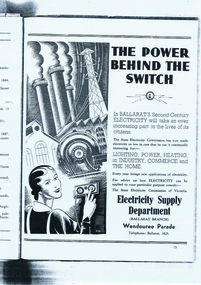
Samizone flat file, made from manila card with blue printing for file details and a Dymo machine label on the spine (red background with white printing) titled "Ballarat SEC History". On inside of folder is a "Post It" note with handwriting "Robert Ashley Ex Employee" in blue ink. Contained within folder is" 1. "Ballarat, Electricity and the State Electricity Commission" photocopied from an original. Has typed under the heading over white out correction fluid "Notes - Draft notes prepared by Robert W. P. Ashley 1989." The paper gives the history of power supply in Ballarat, including street lighting, ESCo, AC and DC power supplies, the takeover by the SEC, Ballarat A and B power stations, a copy of an advertisement for the SEC in Ballarat. (See btm1701i3.jpg) titled "The Power Behind the Switch" 2. Paper by A. D. Senior, titled "Electricity Supply in Ballarat" - see Reg. Item No. 1700. (see btm1700i.pdf) 3. Photocopied onto foolscap paper of an extract from possibly a large report on power supply in Victoria. Pages 155 to 158. Reports on the history of the power supply system in Ballarat until the takeover of ESCo by the SEC. Further details are referred to another section of the Report on the SEC itself. On page 158 are details of Beaufort Council operated supply and the start of notes on Beechworth. (see btm1701i2.pdf) Images of files added 6-8-15 For an image of the advert itself see btm1701i3.pdfSee notes above.trams, tramways, secv, power supply, esco, beaufort -
 Melbourne Tram Museum
Document - Folder with papers, Melbourne & Metropolitan Tramways Board (MMTB), "Notices to Staff", 1924 - 1944
Light grey card folder manufactured by the Roneo Printing Works of Rumford England with the file title "Fire Switches, glued to the top of the folder on the inside back cover. Contains many memos from the MMTB Traffic Managers, Depot Managers about the arrangements for the visit of the Royal Highnesses the Duke and Duchess of York in April 1927. Also contains memo re cable tram arrangements for this event from Port Melbourne depot, arrangements for Christmas holidays and other holidays from about 1924 to 1944, including a map of the procession and printed programs by the Government Printer. Documents either typed or hand written. Other documents include (Sample only): Camberwell extra for December 1944 Shopping Week Memos re traffic arrangements and shunting of trams for the 8 hour day procession Tables for Cable car operations from Port Melbourne depot 5/7/1925 Handwritten car timetables Costs associated with the royal visit Proposed service arrangements for Coburg Lines Christmas and New Year 1929 Cuttings regarding shopping hours for 1929-1930 Football posters - special trams - 1931 and 1932 All Night services - destination rolls to specific bogie trams Memos regarding cancelling of leave in Dec. 1941 Memos regarding services to Fisherman's bend and factory hours - 1941 - 42 Holiday loading returns for Southern System - 1941 Memo re timing of trams from city terminus account 3KZ Christmas Eve Choral festivaltrams, tramways, mmtb, port melbourne depot, notices and information, cable trams, holiday arrangements, royal visit, timetables, world war 2, football, all night services -
 Flagstaff Hill Maritime Museum and Village
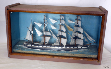
Craft - Ship Model, Loch Torridon, Early 20th century
The Loch Torridon was built in response to the need for a large cargo-carrying ship in the 1870s becoming famous for being one of the most per4fect four-masted barques ever built. She was built for the Loch Line in 1880 by Messrs. Barclay, Curle, and Co. Her measurements were 287 feet in length and 42 feet in beam, and 24 feet depth of hold. She was well sparred and her sail plan was so perfectly balanced that she was a very handy ship, easy on her helm, which was not a common virtue amongst large four-masted ships of her day. Her sails were interchangeable on all three masts, which was common in the last days of sail for both economical and practical purposes. The Loch Torridon was considered one of the most graceful and elegant ships ever launched from the Glasgow shipyards. The first master was Captain Pinder, the first cargo was bound for Melbourne Australia, after which she went on to Calcutta with a cargo of horses. On August the 22nd 1882 with a cargo of Jute onboard loaded in Calcutta the Loch Torridon ran into a storm. Sailing in heavy seas the captain, the second mate also the man at the wheel, and a boy was washed overboard with the first mate just escaping the same fate. Captain Pinder and the crew members could not be rescued and were never seen again with the first mate having to bring the ship home. The next Captain was Robert Pattman who was regarded as a fine navigator and seaman who sailed the Loch Torridon for the next twenty-six years and nine months. He had made 25 voyages around the world during this time without any serious mishap. In 1909 Captain Pattman resigned his command of the ship to switch to a steam vessel but unfortunately was injured on his first voyage and had to be landed at Falmouth, he dies of his injuries shortly afterwards. The Loch Torridon kept on sailing until 1915 after having been sold to a Russian company two years earlier. Near the end of January 1915, the ship sprang a leak of the west coast of Ireland and was abandoned sinking shortly afterwards. For further information regards possible maker of the model see Provenance sec this document: The item is of significance as an item made possibly by a man who served on the original ship making the item of historical significance given that the original craft was a well-known and respected trade vessel making voyages between England and Australia as well as the near East. Ship model Loch Torridon 4 masted, hull is black, grey and white. Ship in full sail with 4 lifeboats on deck. Ship sits on textured base. Has plain blue background. Noneflagstaff hill, warrnambool, shipwrecked-coast, flagstaff-hill, flagstaff-hill-maritime-museum, maritime-museum, shipwreck-coast, flagstaff-hill-maritime-village -
 National Wool Museum
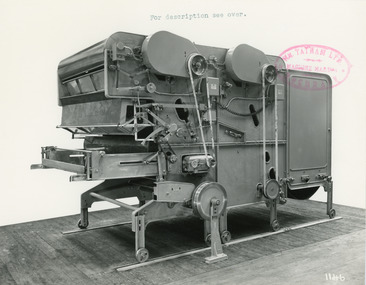
Photograph - Product Photograph, Automatic Feeding Machine
These are sales photographs for William Tatham Ltd. of Rochdale. These photographs are taken in the fitting shop at William Tatham Ltd. where final assembly would have taken place. The Automatic Feeding Machine automatically dispenses wool to a carding machine, so that an even, constant supply is received. This eliminated the manual labour previously needed for the initial weighing and feeding of wool. The photographed machine was made by William Tatham Ltd, a textile engineering company based in Rochdale, UK. Established in 1866, Tatham developed innovative textile machinery and sent their products to Australia and other countries around the world.Two black and white photos of an Automatic Feeding Machine in a landscape format. The first photo is of the front of the machine, the second is of the rear.8037.1 - Front - top margin: For description see over. Front mide right edge - Wm. TATHAM Ltd. ROCHDALE. Machine Maker Front bottom right corner - 1146 Rear - 78” wide Automatic Feeding Machine having Dual Hoppers in which the first and large section feeds the second Hopper so as to maintain a constant level of material in the latter. The driving of both spiked lattices is by electro-magnetic clutches, the one in the first Hopper being actuated by a sensitive feeler motion in the second, the second spiked lattice however, being controlled, of course, from the Scale Pan. Through a mercury switch. The scale is of our latest super-sensitive pattern mounted diagonally across the Feed. Only the opening doors are used in the actual weighting and the trap doors placed over the scale which close immediately the correct weight is deposited, operate through a solenoid. The machine incorporates many other features and is arranged to divide for facility in cleaning. 8037.2 - Front mide right edge - Wm. TATHAM Ltd. ROCHDALE. Machine Maker Front bottom right corner - 1147 Rear - Showing opposite side of Dual Automatic Feed illustrated in photo 1146textile machinery, automatic feeding machine, tatham, feeding machine -
 Ballarat Tramway Museum
Slide - 35mm slide/s - set of 14, Noel Simons, 23/11/1962 12:00:00 AM
Set of 14 Kodachrome transparencies taken on 23/11/1962. 1162.1 - tram 38 turning into Lydiard St. North from Sturt St. with tram 20 in background. Many motor vehicles in photo. 1162.2 - as above, but a minute of so later. Has Mutual Life building in background as well as Town Hall. 1162.3 - No. 40 entering Albert St. from Skipton St. outbound to Sebastopol. 1162.4 - No. 40 near start of side of the road running in Albert St. heading to Sebastopol. 1162.5 - No. 40 at the City terminus, on the South side of Sturt St. Has Town Hall and other buildings along the south side of Sturt St. in the background. 1162.6 - No. 40 at Sebastopol terminus - shows arrangement of the signs at the terminus. 1162.7 - No. 40 and No. 38 crossing at loop between Sayle and Grey St. No. 40 inbound. 1162.8 - No. 40 turning from Drummond St. South to Sturt St. at Hospital Corner with Southern Cross Hotel in background. 1162.9 - No. 18 in Wendouree Parade near Forest St. heading east with destination of "Victoria St." 1162.10 - Nos 41 and 39 at Depot Junction. Both trams have SEC ads. 1162.11 - No. 39 turning into the depot from Wendouree Parade - showing destination of "Gardens via Drummond Nth" 1162.12- No. 17 at Lydiard St. North terminus, showing destination of "Grey St. Sebas". Has a Twin Lakes sign 1162.13 - ditto, but with trolley pole turned around. Has SEC Briquettes roof ad and Whitehorse whiskey ad on rear dash panel. 1162.14 - No. 40 outbound to Sebastopol crossing Albert St. 1162.1 -"Nos. 38 and 20 in Sturt St. Ballarat at corner of Lydiard St." 1162.2 - "No. 38 turns into Lydiard St. as No. 20 waits at stop in Sturt St. Ballarat" 1162.3 - "No. 40 entering Albert St. from Skipton St. Redan on Sebastopol route." 1162.4 - "No 40 at beginning of reserved track on Sebastopol route, Albert St. Redan." 1162.5 - "No. 40 in Sturt St. Ballarat near cnr. of Armstrong St." 1162.6 - "No. 40 at Sebastopol terminus" 1162.7 - "No. 38 and 40 crossing at Sayle St. Loop on Albert St. reserved track, Sebastopol route" 1162.8 - "No. 40 turning into Sturt St. from Drummond St." 1162.9 - "No. 18 in Wendouree Pde. Ballarat near tramway depot" 1162.10 - "No. 41 and 39 outside Ballarat tramway depot, Lake Wendouree in background" 1162.11 - "No. 39 entering tramway depot from Wendouree Parade, Ballarat" 1162.12 - "No 17 at Lydiard St. North terminus, Ballarat North" 1162.13 - "No 17 at Lydiard St. North terminus, Ballarat North" 1162.14 - "No. 40 crossing Albert St. Sebastopol as reserved track switches from left to right of road" All have date stamp of "23 Nov. 1962" in purple ink. All black ink unless otherwise noted.tramways, trams, ballarat, albert st., sturt st., sebastopol, grey st., hospital corner, wendouree parade, depot junction, lydiard st. north, tram 17, tram 18, tram 20, tram 38, tram 39, tram 40, tram 41 -
 Ballarat Tramway Museum
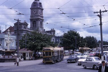
Photograph - Digital image Set of 10, Tony Smith, 5/09/1971 12:00:00 AM
Yields information about Ballarat Tramways and trams prior to the closure of the tramway system.Set of 10 digital images of Ballarat trams prior to closure, scanned from original slides by Tony Smith, 1971 prior to closure of the system. This set of slides, possibly on the last weekend of Mt Pleasant services - closure took place on 5/9/1971. . .1 - 30 rounding the curve from Lydiard St Nth to Sturt St. Tram has destination of Sebastopol. IN the background is the Commonwealth bank and the SEC cabinet switch isolator on the corner. .2 - 13 and another single trucker at the City terminus, north side with Racey's store and the SEC offices in the background. 13 has a Twin Lakes sign and the destination of Victoria St. .3 - 26 (Mt Pleasant) and 27 at the city terminus, with many passengers. Has the town hall in the background. .4 - 14 turning from Sturt St into Lydiard St (destination does not appear to be Lydiard St nth - City Oval?) with the ANZ bank in the background. A number of passengers waiting at the tram stop. .5 - 14 in Sturt St west near Pleasant St, at City Oval, with the pole being reversed by a "Bounds". Tram has the destination of City Oval. .6 - 13 west bound (showing Mt Pleasant) at Pleasant and Sturt St, with the VicRoads (CRB) offices and St Peters Anglican church in the background. .7 - 13 and 14 in Sturt St west, opposite City Oval (see .5 and .6) - trams reversing. .8 - 13 and 14 at Grenville St, about to cross into Bridge St from Sturt St. .9 - 14 at ditto - both trams for Mt Pleasant. Has the Patersons furniture store in the background. .10 - 30 eastbound in Sturt St, near Armstrong St with the Crockers store in the background. Tram showing "Special"trams, tramways, sturt st, electrical switching, city oval, lydiard st, pleasant st, grenville st, tram 30, tram 13, tram 26, tram 14