Showing 763 items matching "speed"
-
 Orbost & District Historical Society
letter/certificate, George V, after WW1
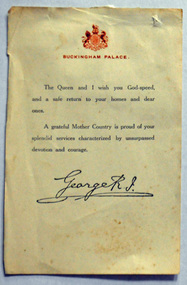
The RI stands for Rex Imperator. This letter / certificate was given to Don Dunoon (father of Lynn Brown) who served in World War 1. He later came to Orbost and married into the Lynn family - Mary Ellen Lynn. This certificate was given to all servicemen who survived the war. A World War I demobilization certicate / letter from Buckingham Palace to those who served in the Great War. At the head of the letter is the royal coat of arms and 'Buckingham Palace' letterhead in red printed ink. The text reads: 'The Queen and I wish you God-speed, and a safe return to your homes and dear ones. A grateful mother country is proud of your splendid services characterized by unsurpassed devotion and courage' Below is the ink printed signature of King George V - 'George R. I.' Additional information : These certificates were given to Dominion and Empire troops from Canada, New Zealand, Australia & etc., who had survived the Great War as it was then known. These documents were an Empire issue, not an issue for British service persons. R I is short for Rex Imperator which is Latin for King & Emperor. The document was sent to Colonial, Empire & Dominion troops only. This personal document gives an insight into the human element of World War 1 ensuring that those who were part of the Orbost community and died while playing a vital role during this time are remembered.A certicate / letter from Buckingham Palace to those who served in W W 11. At the top is the royal coat of arms and Buckingham Palace in red print. Print is black and it is signed by "George R.I."ww1 georgev dunoon-don -
 Melbourne Tram Museum
Document - Minute book - Cable tram operational history notes and records, Melbourne & Metropolitan Tramways Board (MMTB), up to 1930
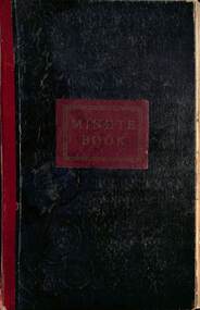
Compiled by an unknown person as a record book of cable tram operational tickets or fare history for each location with general notes and some notes on electric trams. Pages 1 to 23 and pages 123 and 124 - General history of cable and electric trams with notes on tickets, trams, buses, events, and operational management. Compiled through to 26/10/1930, with some loose notes about the final closure of the cable tram system. For each cable tram car house (depot), Power House or Winding house, or route, notes on tickets, dates, rope speed, fares, replacement electric services or buses. Richmond Fitzroy Fitzroy and South Melbourne line Victoria St Clifton Hill Nicholson St Exhibition (route or line) Brunswick Royal Park Carlton Prahran Toorak' Queensberry St North Carlton Esplanade with details on bus services Windsor St Kilda (Brighton Road) North Melbourne West Melbourne' South Melbourne Port Melbourne' Northcote Kew (horse) Elsternwick (electric) At rear of book is four page document that gives information on the electric tram system, routes, cable. fares and first and last services for each line. Mid 1920s as the West Coburg service noted. Yields information Melbourne cable tram fares, ticket issuing and general history of the MMTB.Book - heavy card covers with paper imitation leather finish with red tape on left hand side and labelled "Minute Book", bound with 8 sewn sections, approx 200 foolscap pages, ruled sheets, numbered in pencil from 1 to 124 used to record information in ink.tramways, cable trams, fares, tickets, electric trams, melbourne, mmtb -
 Plutarch Project
English wooden ship model, Cutty Sark replica, circa 1997
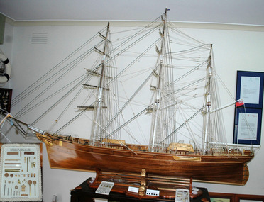
This replica ship was modelled to exact scale by Denis Paraskevatos with the original basic kit enhanced by a large number of brass and mahogany wooden parts used and showing on two labels positioned at the base of the model. These replica parts were specifically designed and constructed by D. Paraskevatos with the help of his family. This model along a large number of others have been displayed at the Victorian Parliament for ten days from the 18th March 2002 (Queens Hall) to the 28th March 2002, and the Melbourne Town Hall from 19th to 27th August 2004. The history of the 65 meter British vessel named Cutty Sark is as follows: THE CUTTY SARK (history) The “Cutty Sark” was a British clipper ship, aptly named of course as a [clipper for its speed ], which was built in 1869 on the [river Clyde in Scotland ] by the Jock Willis Shipping Corporation. It was primarily used to transport tea from China to Great Britain, as well to a lesser extent later in its life, wool from Australia; however, with the advent of the steam engines and the creation also of the Suez Canal in 1869, its days of operation as a sailing vessel were numbered, as the steam ships were now prevailing as technologically advanced cargo carriers through the shorter route by the Suez Canal to China. In fact, within a few years of its operation, as its delegation in the tea industry was declining, it was assigned primarily the duty of transporting wool from Australia to England, but this activity was thwarted again by the steam ships, as they were enabled by their technologies to travel faster to Australia. Eventually, the “Cutty Sark” in 1895 was sold to a Portuguese company called “Ferreira and Co.”, where it continued to operate as a cargo ship until 1922, when it was purchased on that year by the retired sea captain Wilfred Dowman, who used it as a training ship in the town of Falmouth in Cornwall. After his death, the ship was conferred as a gesture of good will to the “Thames Nautical Training College” in Greenhithe in 1938, where it became an auxiliary cadet training ship, outliving its usefulness as a training vessel by 1954, and permanently [being dry docked in Greenwich, London, ] for public viewing. Of course, the “Cutty Sark” was not the only tea clipper constructed and owned by the Jock Willis Corporation, as there were others who were also used for the transportation of tea from China to Great Britain. Noteworthy additionally in its impressive resume is the fact that, the “Cutty Sark” was not only valued and admired for its speed, but also for its prestige that it afforded to its owners, [as media coverage was insatiable during a tea race that was regarded a national sporting event, with fiscal bets being placed on a predicted winning ship ]. Disappointingly, even though the English tea clippers were the best in the world at the time in terms of marine design, they had never won a tea race, and Jock Willis was certainly determined to achieve this goal, as the American clippers were considered the fastest in the tea trade. Nonetheless, the British clippers were proven to be formidable opponents to their American counterparts in the tea trade, when in 1868 a British tea clipper called [“Thermopylae”, managed to travel from the port of London to Melbourne, in only sixty one (61) days, which Jock Willis was hoping to improve on such a feat with the “Cutty Sark” ] . Remarkably, the maximum speed that the “Cutty Sark” could achieve was 17.5 knots in spite of the challenges of the unpredictable winds, if any at times, and the high seas or ferocious storms. Interestingly, [the “Cutty Sark’s” greatest recorded achievement in distance in twenty four (24) hours was three hundred and sixty three (363) nautical miles ], which meant that it was averaging approximately fifteen (15) knots; much faster obviously than the recorded twenty four (24) hour distance of the “Thermopylae” which had accomplished three hundred and fifty (358) nautical miles. .... ______________ -*- Please read the complete history of the Cutty Sark vessel by Maria Paraskevatos in one of the attachments provided with this exhibit. This model along with a large number of others was constructed by the Master craftsman Denis Paraskevatos, in Melbourne and has a historic, artistic significance because of the time and artist efforts in construction.The English Cutty Sark replica model is a wooden replica scaled at 1:25. The wood is mahogany and it is normally displayed in a glass covered enclosure. It has three masts and it is the largest vessel of Denis Paraskevatos collectionCUTTY SARK LONDONreplica, ship, art, model, cutty, sark, greek, artist, paraskevatos, παρασκευάτος, πανομοιότυπο -
 Bendigo Historical Society Inc.
Document - NEW CHUM & VICTORIA LINES OF REEF - MINING MACHINERY, NEW CHUM LINE, EAGLEHAWK
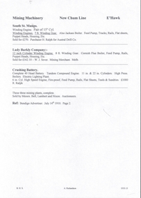
Handwritten notes on mining machinery sold at auction. South St Mungo - Winding Engine. Pair of 15 ? Cyl. Winding Engines. 7 ft Winding Gear. Also, Jackass Boiler. Feed Pump, Trucks, Rails, Flat Sheets, Poppet Heads, Housing, etc. Sold for 270 pounds. Purchaser H Ralph for Austral Drill Co. Lady Barkly Company - 12-inch Cylinder Winding Engine. 8 ft Winding Gear. Cornish Flue Boiler, Feed Pump, Rails, Poppet Heads, Housing, etc. Sold for 162 pound 10 shillings. Purchaser W. J. Sever, Mining Merchants, Melb. Crushing Battery - Complete 40 Head Battery. Tandem Compound Engine. 11 in & 22 in Cylinders. High Press, Boilers, Electric Lighting Plant. 6 in Cyl. High Speed Engine, Fire-proof, Feed Pump, Rails, Flat Sheets, Tools & Sundries. 1000 pound to R. Ralph. These three mining plants, complete. Sold by Messrs. Bell, Lambert and Nixon - Auctioneers. Ref; Bendigo Advertiser. July 14th, 1910, Page 2.document, gold, new chum & victoria lines of reef, mining machinery new chum line eaglehawk, south st mungo, h ralph, austral drill co, lady barkly company, w j sever, crushing battery, messrs bell, lambert and nixon -
 The Beechworth Burke Museum
Animal specimen - Australian Hobby, Trustees of the Australian Museum, 1860-1880
Hobbies are mainland birds that prefer to spend their time in forests and woodlands. They are widespread in Australia's colder eastern states, particularly Adelaide, Victoria, and Southern NSW. With a diet of bats, insects, and small birds, they use their refined wing structure, which is long and narrow in shape, more suited to speed than precision, and sharp reflexes to catch prey in mid-flight. Because they are members of the Falconidae and Falconiformes raptor families and have similar characteristics, they are frequently confused with their relative, the Peregrine Falcon. Close inspection reveals that they are half the size and have a more pronounced dark masking around the eyes. This specimen is part of a collection of almost 200 animal specimens that were originally acquired as skins from various institutions across Australia, including the Australian Museum in Sydney and the National Museum of Victoria (known as Museums Victoria since 1983), as well as individuals such as amateur anthropologist Reynell Eveleigh Johns between 1860-1880. These skins were then mounted by members of the Burke Museum Committee and put-on display in the formal space of the Museum’s original exhibition hall where they continue to be on display. This display of taxidermy mounts initially served to instruct visitors to the Burke Museum of the natural world around them, today it serves as an insight into the collecting habits of the 19th century.This specimen is part of a significant and rare taxidermy mount collection in the Burke Museum. This collection is scientifically and culturally important for reminding us of how science continues to shape our understanding of the modern world. They demonstrate a capacity to hold evidence of how Australia’s fauna history existed in the past and are potentially important for future environmental research. This collection continues to be on display in the Museum and has become a key part to interpreting the collecting habits of the 19th century.The Australian Hobby is a medium-sized bird with a falcon-like appearance, long wings, and a commanding posture and presence. This bird has a distinctive brown/black helmet on its head, as well as a mask-like face that is highlighted by the prominent white half collar. Over the top of reddish brown underpart feathers, streaks of black lined patterns decorate the protruding chest. With its squared off tail feathers, the bird's back is dark brown and appears elongated and domineering. It is perched on a wooden stand and is secured with wire that does not obscure the talons.No swing tagtaxidermy mount, taxidermy, animalia, burke museum, beechworth, australian museum, skin, reynell eveleigh johns, bird, australian birds, falcon, falconidae, falconiformes, peregrine falcon -
 Eltham District Historical Society Inc
Photograph, Fay Bridge, The Tree Project, 2009
Australia's worst natural disaster, fed by extreme temperatures, tornado-like wind speeds and tinder-dry land, culminated in the disaster we now know as Black Saturday, February 7, 2009. Before the sun would set on the blackest day in Australia's history, thousands of hectares would become blackened landscape and an unparalleled loss of lives could only mean that many areas would never be the same again. To remember the people lost to the devastating Black Saturday fires of 2009 and our brave CFA men and women who battled the elements to protect our towns, the Australian Blacksmiths Association (Victoria) Inc. invited blacksmiths from across the country and around the world to contribute to the creation of a steel gumtree. The Blacksmiths' Tree, as it came to be called, was erected on February 14, 2014. Five years in the making, this 10m high stainless steel and copper tree was forged with love and care by hundreds of blacksmiths across 20 countries. It stands in the township of Strathewen, Victoria, Australia to remember all of those who perished in the Black Saturday fires of 2009, those who fought the fires and those who continue to live their lives with hope and courage. The tree stands at the Peter Avola Memorial Pavilion, 160 Chadds Creek Road, Strathewen, Victoria.fay bridge collection, black saturday, kinglake, victorian bushfires - 2009, the tree project -
 City of Moorabbin Historical Society (Operating the Box Cottage Museum)
Newsletter - City of Moorabbin Historical Society, Newsletter No 1 August 1961, 1961
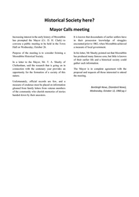
This is No.1 the first Newsletter produced by CMHS members in August 1961. Topics : October 1960 Mayor Cr. D.H. Clark called a meeting in the Moorabbin Town Hall to form the City of Moorabbin Historical Society. Local residents attended including descendants of early settler families - Coates, LePage, Shipston - and a Committee was elected. Mr T.A.Sheehy, President, Mr R.Colbourne, Secretary, Mrs F.Wright, Treasurer set the Annual Membership Fee at 5/- ( shillings), arranged the next meetings at the Moorabbin Town Hall and began to compile a Newsletter to tell the ' story of Moorabbin'. The Cheltenham & District Society Co-operative Limited (est.1896) sponsored this 1st CMHS Newsletter published August 1961. The Aims of the CMHS are ‘to record the history of the City, and register something of the Australian Atmosphere, which the necessary speed-up in post-world-war two (WW11) immigration has caused to be lost; to produce a magazine at regular intervals, featuring the work of pioneers and the changing Australian scene; to work constantly with a long range view towards building a hall where records and exhibits can be housed’ The Original Newsletters reflect the history and heritage of the former City of Moorabbin — derived from Mooroobin, ‘a resting place’ in the Bunurrung spoken language. In 1994, the City of Moorabbin was integrated into the Cities of Bayside, Glen Eira, Kingston and Monash. This is the 1st Newsletter of CMHS in August 1961 CMHS obtained a Kingston City Council Community Grant 2016 for the digitization and preservation of these Original CMHS Newsletters commenced in 1961 Foolscap paper printed on 1 side.CITY OF MOORABBIN HISTORICAL / SOCIETY / NEWSLETTER No 1 / AUGUST 1961moorabbin, cheltenham, bentleigh, newsletters,, sheehy thomas, coates l.r, shipston h, lepage e.a, lepage f.w., blackburn nance, clark d.h., wright f, moorabbin city council, cheltenham and district society co-operative limited, moorabbin town hall, early settlers, market gardeners, pioneers, dendy henry, brighton, box william, bent thomas -
 Puffing Billy Railway
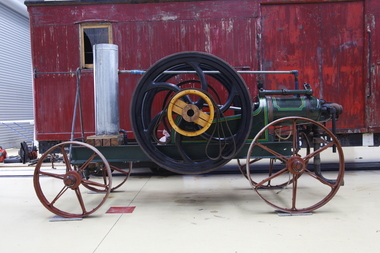
Blackstone Oil Engine, 6 November 1908
8HP Blackstone Lamps Start Oil Engine engine number 71076 Engine Details Maximum operating RPM of 240. Fitted with a 3'9" Flywheel Tested on the 6th of November 1908. Shipped to Cluter buck South Australia for installation on concrete base. Recovered and restored during the 80's in South Australia Purchased privately in 2013 in Tailem Bend South Australia and transported to Victoria. Currently on loan to the Puffing Billy Museum at Menzies Creek as an operating exhibit. Blackstone & Co. was a farm implement maker at Stamford, Lincolnshire, United Kingdom. In 1896 they built lamp start oil engines. The Lamp or hot-bulb engine (also hotbulb or heavy-oil engine) is a type of internal combustion engine. It is an engine in which fuel is ignited by being brought into contact with a red-hot metal surface inside a bulb, followed by the introduction of air (oxygen) compressed into the hot-bulb chamber by the rising piston. There is some ignition when the fuel is introduced, but it quickly uses up the available oxygen in the bulb. Vigorous ignition takes place only when sufficient oxygen is supplied to the hot-bulb chamber on the compression stroke of the engine. Most hot-bulb engines were produced as one-cylinder, low-speed two-stroke crankcase scavenged units Historic - Industrial - single cylinder, horizontal, 4 stroke, hot-bulb ignition oil engine Blackstone 8HP Oil Engine made from steel, wrought iron and brassOval Plate with Black Stones and Clutter Buck Brass Plaque engine number 71076blackstone, oil engine, clutter buck, black stone, puffing billy, hit and miss, engine, blackstone & co -
 Westbourne Grammar Heritage Collection
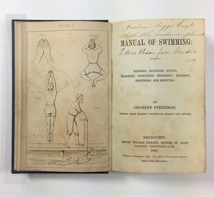
Book - Charles Steedman, 1867, Manual of Swimming
Charles Steedman was headmaster of Williamstown Grammar School from 1870-76 and 1885-90. In 1870, under agreement with school trustees, Sir George Verdon and John Courtis, he leased the school under a seven-year lease, effectively saving it from closure. Steedman had previously been manager of Sandridge Baths and a champion swimmer of Victoria. His 1867 book, 'Manual of Swimming', was the first major technical contribution to the sport of speed swimming and water safety, for which Steedman was inducted into the Sport Australia Hall of Fame in 2006. As headmaster of Williamstown Grammar, Steedman initiated a student produced school paper called 'The Schoolboy' (surviving editions can be accessed at the State Library of Victoria), added swimming lessons to the curriculum and opened enrolment to girls in 1885. The book contains nine illustration plates featuring line drawings of a human figure in the positions detailed by Steedman in his text. These drawings are attributed to O.R. Campbell. Oswald Rose Campbell is best known for his appointment (1876-1886) as drawing master of the School of Design, a department of the Public Library, Museums and National Gallery of Victoria. He taught (and famously disagreed with) the likes of celebrated Australian artists, Tom Roberts and Frederick McCubbin. O.R Campbell taught drawing and painting at Williamstown Grammar in the early 1870s.The book holds historic significance for Westbourne Grammar School, having been written by a former headmaster and very important figure in the history of the school. It evokes our early history as an emerging grammar school with links to prominent athletes, artists and gentry of colonial Melbourne. Blue cloth covered case-bound book, with debossed decorative scrollwork in each corner and in the centre of front cover, and gilt lettering on the spine. 270 numbered pages, nine illustration plates (one adjacent to title page, eight as end pages).On title page, handwritten inscriptions in brown coloured ink. Possibly ‘Joshua Saggs Esq. / With the authors compliments’ and below, in different handwriting and darker ink, ‘To dear Flossie from Grandma 1901’. williamstown, sandridge baths, swimming, colonial melbourne, art, williamstown grammar -
 Queenscliffe Maritime Museum
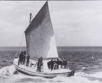
Photograph - Queenscliff Lifeboat under sail, 06 March 1926
The Lifeboat Queenscliffe was built in Adelaide and commenced service at Queenscliff in 1926. She was taken out of service in 1976 by the Marine Board of Victoria and subsequently offered to the Borough of Queenscliffe for care and display. The Lifeboat is listed on the Australian Register of Historic Vessels (ARHV). To view the classification follow the link to the Queenscliffe page on the ARHV site. During her 50 years of service the Queenscliffe attended many calls for assistance both inside and outside the Heads. Some of the vessels and calls for help the lifeboat attended were: 1960 - Army Commandos lost in the Rip 1967 - The search for the late Prime Minister Harold Holt 1974 - The last attendance to a vessel was to the Brisbane Trader which was on fire The shed which housed the lifeboat is located on the Queenscliff 'New' or 'Steamer' Pier (built in 1884). This shed includes the internal section of the slipway used to launch and retrieve the lifeboat. The external slipway and some other structures associated with the lifeboat shed have been removed. Originally fitted with two masts, the stern mast being removed in the 1960's. A retractable centre plate was used when under sail. Delivered with an 80 hp Wayburn petrol motor which was later replaced by a 72 hp Gardiner diesel. Top speed of 7.5 knots and a range of 350 miles.Photograph of lifeboat Queenscliff at sea under sailQueenscliffelifeboat, a. macfarlane & sons -
 Department of Energy, Environment and Climate Action
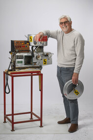
Incendiary machine
The Canadians developed a machine that used "ping pong balls" instead of cylindrical incendiary capsules and, in 1977, the FCV purchased a Premo machine for evaluation. The 32mm-diameter balls were made from high impact polystyrene and contained 3.5g of potassium permanganate. They were injected with 1ml of glycol which would ignite after a short delay The first Premo machine used four slipper blocks, which were loaded via a hand-operated hopper which, when rotated forward, the balls would be fed into four feed chutes to individual slipper blocks. Each slipper block has an opening allowing individual balls to enter and exit once injected. The original design of the machine was not suitable to meet the burning objectives and a number of modification were necessary. Following close inspection and field testing it was clear that utilising four slipper blocks was excessive and would generate too much fire. It was acknowledged that satisfactory spacing could be achieved by using just one slipper block. Selective spacing could be achieved by the speeding up or slowing down of the slipper block transferring the capsules during the injection process. Regulating the speed that the injected capsules were being dropped controlled the amount of fire created on the ground. This machine was the result of many years of experimentation at AltonaSignificant development of aerial incendiary machines enabled expansion of the fuel reduction burning program across Victoria.Aerial Incendiary machine for use in helicopters Modification at the Altona workshops over many years by Barry Marsden forests commission victoria (fcv), planned burning, bushfire, bushfire aviation -
 The Beechworth Burke Museum
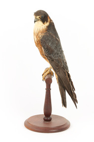
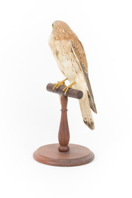
Animal specimen - Nankeen Kestrel, Trustees of the Australian Museum, 1860-1880
The Nankeen Kestrel, also known as the Australian Kestrel, is a common native to the open country's grasslands and farmlands, preferring agricultural areas. They are drawn to animal pests like mice, insects, small animals, reptiles, and birds. Due to the shape and ability of their tail feathers, which allows them to hoover over their prey, they do not rely on speed to catch their meal like most falcons in their family group. These birds are among the smallest raptors in the Falcon family, having well-known face characteristics and body shapes. The females of the species are distinguished by their darker patterns and red-brown (rufous) tones, as well as their larger size, whilst the males are more greyish. The yellow markings around the eyes and top of the beak, as well as the noticeable black dipped wings, distinguish each species. This specimen is part of a collection of almost 200 animal specimens that were originally acquired as skins from various institutions across Australia, including the Australian Museum in Sydney and the National Museum of Victoria (known as Museums Victoria since 1983), as well as individuals such as amateur anthropologist Reynell Eveleigh Johns between 1860-1880. These skins were then mounted by members of the Burke Museum Committee and put-on display in the formal space of the Museum’s original exhibition hall where they continue to be on display. This display of taxidermy mounts initially served to instruct visitors to the Burke Museum of the natural world around them, today it serves as an insight into the collecting habits of the 19th century.This specimen is part of a significant and rare taxidermy mount collection in the Burke Museum. This collection is scientifically and culturally important for reminding us of how science continues to shape our understanding of the modern world. They demonstrate a capacity to hold evidence of how Australia’s fauna history existed in the past and are potentially important for future environmental research. This collection continues to be on display in the Museum and has become a key part to interpreting the collecting habits of the 19th century.The Nankeen Kestrel is a small raptor in the Falcon family. It has a stockier appearance, with the upper parts of its body, such as the head and the tops of its wings, being a light red-brown (rufous) colour and the tips of its wings appearing dipped in black. The top of the beak and the eye rings are both yellow, and this bird's falcon appearance shows its inherent dark streak markings visible near the eyes and on the chest. The underparts are pale, with a tail feather that spreads out to help it hover and is ornamented with fine black decorations.20. / Unnamed / Catalogue page 5 / taxidermy mount, taxidermy, animalia, burke museum, beechworth, australian museum, skin, reynell eveleigh johns, bird, nankeen kestrel -
 4th/19th Prince of Wales's Light Horse Regiment Unit History Room
Transmission Assembly, Ferret Scout Car, Daimler, c 1950
The Ferret Scout Car , was developed by the British Army in the late 1940s and came into production in the 1950s. The Ferret first saw service in the British Army in 1952, and a little later in Australia. There were many series and Marks of the Ferret. In Australia two were primarily used. The Mark1, which had no turret and a crew of three, and the Mark2, with a turret and a crew of two. The Australian Army used the Ferrets as scout cars until the 1960s, they were disposed of by public auction in the early 1970s. The Ferret is a light armoured car, intended for light reconnaissance work, they are very mobile and were well suited to their role. The vehicle was designed by Daimler, as a further development on the successful Daimler Dingo of WW2. The Ferret is fully armoured and the standard model of the Ferret Mk2 was further strengthened shortly after its design and became the Mk2/3 (this is the usual model referred as the Mk2). The motor was Roll Royce B60 motor, giving the vehicle a power to weight ratio of 29.35 break horse power per tonne, the vehicle weighs 3.6 tonnes, although a combat weight would be 4.3 tonnes. It is four wheel drive, constant, and has a top speed of 93 k.p.h. (approx 50 m.p.h.). Fuel consumption is only about 34 litres per kilometer. The Ferret is 3.8 metres long by 1.9 metres wide and is 1.9 metres high, not including radio aerials. The ground clearance is .33 of a metre and the track width is 1.5 metres.Ferret Scout Car - B60 No 1 Mk 6A transmission assembly incorporating engine, fluid coupling, gear box and transfer box.Engine Number 12993 List Number 35418 Modification plate marked to Mod 3. ferret scout car, transmission -
4th/19th Prince of Wales's Light Horse Regiment Unit History Room
Transmission Assembly, Ferret Scout Car
The Ferret Scout Car Mark 2, was developed by the British Army in the late 1940s and came into production in the 1950s. The Ferret first saw service in the British Army in 1952, and a little later in Australia. There were many series and Marks of the Ferret. In Australia two were primarily used. The Mark1, which had no turret and a crew of three, and the Mark2, with a turret and a crew of two. The Australian Army used the Ferrets as scout cars until the 1960s, they were disposed of by public auction in the early 1970s. The Ferret is a light armoured car, intended for light reconnaissance work, they are very mobile and were well suited to their role. The vehicle was designed by Daimler, as a further development on the successful Daimler Dingo of WW2. The Ferret is fully armoured and the standard model of the Ferret Mk2 was further strengthened shortly after its design and became the Mk2/3 (this is the usual model referred as the Mk2). The motor was Roll Royce B60 motor, giving the vehicle a power to weight ratio of 29.35 break horse power per tonne, the vehicle weighs 3.6 tonnes, although a combat weight would be 4.3 tonnes. It is four wheel drive, constant, and has a top speed of 93 k.p.h. (approx 50 m.p.h.).Fuel consumption is only about 34 litres per kilometer. The Ferret is 3.8 metres long by 1.9 metres wide and is 1.9 metres high, not including radio aerials. The ground clearance is .33 of a metre and the track width is 1.5 metres.ferret scout car, transmission -
 Flagstaff Hill Maritime Museum and Village
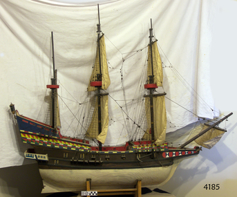
Craft - Ship model, Golden Hind
This is a ship model of the famous galleon the "Golden Hind". About the “Golden Hind” The English galleon “Golden Hind”, a mid-16th century Elizabethan warship, was launched in 1577. It was formerly known as the “Pelican”. The Golden Hind was the flagship of Captain Sir Frances Drake, in which he became the first Englishman to circumnavigate the world 1577-1580. Tonnage 100-150 tons Displacement 300 tons [fully loaded] Speed 8-15 knots Armament 22 guns Crew 80 sailors, 10 officers Built Aldeburgh, Suffolk, then moved to Plymouth, Devon in 1576 Type of ship Galleon; multi-decked ship (5 decks), square rigged, 3 masted sailing ship Estimated size Length - 70 feet (21.3m); Breadth – 19 feet (5.8m); Depth – 9 feet (2.7m) The Pelican set sail in 1577 on an expedition sponsored partly by Queen Elizabeth and Sir Christopher Hatten (whose family crest was a golden hind). His companion ships were the Swan, Marigold, Benedict and the Elizabeth. During this voyage, in 1578, Drake renamed the Pelican as the Golden Hind in honour of is patron. Sir Francis Drake [1544 – 1596] brought the Golden Hind home from his circumnavigation of the globe with looted gold, percelain, jewels and cash worth 35,000,000 million pounds in today’s money. It was the largest treasure every captured at that date. Only two ships returned – the “Golden Hind” and the “Elizabeth”. The ship model of the Golden Hind captained by Sir Frances Drake represents the first English circumnavigation of the globe.Ship model of the16th century galleon "The Golden Hind", Sir Francis Drake’s flagship (not in a glass case.) flagstaff hill, warrnambool, shipwrecked coast, flagstaff hill maritime museum, maritime museum, shipwreck coast, flagstaff hill maritime village, great ocean road, ship model, model ship, galleon golden hind 1577, galleon golden hinde 1577, galleon pelican 1577, 16th century galleon, 16th century warship, sir frances drake, captain frances drake, first englishman to circumnavigate the globe -
 Flagstaff Hill Maritime Museum and Village
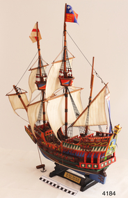
Craft - Ship Model, Golden Hind
This is a ship model of the Golden Hind. About the “Golden Hind” The English galleon “Golden Hind”, a mid-16th century Elizabethan warship, was launched in 1577. It was formerly known as the “Pelican”. The Golden Hind was the flagship of Captain Sir Frances Drake, in which he became the first Englishman to circumnavigate the world 1577-1580. Tonnage 100-150 tons Displacement 300 tons [fully loaded] Speed 8-15 knots Armament 22 guns Crew 80 sailors, 10 officers Built Aldeburgh, Suffolk, then moved to Plymouth, Devon in 1576 Type of ship Galleon; multi-decked ship (5 decks), square rigged, 3 masted sailing ship Estimated size Length - 70 feet (21.3m); Breadth – 19 feet (5.8m); Depth – 9 feet (2.7m) The Pelican set sail in 1577 on an expedition sponsored partly by Queen Elizabeth and Sir Christopher Hatten (whose family crest was a golden hind). His companion ships were the Swan, Marigold, Benedict and the Elizabeth. During this voyage, in 1578, Drake renamed the Pelican as the Golden Hind in honour of is patron. Sir Francis Drake [1544 – 1596] brought the Golden Hind home from his circumnavigation of the globe with looted gold, percelain, jewels and cash worth 35,000,000 million pounds in today’s money. It was the largest treasure every captured at that date. Only two ships returned – the “Golden Hind” and the “Elizabeth”. This Ship model of the galleon Golden Hind, the flagship of Captain Sir Frances Drake, represents the first circumnavigation of the globe by an Englishman.Ship model, the galleon Golden Hind on timber stand. Square rigged with 2 masts each with a flag and crow's nest. 22 guns on decks. Brown hull with green stripes and decorative coloured trimmings. Nameplate "Sir Francis Drake - his ship / The Golden Hind - 1577-1580". Emblem with animal golden hind, Tudor Rose and lamp above. Nameplate "Sir Francis Drake - his ship / The Golden Hind - 1577 - 1580"flagstaff hill, warrnambool, shipwrecked-coast, flagstaff-hill, flagstaff-hill-maritime-museum, maritime-museum, shipwreck-coast, flagstaff-hill-maritime-village, ship model, model ship, galleon golden hind 1577, galleon golden hinde 1577, galleon pelican 1577, 16th century galleon, 16th century warship, sir frances drake, captain frances drake, first englishman to circumnavigate the globe -
 Geelong Football Club
Geoff Williams Scrapbook
Loaned to the Geelong Football Club by Mr Geoff Williams for the purposes of digitisation. Geoff Williams Born: 18/11/1930 From: East Geelong via Warragul Height: 183cm Weight: 83kg Natural kicking foot: Right Guernsey number: 21 First senior match: Round 1, 1952 v Melbourne at the MCG The fast mover quickly established himself as a top half-back flanker. His ball-winning skill, judgment and ability to concentrate were obvious. He always played the game fairly but strongly, and no player tried harder to perform well. His kicking wasn’t stylish but generally it was effective. He liked to knock the ball clear of opponents and shoot after it at great speed. He won the club Best and Fairest award in his first season – an outstanding achievement in a Premiership year. Total Brownlow Medal votes: 22 Premiership team selection: 1952 Club Best & Fairest: 1952, 1955 GFC Hall of Fame inductee (2002) GFC Life Membership (1959) Career span: 1952-59 Total matches: Premiership 121, Night/Pre-Season Series 4 Total goals: Premiership 1, Night/Pre-Season Series 0 Finals matches: 9 Finals goals: 0 Last senior match: Round 5, 1959 v Essendon at Windy Hill Information provided by Mr Col Hutchinson GFC Historian Scrapbook detailing the recruitment and career of Geelong Champion Geoff Williams. 54 pages in totalgeoff williams, half back, premiership player, geelong cats -
 Wodonga & District Historical Society Inc
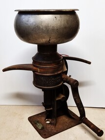
Machine - Cream Separator
A separator is a centrifugal device that separates milk into cream and skimmed milk. Separation was commonly performed on farms in the past. Most farmers milked a few cows, usually by hand, and separated milk with a hand operated machine for domestic use. The milk was poured into the bowl on the top and the handle had to then be turned fast enough to get the separator up to speed adequate to separate the cream and the milk. The milk would come out of one spigot and the cream out of the other. In general practice some of the skimmed milk was consumed by the family, while the rest may have been used to feed calves and pigs. Enough cream was saved to make butter, and the excess was sold. In many cases excess could be bartered or swapped with neighbours for other items of produce. ALFA-LAVAL SEPARATORS The principal works and head office of Aktiebolaget Separator was established by Gustaf de Laval in Stockholm. The first Laval milk separator was patented in1884. In Australia three old established firms commenced pioneering the Alfa Laval cream separators in about 1885. These were A. W. Sandford & Co. Ltd., in Adelaide, J. Bartram & Son, of Melbourne, who have ever since been the Victorian agents of Aktiebolaget Separator. In New South Wales and Queensland, the pioneering firm was Waugh & Josephson Ltd. J. Bartram & Son, the distributor of the separator in this collection, established their business in Melbourne in 1881. In 1892 Bartram & Son estimated that 1,130 of these machines were operating throughout Victoria. This item is significant as it is representative of domestic and dairying machinery used throughout rural areas of Australia in the early to mid 20th century.The separator is made in 3 sections. The base is made from cast iron. The cover and vat are made from silver painted tin. There are 2 outlet spouts. The detachable handle, made from cast iron and wood, is held in place by a screw. A name plate featuring the Victorian distributor, J Bartram & Son of Melbourne and a plate outlining patent information are attached to the base by screws.Around edge of wheel "Aktiebolaget Separator Stockholm/ 2236"dairying industry, dairy machinery, milk separators -
 Department of Energy, Environment and Climate Action
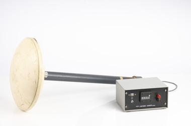
Lightning Detector
Lightning is one of the major causes of bushfires, particularly in the remote mountains. This lightning detector system was developed by Dr. Peter Kourtz at Canada’s forest fire research institute. By 1977, some 300 were in use across the country. The small mushroom antenna could detect short-range (20-mile) changes in electrostatic field associated with lightning strikes. It needed to be placed out in the open on a hilltop and away from nearby trees. It simply counted the number of "strikes". The detector doesn't seem to have a direction finding capability or be able to distinguish between cloud-to-cloud or cloud-to-ground lightning. It's not sure how this particular unit found its way to Victoria. The Bureau of Meteorology's (BOM) current lightning detector network uses radio waves emitted by lightning to pinpoint the location of lightning strikes. The network is operated by a private company that sends data to the BOM in real time. Lightning detection systems use sensors like antennas, GPS receivers, and processing systems to detect radio waves, also known as sferics. The systems calculate the lightning's location and speed by measuring how long it takes for the radio signal to reach the different antenna stations. The BOM also has a Thunderstorm Tracker that uses weather radar data to identify areas of potential thunderstorm activity. The tracker updates every six minutes and shows the direction thunderstorms are moving, as well as their expected position in 10, 20, and 30 minutesLightning detector 1970sQ-Techforests commission victoria (fcv), weather, bushfire, bushfire aviation -
 Trafalgar Holden Museum
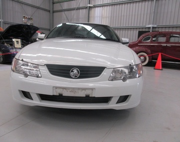
Vehicle - VY Acclaim sedan, 2002
The front and rear of the body had minor restyling, with new front grille, headlights and taillights. The interior has been significantly upgraded. Interior upgrade includes a new instrument panel, centre console and steering wheel and new design transmission lever and handbrake.[2] There is also a new mobile phone power outlet under the centre console. The new instrument cluster features a large multi-function digital display (single or triple-window, depending on model), which displays information such as radio station display, PRND321 gear selected indicator, trip computer with stopwatch function, service reminders and a help facility. Standard features (on some models) now include "twilight sentinel" - automatic headlamp control, programmable headlamps off time delay, high feature Blaupunkt audio systems, road-speed sensitive intermittent wipers and passenger airbags. The VY Series II update added cruise control, front power windows variable front seat lumbar support, and revised interior trims. A 245 kW (329 hp) V8 was introduced to sports variants and a sportier repositioning of the Calais model. This repositioning included a subtle body kit, the option of a 235 kW V8 in place of the previous 225 kW (302 hp) and a firmer suspension tune (known as FE 1.5) that was not as stiff as the FE2 suspension on sports variants. Released in September 2002 and produced until August 2004 (with a Series II released in August 2003), the VY series was the first major design departure (both inside and out) of the third generation Commodore range released in August 1997. It launched at the same time as the Ford Falcon (BA).VY Holden 4 door sedan white paint with grey fabric upholsteryLion and stone emblem grille centre, V6 badge on mudguards, Commodore badge on boot LHS, Lion and stone badge on boot centre, Acclaim badge RHS of boot lidvehicle, commodore, car -
 Seaworks Maritime Museum
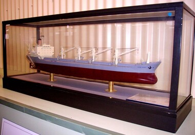
Shipbuilders model, Cape Otway
In 2010, the Government announced that the ETV fleet would be no longer be funded by the MCA from September 2011, saving £32.5m over the Spending Review period. The Department stated that "state provision of ETVs does not represent a correct use of taxpayers money and that ship salvage should be a commercial matter between a ship's operator and the salvor".Two days after the announcement that the fleet was to be disbanded, Anglian Prince was sent to the aid of the UK's newest and largest nuclear submarine HMS Astute, which ran aground off the Isle of Skye in Scotland during sea trials. 1977 owners became Cape Otway Ltd, same managers 1978 Owners became Otway Shipping Co LTD, same managers August 1981 Returned to owners and bareboat chartered to the Australian National Line 1987: Sold, k/s Hansa Bulk 2. Barber International A/S managers. Renamed HANSA MARINER. Norway flag 1988 Sold K/S Stamariner. Helmer Staubo and Co Managers, renamed Stamariner. Norway (NIS flag) 1993: Sold Shipping Enterprise, renamed Tamarine, Malta flag 1998: sold renamed Andromechi 1998: Sold, Golden Union Shipping Co S.A Panama flag, renamed Flag Braveheart 2000: sold, Flag Sofia Shipping Company Ltd. renamed Flag Sofia. Malta flag. November 15th reported as being on fire at St Petersburg. Damage to the Officer's dining room, laundry and alleyways 2002: Sold Emirates Shipping Corporation Ltd. Emirates Trading Agency LLC, managers. Renamed PEARL OF ASMAN then amended PEALR OF AJMAN. Malta Flag 2003: March sold for scrap to ship breakers in BangladeshShip builder's model of the bulk carrier Cape Otway IMO 7520229 built by Misui Engineering & Shipping Co. The burgundy and grey hull beneath a deck with detailed fittings and superstructure, presented within a glazed display case. On base of case: " M.V CAPE OTWAY/ OWNER : LYLE SHIPPING CO., LTD/ BUILDER : MITSUI ENGINEERING & SHIPBUILDING CO., LTD CHIBA WORKS/ BUILDER'S NO.: 1093/ CLASS: LLOYD'S REGISTER OF SHIPPING/ DEADWEIGHT...32,504KT/ LENGTH (OVERALL)... 179.000M/ LENGTH (P.p) 170.000M/ BREADTH (MLD)... 14.800M/ FULL LOAD DRAFT (EXT)... 10.677M/ MAIN ENGINE: MITSUI B&W 7K 74EF X 1 SET/ M.C.O.: 13,100 BHP X 124 RPM/ C.S.O: 11,900 BHP X 120 RPM/ TRIAL MAX. SPEED: 17.50 KTS 9AT = 17,870 KT, M.C.O.)/ DELIVERED : DECEMBER, 1976/ SCALE: 1/200" On model: "CAPE OTWAY/GLASGOW" -
 Royal Melbourne Yacht Squadron
Memorabilia - Wheel of HMAS Sydney, Early 20th Century
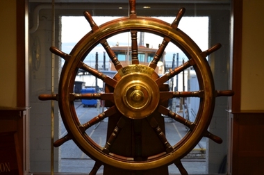
THE WHEEL OF HMAS SYDNEY COMMEMORATING AUSTRALIA’S FIRST NAVAL ENGAGEMENT The historic wheel of HMAS Sydney commemorates the Royal Australian Navy’s first ship- to- ship naval engagement. It was purchased early in 1930 and later presented to the Royal St Kilda Yacht Club (now Royal Melbourne Yacht Squadron) by then Commodore Joe White, following HMAS Sydney being broken up at Cockatoo Dock, Sydney. On 1 November 1914, led by the flagship SS Orvieto, a large convoy of 28 Australian and 10 New Zealand transports escorted by the Light Cruisers HMAS Melbourne, HMAS Sydney, HMS Minotaur and the Japanese ship Ibuki, departed King George Sound, Albany Western Australia with a large contingent of Australian and New Zealand troops bound for Egypt, to become the original Anzac’s. As the convoy steamed northwest across the Indian Ocean, leaving Cocos-Keeling Islands well to the westward, Captain Karl von Muller in the German Light Cruiser Emden of 3,600 tons, after having wrought much havoc to allied shipping in the Indian Ocean, ignorant of the convoys presence, had in mind to destroy the Cocos Island Cable Station on Direction Island. In the early hours of the morning of Monday the 9 November, he anchored “Emden” off Direction Island to send a landing party ashore, In the meantime the Cable Station had sent out a Morse Code message ‘Strange ship approaching’, this was followed soon after by a ‘S.O.S.’ These messages were picked up by ships in the convoy and at 7.00 a.m., Captain J.C. Glossop of the 5,400 ton HMAS Sydney was directed to leave the convoy and proceed at full speed for Cocos Islands. Two hours later Cocos Island was on the horizon. Captain von Muller, with the boarding party ashore to destroy the Cable station, steamed out to intercept the intruder. Captain Glossop decided to close in to 9,500 yards ( 8686.8m) before delivering his first salvo. Emden on the other hand, opened fire at 10,500 yards (9601m), its ten, 4.1 inch (104mm) guns firing 38 pound (17.24 kg ) shells, some of which scored near misses. Emden was hit repeatedly by HMAS Sydney’s eight, 6 inch (152.4mm) guns firing 100 pound (45.36kg ) shells. Within two hours Captain von Muller had decided to run the badly damaged Emden aground on North Keeling Island. Captain Glossop then broke off the engagement to speed off to intercept Emden’s collier, “Buresk”, seen lurking in the distance, soon to overtake her. A boarding party from HMAS Sydney was too late to prevent Buresk from being scuttled but able to rescue her crew. Returning to finish off Emden, HMAS Sydney was again met by heavy gunfire. Sydney scored a number of direct hits to Emden and only after having suffered 134 killed and 65 wounded, did Captain von Muller finally decide to lower his Naval Ensign. He was among those captured and was allowed to retain his Naval sword. In the engagements HMAS Sydney only suffered four direct hits, 4 killed and 12 wounded. J.H.(Bert) Ferris Extremely significant as part of Australia's Naval and Military history.Ships wheel, timber, mounted on a timber plinth, wheel of ship first HMAS Sydney.Plaque notifying that wheel donated by Commodore Joe White 1930ww1, sydney, german, hmas, raider, emden, cocos keeling, islands, hmas sydney, wheel -
 Eltham District Historical Society Inc
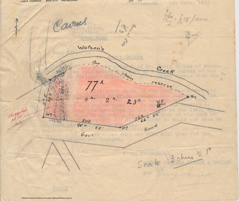
Booklet - Folder, Raynes Dickson Kiddle & Briggs Solicitors et al, Clintons Road, Christmas Hills, 1934-1938
Correspondence over a four year period (probably an incomplete file) on the behalf of Henry Cairns of Moonee Ponds and property owner at Christmas Hills / Watsons Creek including copy of a survey of his land title in relation to complaint regarding the Shire of Eltham encroaching on his land to make a road and subsequent purchase of land. The road provided acccess to the property of Mr W. Clinton of Heidelberg and other properties at Christmas Hills. Note by H.G. indicates that the property discussed in file is Clintons Road (not stated in file), possibly named after 1938. In December 1937 Eltham Shire Council agreed to purchase a block of land at the intersection of the Christmas Hills -- Smiths Gully roads from Mr Cairns to provide an outlet for the road which ran through the Cairns property. In March 1928 Mr Clinton had previously offered to contribute a sum of money towards the cost of purchasing the Cairns block to permit the road to go into his property was intending to transfer the property to himself. A Councilor was reported as being astounded in The Advertiser, 11 March 1938, as the land was needed for a road. Cr Baird: "The road was only to help his sports" Mr W. E. Clinton (Bill) was one of the founders of the Rob Roy Hill climb which took place at his property at Christmas Hills. He owned a garage in Heidleberg (See: https://cv.vic.gov.au/stories/sporting-life/speed-style-spirit-the-rob-roy-hillclimb/the-rob-roy-hillclimb/)16 pieces of paperraynes dickson kiddle & briggs solicitors, henry cairns, shire of eltham, roadworks, christmas hills, watsons creek, w. e. clinton, clintons road, rob roy climb -
 Falls Creek Historical Society
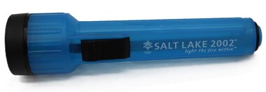
Souvenir - Salt Lake City Torch, 2002
This item is from the private collection of George Shirling of Red Onion, Falls Creek. XIX Olympic Winter Games were held in Salt Lake City from 8th to 24th 2002. Australia sent a team of 27 athletes to these Games and became the first Southern Hemisphere country to win gold medals at the Winter Olympics. They were won by Steven Bradbury in the 1,000m short track speed skating followed by Alisa Camplin in aerial skiing. Adrian Costa from Falls Creek was competing at his fourth Olympics and carried the Australian flag in the Opening Ceremony. George Shirling arrived in Falls Creek in 1962. He engaged Phil Nowell to build the original Koki Alpine Lodge which opened in 1965 with 14 beds. George operated the lodge with Michael “Baldy” Blackwell as manager. He also graduated in sport psychology in 1981 and was invited to become team psychologist for the Australian Winter Olympic team which went to Albertville, France, in 1992. He later owned the Red Onion Chalet. George credited the success of Koki to “Baldy” Blackwell. “Baldy” and Phil Nowell started the Trackers Mountain Lodge in partnership during the 1980s. In 1971 George sold Koki Lodge to Sigi Doerr. In 2024 the renamed Koki Alpine resort remains a highly popular destination in Falls Creek. George Shirling passed away on 27th February 2023. He had remained actively involved in Falls Creek and was generous with his time and knowledge, always an amazing supporter of The Falls Creek Museum and Falls Creek Village.This item is significant because it demonstrates George Shirling's ongoing connection to the Olympic Movement. A blue and black torch purchased as a souvenir from the Salt Lake City Winter Olympics. It bears the Salt Lake City Winter Olympics Logo and motto in white text on one side.SALT LAKE 2002 light the fire within george shirling, salt lake city 2002 -
 Falls Creek Historical Society
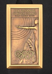
Medal - Olympic Winter Games Salt Lake 2002 volunteer medal
This item is from the private collection of George Shirling of Red Onion, Falls Creek. XIX Olympic Winter Games were held in Salt Lake City from 8th to 24th 2002. Australia sent a team of 27 athletes to these Games and became the first Southern Hemisphere country to win gold medals at the Winter Olympics. They were won by Steven Bradbury in the 1,000m short track speed skating followed by Alisa Camplin in aerial skiing. Adrian Costa from Falls Creek was competing at his fourth Olympics and carried the Australian flag in the Opening Ceremony. George Shirling arrived in Falls Creek in 1962. He engaged Phil Nowell to build the original Koki Alpine Lodge which opened in 1965 with 14 beds. George operated the lodge with Michael “Baldy” Blackwell as manager. He also graduated in sport psychology in 1981 and was invited to become team psychologist for the Australian Winter Olympic team which went to Albertville, France, in 1992. He later owned the Red Onion Chalet. George credited the success of Koki to “Baldy” Blackwell. “Baldy” and Phil Nowell started the Trackers Mountain Lodge in partnership during the 1980s. In 1971 George sold Koki Lodge to Sigi Doerr. In 2024 the renamed Koki Alpine resort remains a highly popular destination in Falls Creek. George Shirling passed away on 27th February 2023. He had remained actively involved in Falls Creek and was generous with his time and knowledge, always an amazing supporter of The Falls Creek Museum and Falls Creek Village.This medal is significant because it represents Australia's involvement in the Winter Olympics Salt Lake City 2002.A rectangular medal presented for participation by volunteers at Salt Lake City Winter Olympics 2002. The front of the medal depicted three athletes emerging from a mountain, with the Olympic Rings below. The reverse featured the Delicate Arch, the Olympic Rings and logo, and a mountain range in the background. On Front: XIX OLYMPIC WINTER GAMES SALT LAKE 2002 On Reverse: 7 - 16 MARCH 2002/ MIND BODY SPIRITgeorge shirling, salt lake city 2002, adrian costa -
Frankston RSL Sub Branch
Drift Recorder, W & G, A M Drift Recorder MKII, 1930 - 1939
Purpose built mechanical calculation machine for determining the drift of aircraft when operating in crosswind conditions. This device has an eyepiece and a prismatic periscope for viewing a distant feature being tracked. This device has calibrated rotary scales for height, speed (in KNOTS and MPH), and an adjustment to preset the 'crab angle' of the aircaft for cross wind compensation. The device can be opened for cleaning or maintenance purposes. Refer to the following extracts for information about bomb drift: "Crosswinds brought into the bombing problem a new factor, "drift" In order to fly a given ground track in a crosswind, an aircraft had to "crab" into the wind; the angle formed between the aircraft's true heading and its ground track was called the "drift angle" In a crosswind, the bomb would impact directly behind the aircraft and along its longitudinal axis at the moment of release. But this meant that the bomb would strike the ground at some point downwind of the aircraft's ground track. Thus, in order to score a hit, the bomber had to fly a ground track that ran upwind of the target." "Air resistance acting on a bomb after release caused it to lag behind the drop point and hit somewhere behind the bomber. The distance from a point beneath the aircraft at the instant of bomb impact to the point of bomb impact was called "trail." Trail increased as the bomber's airspeed increased or as its altitude increased. Furthermore, since different bombs encountered different resistance in the air, trail was also a factor of bomb shape."A. M. Drift Recorder MKII REF. No 6B/190 No 2668/41 X/ 3606 3E4H28 -
 Mission to Seafarers Victoria
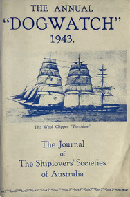
Journal (item) - Periodicals-Annual, Shiplovers' Society of Victoria, The Annual Dog Watch, 1943
This journal provides the reader with glimpses of the adventures and hardships of a seaman's life. Many of the stories are of sailing ships.First issue of the magazine published during the war Contributes to our knowledge of the importance of shipping and places on record those stories of the sea which would otherwise be lost.sailing ships, steamships, shipping, seafaring life, shiplovers' society of victoria, dog watch, ww2, hms jervis bay -
 Whitehorse Historical Society Inc.
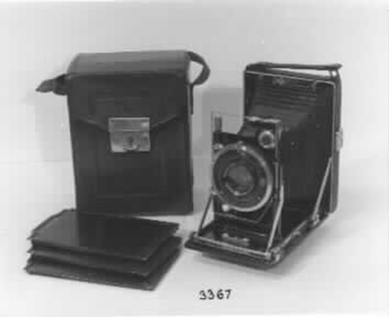
Functional object - Camera & Accessories, c1920
History prior to 1946 unknown. Camera etc was purchased by the donor in 1946 from Herbert Small Camera Supply then in Elizabeth Street Melbourne. Donor used camera regularly until recent years.'Etue' folding camera with accessories (camera, case, 3 negative containers in a imitation leather & cardboard container) and an additional slide tray. Camera can be used with glass plates, cut negative film and film packs. When camera is opened the lens, bellows etc slide into position. The whole lot slides on a rail system and can be locked in the position required. Item to be photographed can be viewed in a viewfinder which can be turned to a horizontal or vertical plane. In the viewfinder has a small bubble level. It includes an oblong chrome wire which is used to set the minimum distance from lens to object.|Camera is of steel covered and is covered with leather with a carrying handle. provision is made in the back to carry a film slide in a small envelope style pocket|Camera is made by Kamera Werkstatten of Dresden c1920.|It has a 'Zeiss Tessar' 1:4.5 lens of 10.5 cm focal length. Shutter is a 'Compur' with speeds of 1 to 1/250th of a second with Bulb and Time. It also has a delayed action feature. It also has a double extension for close up studies.|When folder it is a mere 4.5 cm from front to back, which cause it to be advertised as the slimmest camera made.|Camera case is made of brown tooled leather with a chrome clip and adjustable carrying handle - lid open upwards for the camera .Case is lined with a purple type of velvet material. 10 Items in total.photography, cameras, camera accessories -
 Bendigo Historical Society Inc.
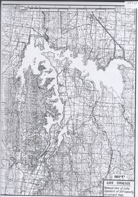
Map - Laminated map of Lake Eppalock at full capacity. Map 'E'
John Perry Collection. Laminated map of Lake Eppalock at full capacity. Black and white. The dam was built by the State Rivers and Water Supply Commission of Victoria. The dam wall height is 45 metres (148 ft) and the main embankment is 1,041 metres (3,415 ft) long. At 100% capacity the dam wall was designed to hold back 304,651 megalitres (6.7014×10¹⁰ imp gal; 8.0480×10¹⁰ US gal) of water. The surface area of Lake Eppalock is 3,011 hectares (7,440 acres) and the catchment area is 2,124 square kilometres (820 sq mi). The controlled spillway is capable of discharging 8,040 cubic metres per second (284,000 cu ft/s). Lake Eppalock supplies both stock and domestic water to the Campaspe irrigation district. It also serves as a water supply to Bendigo and Heathcote and, in more recent times, Ballarat. The lake is a major attraction for those engaging in watersports, with a number of tourist parks and accommodation facilities available. Permissible activities on the lake include high-speed boating, water skiing, sailing, canoeing, fishing and swimming. The lake's water levels were low for approximately eight years between 2002 and 2010 during a prolonged drought, which restricted the amount of recreational activity until rainfall in the latter half of 2010 returned the lake to 100 percent capacity. Built between 1961 and 1964, Lake Eppalock remains the only water storage on the Campaspe River system.map, eppalock, water, dam, reservoir -
 Lilydale RSL Sub Branch
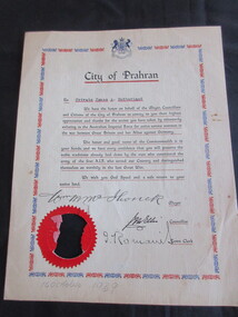
Certificate - Certificate of Appreciation, 16-110-1939
Private James Andrew Sutherland - VX59088 ,POW - Thailand (Burma Railway) and Changi.Paper certificate with "City of Prahran" as heading with Australian Coat of Arms. Blue and red border.To Private James A Sutherland. We have the honour on behalf of the Mayor, Councilors and Citizens of the City of Prahran to convey to you their highest appreciation and thanks for the action you have taken by voluntarily enlisting in the Australian Imperial Force for active service overseas in the war between Great Britain and her Allies against Germany. The honour and good name of the Commonwealth is in your hands, and we have every confidence that you will preserve the noble traditions already laid down by the men who constituted the Army of the first A.I.F. who served our country and distinguished themselves so worthily in the last Great War. We wish you God speed and a safe return to your Native land. Signed Wm M McIlwrick Mayor, J M Ellis Councilor and J Romaiu Town Clerk.