Showing 1168 items matching "device"
-
 Kew Historical Society Inc
Photograph - Rural landscape, c.1926
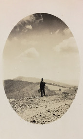
Henry Beater Christian (1886-1962) , was a descendant of one of the earliest settler families in Kew. Employed at the Kew Asylum as a 'public servant', he was a skilled amateur photographer, photographing numerous scenes in Kew and on his travels around Victoria. The majority of his photographs date from 1916 to 1929. His finest photographs are housed in two photograph albums. Digital copy of a photograph from page 17 of the 47-page photograph album containing 261 gelatinous silver images, loaned by Diane Washfold with permission given to digitise and hold a copy in our collection. This photograph, dating from c.1926, forms part of a group of photos preceding images of [Black] Spur, so the photographs may have been taken as part of that bushwalking trip. John Chapman has written in 'Bushwalking Clubs - A Brief History', about the establishment in Victoria of the first bushwalking club in 1888, and the popularisation of bushwalking during the interwar period. Henry Christian's 'walks' appear to have been undertaken solely or with a companion/s. This camera shot invites the viewer to access the landscape through the point-of-view of the man standing with his back to the camera at the edge of the road. The man holds leaves in his left hand [to deter insects], and has a knapsack on his back. The landscape in the distance includes both cleared land for farming and remnant vegetation. The oval framing device was used when Henry Christian developed the photo.Illegible ink inscription on pagehenry beater christian (1886-1962), landscape photography, kew (vic.) — yarra river, christian-washfold collection, photograph albums, bushwalking -- victoria -
 Flagstaff Hill Maritime Museum and Village
Tool - Auger Bit, William A Ives, 1860-1950
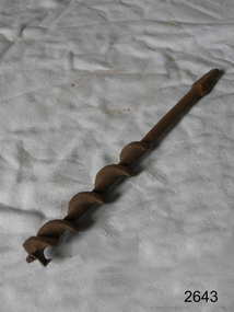
William A Ives worked in New Haven, Connecticut, and surrounding towns of Wallingford and Hamden from 1868 to 1917 and was a prolific inventor of braces and other wood boring tools between 1868 and 1884, when he received a dozen patents for these devices. William A. Ives lived in the New Haven CT area, and his first auger-making activity took place in the town of Hamden. At first in association with the Churchill family who had been manufacturing tools in the area at least as early as 1863. That firm's works had created "Augerville" in Hamden, starting earlier, possibly as early as 1830. Ives became active as part of the Hamden Manufacturing Co. until 1875 (it is thought he may also have started his own business in the interim), and the William A. Ives & amp; Co. was established by 1877. This continued, until William's death in 1888, when The Hamden Mfg. Company became its successor. Ives also registered the name "Mephisto" trademark name with the US patent office that was to be used in connection with augers, auger bits, machine bits as of June 1st, 1909, appearing on items up until at least 1922. It also appears that the trademark was licensed by the Mephisto Tool Co of Hudson New York who continued to manufacture tools under this trademark. Item is significant because its maker was the inventor of the wood auger boring bit and his patent has been used ever since on many different types of bits with little change to the original design.Auger wood screw bit W A Ives Patent Noneflagstaff hill, warrnambool, shipwrecked-coast, flagstaff-hill, flagstaff-hill-maritime-museum, maritime-museum, shipwreck-coast, flagstaff-hill-maritime-village -
 Federation University Historical Collection
Book - Book - Handbook, VIOSH: Chemicals and the Artist; A health and safety handbook for students, teachers and artworkers by Bob Hall
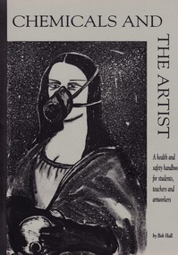
Victorian Institute of Occupational Safety and Health (VIOSH) Australia is the Asia-Pacific centre for teaching and research in occupational health and safety (OHS) and is known as one of Australia's leaders on the field. VIOSH has a global reputation for its innovative approach within the field of OHS management. VIOSH had its first intake of students in 1979. At that time the Institution was known as the Ballarat College of Advanced Education. In 1990 it became known as Ballarat University College, then in 1994 as University of Ballarat. It was 2014 that it became Federation University. VIOSH Australia students are safety managers, senior advisors and experienced OHS professionals. They come from all over Australia and industry. Students are taught active research and enquiry; rather than textbook learning and a one-size fits all approach. VIOSH accepts people into the Graduate Diploma of Occupational Hazard Management who have no undergraduate degree - on the basis of extensive work experience and knowledge. Book outlines the requirements to be considered - chemicals, conditions re ventilation, protective clothing such as respiratory devices, gloves and eye and face protectors. An understanding of the effects of various chemical solutions. A detailed Glossary of health and safety terms is included. Alternative options for solvents etc is also given. The importance of a safety hazard audit register for hazardous substances is detailed. Glued and cloth bound book of 161 pages. Cover light fawn with black print and binding.viosh, safety and health, victorian institute of occupational safety and health, art facilities, chemicals, ventilation, safety audits, hazardous chemicals and substances, protective clothing, bob hall -
 City of Moorabbin Historical Society (Operating the Box Cottage Museum)
Bandage, cotton, mid 20thC
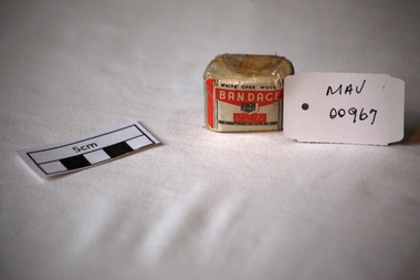
A bandage is a piece of material used either to support a medical device such as a dressing or splint, or on its own to provide support to the body; it can also be used to restrict a part of the body. G. J. Coles opened the 'Coles Variety Store' on 9 April 1914 on Smith Street in the Melbourne, Victoria suburb of Collingwood. Further expansion occurred and Coles' interest in food retailing was spurred in 1958 when it acquired 54 John Connell Dickins grocery stores. It then acquired the Beilby's chain in South Australia in 1959 and 265 Matthews Thompson grocery stores in New South Wales in 1960 .In 1960, the first supermarket was opened in the Melbourne suburb Balwyn North, at the corner of Burke and Doncaster Roads where a modernised version continues to operate. By 1973, Coles had established stores in all Australian capital cities. From 1962, its supermarkets were branded Coles New World with accompanying rocket imagery. In 1991, the stores were re-branded Coles Supermarkets and from 1998, simply as Coles. George James (G. J.) Coles learned the retail trade working for his father's 'Coles Store' business from 1910 to 1913. The store continued operating as "The Original Coles" at Wilmot, Tasmania until it was destroyed by a fire on 24 January 2014. An unused, 1 inch ( 2.5cm ) x 6 yards ( 2metres) cotton, ‘open wove’ bandage in a cellophane wrapper sold by G.J. Coles Pty Ltd Variety StoresCellophane wrapper top: WHITE OPEN WOVE / BANDAGE / 1 X 6 YDS. / SPECIAL QUALITY / G.J.COLES * pharmacy, medicines, bandages, wounds, early settlers, market gardeners, moorabbin, bentleigh, cheltenham, cotton, gauze, coles g j pty ltd., variety stores, supermarkets, smith street collingwood, retailers, shops -
 Flagstaff Hill Maritime Museum and Village
Instrument - Mariner's astrolabe
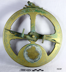
This representative example demonstrates a mariner’s astrolabe. Historical examples are rare. There are less than one hundred known to exist and most of these have been recovered from shipwrecks, many from Spanish and Portuguese vessels. An astrolabe is a measuring device once used to navigate the seas by observing the sun and stars to measure their altitude. The measurement of altitude could then be used to calculate the ship’s latitude but at that time in history there was no means of measuring longitude. The body of the navigational astrolabe was cast brass and much heavier, and less complicated than the variety used on land. The heavier weight and cut-away shape reduced the effect of the wind and waves when trying to use it at sea. A mariner’s astrolabe or ‘star finder’ is a simplified version than that used by Arabic astronomers to find the altitude of the sun and stars above the horizon, and time of the sunrise and sunset. It is a forerunner to the quadrant, octant and sextant and was popular for about 200 years over the 1500s and 1600s to find the latitude of a ship at sea. The user held the astrolabe at eye level and, usually with assistance, aligned the stars through the two small sights (pinnules), then read the altitude indicated by the pointer on the arm. It could also be used to sight the sun by holding it lower down, aiming it at the sun, and adjusting it until the sun shone through both pinnules. This astrolabe is an example used to demonstrate the mariner’s astrolabe, which was navigational tool of the 1500s and 1600s, in the time before longitude was able to be determined. It is a forerunner to modern navigation technology. Mariner’s astrolabe – a representative example. A gold painted, disc shaped object with cut outs and revolving arm in centre. The arm has two sights attached at right angles. The top has a ring attached. Measurements are marked in degrees in a circular scale around outer edge.flagstaff hill, warrnambool, maritime village, maritime museum, flagstaff hill maritime museum & village, shipwreck coast, great ocean road, navigation instrument, navigation tool, navigation, astrolabe, mariner’s astrolabe, measure latitude, measure altitude, arabic navigation, measuring device, star finder, astronomy, marine tool, marine instrument -
 Moorabbin Air Museum
Equipment (item) - Graviscope for Lincoln (Australian) RAAF Ident No G6C/3972, Graviscope for Lincoln
Description White plastic doubled sided Graviscope stored in protective leather carry case. Case is fitted with pair of press studs, pocket in front for holding instructions and is stamped "Graviscope / for / Lincoln / (Australian) / Manufactured by / Melb > W & G < Aust / R.A.A.F / Ident. No G6C/3972". Plastic graviscope consists of a 277mm white disc, printed on both sides, overlaid on one side by a 224mm disc and the other side by a 175mm disc. All discs located by central screw, to which is attached a 160mm long x 25mm wide clear celluloid strip. History / Summary The graviscope is a computing device, which in aircraft was used for measuring the centre of gravity in an aircraft. This would vary depending on crew, bomb load, fuel and stores carried. It was used in the British designed but Australian manufactured, Government Aircraft Factory (GAF) Lincoln heavy bomber, which was operated by the Royal Australian Air Force (RAAF) in the years following the Second World War. This aircraft was originally a derivative of the famous Avro Lancaster bomber. The Lincoln was used by both the RAAF and the Royal Air Force in operations against Malayan Communist terrorists during the Malayan Emergency, 1948-1960. This graviscope is of the type designed for and used by RAAF and RAF aircrew who operated this aircraft.Many by W and G Australia -
 Puffing Billy Railway
Equipment - Flaman Speed Indicator and Recorder transport Box
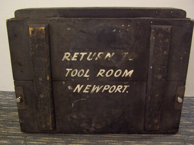
Train Instrument transportation Box used for the transporting of Flaman Speed Indicator and Recorder to the repair workshops The Flaman Speed Indicator and Recorder was a device patented in 1901 by Nicolas Charles Eugène Flaman of France for indicating the current speed of a vehicle (for example a railway locomotive) and recording it on a paper tape that could be unrolled and examined at the end of a run to provide evidence of the speeds attained on the journey. Design features: The paper tape recording was driven directly by the wheels of the locomotive, with the paper spool moving at a fixed rate per kilometre travelled. Three graphs were recorded, the first being time elapsed (with the trace moving vertically if the train was stationary), the second being a speed curve. and the third recording the driver's attentiveness to signals ("Vigilance") by marking one tick above a line when the driver depressed a button, and another below the line when the engine went over the signal ramp. Data recorded: Read together, it was possible to determine exactly what speed the locomotive had been travelling at any point in time or distance. As well as allowing study of locomotive performance, it also allowed greater scrutiny of the observance of the driver of speed restrictions along the line and attentiveness to signals. It was practice on some railways such as the Victorian Railways in Australia for the driver to sign the speed chart prior to departure.Historic - Victorian Railways - Train Instrument transportation Box for the transporting of Flaman Speed Indicator and Recorder to the repair workshopsLarge wooden box with wrought iron fittings, painted black with white lettering on side panels. RETURN TO / TOOL ROOM / NEWPORTpuffing billy, train instrument transportation box, victorian railways, flaman speed indicator and recorder -
 Department of Energy, Environment and Climate Action
Relative Humidity Meter
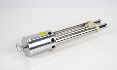
Bushfire behaviour is influenced by many factors including temperature, relative humidity (RH), forest type, fuel quantity and fuel dryness, topography and even slope. Wind has a dominant effect on the Rate of Spread (ROS), as well as fire size, shape and direction. Temperature and relative humidity have major impacts on fuel dryness and therefore upon the availability of fuel for combustion. The amount of fine fuel available can increase rapidly from nearly zero when fuel moisture content is more than 16% after rain or a heavy morning dew, to many tonnes per hectare as fuel dries out later in the day and the moisture content drops below 9%. This explosive escalation in the amount of available fuel can happen over a few hours on hot and windy days. This device is used for determining air temperature and relative humidity. It contains two thermometers, one of which is covered with a wick saturated with ambient temperature liquid water. These two thermometers are called dry bulb and wet bulb. Once the thermometers to reach equilibrium temperatures the two thermometers are quickly read. The figures are then used to convert the dry bulb temperature TDB and the wet bulb temperature TWB into humidity information. The wet bulb temperature is approximately equal to the adiabatic saturation temperature. Relative humidity meter in wooden box two stainless steel tubes contain wet and dry thermometers A small clock drives a fan motor in the base to circulate airforests commission victoria (fcv), weather, bushfire -
 The Beechworth Burke Museum
Photograph - Lantern Slide, c1900
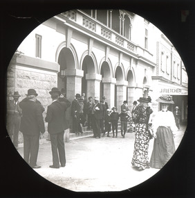
This image depicts people walking down the street in the early 1900s, giving a glimpse into everyday life of the Edwardian era in rural Australia. The image also captures the Beechworth Post Office, located on the corner of Ford and Camp Streets. The stone post office building was built in 1858 to replace the inadequate wooden building on the same location. It was built from granite sourced from the area and features Architectual designs of the era including a hipped slate roof and a colonnaded entrance surmounted by a parapet. Lantern slides, sometimes called 'magic lantern' slides, are glass plates on which an image has been secured for the purpose of projection. Glass slides were etched or hand-painted for this purpose from the Eighteenth Century but the process became more popular and accessible to the public with the development of photographic-emulsion slides used with a 'Magic Lantern' device in the mid-Nineteenth Century. Photographic lantern slides comprise a double-negative emulsion layer (forming a positive image) between thin glass plates that are bound together. A number of processes existed to form and bind the emulsion layer to the base plate, including the albumen, wet plate collodion, gelatine dry plate and Woodburytype techniques. Lantern slides and magic lantern technologies are seen as foundational precursors to the development of modern photography and film-making techniquesThis glass slide is significant because it provides insight into Beechworth's social amenities and religious infrastructure in the late Nineteenth Century. It is also an example of an early photographic and film-making technology in use in regional Victoria in the time period.Thin translucent sheet of glass with a square image printed on the front and framed in a black backing. It is held together by metals strips to secure the edges of the slide.burke museum, beechworth, lantern slide, slide, glass slide, plate, burke museum collection, photograph, monochrome, 1900s, edwardian era, architecture, granite building -
 Flagstaff Hill Maritime Museum and Village
Audio - Gramophone Cylinder, B & H Jack, 1907
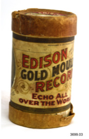
Edison Records was one of the early record labels that pioneered sound recording and reproduction, and was an important player in the early recording industry. The first phonograph cylinders were manufactured in 1888, followed by Edison's foundation of the Edison Phonograph Company in the same year. The recorded wax cylinders, later replaced by Blue Amberol cylinders, and vertical-cut Diamond Discs, were manufactured by Edison's National Phonograph Company from 1896 on, reorganized as Thomas A. Edison, Inc. in 1911. Until 1910 the recordings did not carry the names of the artists. The company began to lag behind its rivals in the 1920s, both technically and in the popularity of its artists, and halted production of recordings in 1929. Thomas A. Edison invented the phonograph, the first device for recording and playing back sound, in 1877. After patenting the invention and benefiting from the publicity and acclaim it received, Edison and his laboratory turned their attention to the commercial development of electric lighting, playing no further role in the development of the phonograph for nearly a decade. Start of the Recording Industry: In 1887, Edison turned his attention back to improving the phonograph and the phonograph cylinder. The following year, the Edison company introduced the ”Perfected Phonograph”. Edison introduced wax cylinders approximately 4+1⁄4 inches (11 cm) long and 2+1⁄4 inches (5.7 cm) in external diameter, which became the industry standard. They had a maximum playing time of about 3 minutes at 120 RPM, but around the turn of the century the standard speed was increased to (first 144) and then 160 RPM to improve clarity and volume, reducing the maximum to about 2 minutes and 15 seconds. Several experimental wax cylinder recordings of music and speech made in 1888 still exist. The wax entertainment cylinder made its commercial debut in 1889 at first, the only customers were entrepreneurs who installed nickel-in-the-slot phonographs in amusement arcades, saloons and other public places. At that time, a phonograph cost the equivalent of several months' wages for the average worker and was driven by an electric motor powered by hazardous, high-maintenance wet cell batteries. After more affordable spring-motor-driven phonographs designed for home use were introduced in 1895, the industry of producing recorded entertainment cylinders for sale to the general public began in earnest. Blank records were an important part of the business early on. Most phonographs had or could be fitted with attachments for the users to make their own recordings. One important early use, in line with the original term for a phonograph as a "talking machine", was in business for recording dictation. Attachments were added to facilitate starting, stopping, and skipping back the recording for dictation and playback by stenographers. The business phonograph eventually evolved into a separate device from the home entertainment phonograph. Edison's brand of business phonograph was called the Ediphone. The collection of three phonograph cylinders are an example of early recorded music use for domestic entertainment. They are significant as they represent the beginnings of the modern recording industry.Cardboard tube-shaped gramophone cylinder box with lid. The printed label on the outside of the box advertises the maker and patent details. The Catalogue Number and Title are either printed or hand written on the cylinder’s lid. This cylinder contained Record no. 49, “B & H Jack” and was made at the Edison Laboratory USA. C. 1905On lid “Edison Record No. 49”, written in pencil “B & H Jack” (it looks like this) On cylinder “EDISON GOLD MOULDED RECORDS ECHO ALL OVER THE WORLD” Patents listed for 1904 & 1905warrnambool, flagstaff hill maritime museum, maritime museum, shipwreck coast, flagstaff hill maritime village, gramophone record, gramophone cylinder, edison cylinder, edison record, home entertainment, music recording, edison laboratory orange nj, usa, national phonograph company of australia ltd sydney, thomas a. edison -
 Flagstaff Hill Maritime Museum and Village
Audio - Gramophone Cylinder, National Phonograph Co, Poor old England, 1908
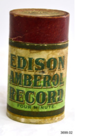
Edison Records was one of the early record labels that pioneered sound recording and reproduction, and was an important player in the early recording industry. The first phonograph cylinders were manufactured in 1888, followed by Edison's foundation of the Edison Phonograph Company in the same year. The recorded wax cylinders, later replaced by Blue Amberol cylinders, and vertical-cut Diamond Discs, were manufactured by Edison's National Phonograph Company from 1896 on, reorganized as Thomas A. Edison, Inc. in 1911. Until 1910 the recordings did not carry the names of the artists. The company began to lag behind its rivals in the 1920s, both technically and in the popularity of its artists, and halted production of recordings in 1929. Thomas A. Edison invented the phonograph, the first device for recording and playing back sound, in 1877. After patenting the invention and benefiting from the publicity and acclaim it received, Edison and his laboratory turned their attention to the commercial development of electric lighting, playing no further role in the development of the phonograph for nearly a decade. Start of the Recording Industry: In 1887, Edison turned his attention back to improving the phonograph and the phonograph cylinder. The following year, the Edison company introduced the ”Perfected Phonograph”. Edison introduced wax cylinders approximately 4+1⁄4 inches (11 cm) long and 2+1⁄4 inches (5.7 cm) in external diameter, which became the industry standard. They had a maximum playing time of about 3 minutes at 120 RPM, but around the turn of the century the standard speed was increased to (first 144) and then 160 RPM to improve clarity and volume, reducing the maximum to about 2 minutes and 15 seconds. Several experimental wax cylinder recordings of music and speech made in 1888 still exist. The wax entertainment cylinder made its commercial debut in 1889 at first, the only customers were entrepreneurs who installed nickel-in-the-slot phonographs in amusement arcades, saloons and other public places. At that time, a phonograph cost the equivalent of several months' wages for the average worker and was driven by an electric motor powered by hazardous, high-maintenance wet cell batteries. After more affordable spring-motor-driven phonographs designed for home use were introduced in 1895, the industry of producing recorded entertainment cylinders for sale to the general public began in earnest. Blank records were an important part of the business early on. Most phonographs had or could be fitted with attachments for the users to make their own recordings. One important early use, in line with the original term for a phonograph as a "talking machine", was in business for recording dictation. Attachments were added to facilitate starting, stopping, and skipping back the recording for dictation and playback by stenographers. The business phonograph eventually evolved into a separate device from the home entertainment phonograph. Edison's brand of business phonograph was called the Ediphone. The collection of three phonograph cylinders are an example of early recorded music use for domestic entertainment. They are significant as they represent the beginnings of the modern recording industry.Cardboard tube-shaped gramophone cylinder box with lid. The printed label on the outside of the box advertises the maker and patent details. The Catalogue Number and Title are either printed or hand written on the cylinder’s lid. This cylinder contained Record no. 13619, the recording “Poor old England” published by Castling and Godfrey, sung by Billy Williams. Made by National Phonograph Company USA. C.1907On lid “Edison Record” and “This record should turn at 160 revolutions per minute, no faster” Written on lid in blue pen “Trumpet”, “EDISON AMBEROL RECORD / FOUR MINUTE”warrnambool, flagstaff hill maritime museum, maritime museum, shipwreck coast, flagstaff hill maritime village, gramophone record, gramophone cylinder, edison cylinder, edison record, home entertainment, music recording, edison laboratory orange nj, usa, national phonograph company of australia ltd sydney, thomas a. edison -
 Flagstaff Hill Maritime Museum and Village
Audio - Gramophone Cylinder, Sandy McNab, 1908
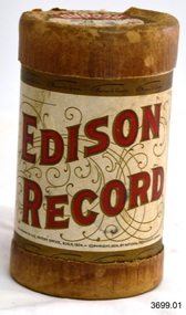
Edison Records was one of the early record labels that pioneered sound recording and reproduction, and was an important player in the early recording industry. The first phonograph cylinders were manufactured in 1888, followed by Edison's foundation of the Edison Phonograph Company in the same year. The recorded wax cylinders, later replaced by Blue Amberol cylinders, and vertical-cut Diamond Discs, were manufactured by Edison's National Phonograph Company from 1896 on, reorganized as Thomas A. Edison, Inc. in 1911. Until 1910 the recordings did not carry the names of the artists. The company began to lag behind its rivals in the 1920s, both technically and in the popularity of its artists, and halted production of recordings in 1929. Thomas A. Edison invented the phonograph, the first device for recording and playing back sound, in 1877. After patenting the invention and benefiting from the publicity and acclaim it received, Edison and his laboratory turned their attention to the commercial development of electric lighting, playing no further role in the development of the phonograph for nearly a decade. Start of the Recording Industry: In 1887, Edison turned his attention back to improving the phonograph and the phonograph cylinder. The following year, the Edison company introduced the ”Perfected Phonograph”. Edison introduced wax cylinders approximately 4+1⁄4 inches (11 cm) long and 2+1⁄4 inches (5.7 cm) in external diameter, which became the industry standard. They had a maximum playing time of about 3 minutes at 120 RPM, but around the turn of the century the standard speed was increased to (first 144) and then 160 RPM to improve clarity and volume, reducing the maximum to about 2 minutes and 15 seconds. Several experimental wax cylinder recordings of music and speech made in 1888 still exist. The wax entertainment cylinder made its commercial debut in 1889 at first, the only customers were entrepreneurs who installed nickel-in-the-slot phonographs in amusement arcades, saloons and other public places. At that time, a phonograph cost the equivalent of several months' wages for the average worker and was driven by an electric motor powered by hazardous, high-maintenance wet cell batteries. After more affordable spring-motor-driven phonographs designed for home use were introduced in 1895, the industry of producing recorded entertainment cylinders for sale to the general public began in earnest. Blank records were an important part of the business early on. Most phonographs had or could be fitted with attachments for the users to make their own recordings. One important early use, in line with the original term for a phonograph as a "talking machine", was in business for recording dictation. Attachments were added to facilitate starting, stopping, and skipping back the recording for dictation and playback by stenographers. The business phonograph eventually evolved into a separate device from the home entertainment phonograph. Edison's brand of business phonograph was called the Ediphone. The collection of three phonograph cylinders are an example of early recorded music use for domestic entertainment. They are significant as they represent the beginnings of the modern recording industry.Cardboard tube-shaped gramophone cylinder box with lid. The printed label on the outside of the box advertises the maker and patent details. The Catalogue Number and Title are either printed or hand written on the cylinder’s lid. This cylinder was made by Edison 1908 and contains Record number 53 by Sandy McNab. c. 1908On label “Edison Record No. 53, Sandy McNab" and "Form no. 1130, April 1908. Patented December 6 1904, No. 2109, and December 6 1904 No. 2110. “This record is sold by the National Phonograph Company of Australia Ltd, at Sydney Australia.” Trade Mark Thomas A. Edison warrnambool, flagstaff hill maritime museum, maritime museum, shipwreck coast, flagstaff hill maritime village, gramophone record, gramophone cylinder, edison cylinder, edison record, home entertainment, music recording, edison laboratory orange nj, usa, national phonograph company of australia ltd sydney, thomas a. edison -
 Flagstaff Hill Maritime Museum and Village
Equipment - Lifebuoy, Loch Ness, 1869-1909
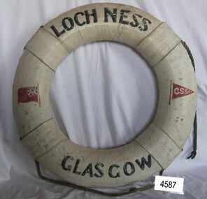
This lifebuoy bears the name of the ship, its origin, the shipping company and the red ensign. These details mean that the lifebuoy was part of the lifesaving equipment on the sailing ship the Loch Ness, part of the Glasgow Shipping Company’s Loch Line (G.S.C. on the red pennant) and a British-registered ship (the red flag with the Union Jack on it). Lifebuoys were part of the emergency lifesaving equipment carried on vessels in the late 19th and early 20th century. The ring was made of strips of cork wood joined together to make the ring shape then covered in canvas and sealed usually with white paint. Four evenly spaced canvas reinforcing bands would be added for strength and for a place to thread a rope or line. A lifebuoy, or life-preserver, is used as a buoyancy device often thrown to an endangered or distressed person in the water to keep them afloat while they receive help. It is usually connected by a rope to a person in a safe area such a nearby vessel or on shore. Lifebuoys is a made from a buoyant materials such as cork or foam and ae usually covered with canvas for protection and to make it easy to grip. The first use of life saving devices in recent centuries was by the Nordic people, who used light weight wood or cork blocks to keep afloat. Cork lifebuoys were used from the late 19th to early 20th century. Kapok fibre was then used as a filling for buoys but wasn’t entirely successful. Light weight balsa wood was used as a filler after WW1. In 1928 Peter Markus invented and patented the first inflatable life-preserver. By WW2 foam was combined with Kapok. Laws were passed over time that has required aeroplanes and water going-vessels to carry life-preservers on board. The ship LOCH NESS 1869-1922 … The ship Loch Ness, of Glasgow, was the same ship what William Carmichael sailed on to Australia when he laid the commemoration stone on behalf of his sister Eva and himself, dedicated to their parents, brothers and sisters. The family members lost their lives on June 1, 1878, when their ship, the Loch Ard, was wrecked at Mutton Bird Island in south west Victoria. Eva Carmichael was one of the two survivors from that shipwreck, the other 52 tragically lost their lives. The ship Loch Ness was a three-masted sailing ship built in 1869 for the Loch Line owned by the Glasgow Shipping Company. The line transported cargo and passengers from Glasgow, Scotland, to Australian ports. The Loch Ness was sold in 1908 to Stevedore & Shipping Co, Sydney for use as a coal hulk. In 1914 the Australian Government took over the ship for naval defence purposeless. In 1926 the ship was sunk during gunfire practice by the 1922 built, light cruiser HMAS Melbourne, near Fremantle, Western Australia. The lifebuoy is an example of equipment carried on vessels in the late 19th and early 20th century to help preserve life. There were many lives lost in Australia’s colonial period, particularly along the coast of South West Victoria. The lifebuoy is significant for its connection to the ship Loch Ness on which William Carmichael, brother of Eva Carmichael, travelled to lay a memorial to their parents and all of their other siblings who lost their lives in the Loch Ard disaster of 1878 near Peterborough, Victoria. Lifebuoy, round, cork filling inside canvas cover, painted white, with rope attached. Lifebuoy has printed name of vessel Loch Ness, Glasgow. Symbols of red flag with white initials G S Co. There is also a red ensign."LOCH NESS", "GLASGOW" "G S Co"flagstaff hill, warrnambool, shipwrecked-coast, flagstaff-hill, flagstaff-hill-maritime-museum, maritime-museum, shipwreck-coast, flagstaff-hill-maritime-village, loch ness, loch ard, william carmichael, eva carmichael, lifebuoy, glasgow sailing ship, loch ness of glasgow, life rings, safety ring, life-saving buoy, ring buoy, life preserver, personal floating device, floatation device, safety equipment, g s c, glasgow shipping company, hmas melbourne, cruiser melbourne -
 The Beechworth Burke Museum
Photograph - Lantern Slide, c1900
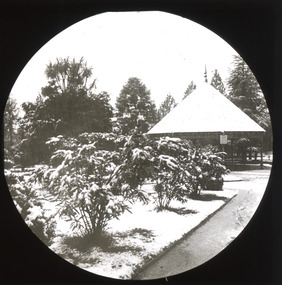
This image shows a pathway in the gardens adjacent to Beechworth's Town Hall at the beginning of the Twentieth Century, around the time of Australia's Federation. The pathway leading to a circular rotunda or covered seating area with a steep conical roof is lined with shrubs set in grass verges that appear to be covered with snow. It is unknown whether the snowfall or a factor to do with the gardens occasioned the taking of the image, which at the time may have been an exotic practice. Climate records going back to 1908 indicate that snow in winter is not unusual due to Beechworth's elevation and orientation, and the Town Hall itself was built in 1859. Lantern slides, sometimes called 'magic lantern' slides, are glass plates on which an image has been secured for the purpose of projection. Glass slides were etched or hand-painted for this purpose from the Eighteenth Century but the process became more popular and accessible to the public with the development of photographic-emulsion slides used with a 'Magic Lantern' device in the mid-Nineteenth Century. Photographic lantern slides comprise a double-negative emulsion layer (forming a positive image) between thin glass plates that are bound together. A number of processes existed to form and bind the emulsion layer to the base plate, including the albumen, wet plate collodion, gelatine dry plate and woodburytype techniques. Lantern slides and magic lantern technologies are seen as foundational precursors to the development of modern photography and film-making techniques. This glass slide is significant because it provides insight into Beechworth's social amenities and climate in the early Twentieth Century, around the time of Australia's Federation into one nation. It is also an example of an early photographic and film-making technology in use in regional Victoria in the time period. Thin translucent sheet of glass with a circular image printed on the front and framed in a black backing. It is held together by metals strips to secure the edges of the slide.burke museum, beechworth, lantern slide, slide, glass slide, plate, burke museum collection, photograph, monochrome, town hall, town hall gardens, snow, rotunda, magic lantern, indigo shire, north-east victoria, nineteenth century, 1900s, twentieth century, emulsion slides -
 The Beechworth Burke Museum
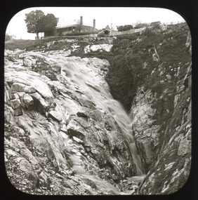
Photograph - Lantern Slide, c1900
This image shows the gorge adjacent to Beechworth in approximately 1900. Although the exact location of the photograph is yet to be determined, the present-day Beechworth Gorge Walk includes views of the Cascades at the point at which Spring Creek flows into the valley on the level below. Gold-sluicing techniques in use in the town during periods of active gold extraction may have altered the landscape since the photograph was taken, however. In the 1850s a mill was built at the top of the Spring Creek falls by Russian-born Louis Chevalier, brother of artist Nicholas Chevalier. The mill supplied the town with lumber that supported the town's initial construction boom. Lantern slides, sometimes called 'magic lantern' slides, are glass plates on which an image has been secured for the purpose of projection. Glass slides were etched or hand-painted for this purpose from the Eighteenth Century but the process became more popular and accessible to the public with the development of photographic-emulsion slides used with a 'Magic Lantern' device in the mid-Nineteenth Century. Photographic lantern slides comprise a double-negative emulsion layer (forming a positive image) between thin glass plates that are bound together. A number of processes existed to form and bind the emulsion layer to the base plate, including the albumen, wet plate collodion, gelatine dry plate and woodburytype techniques. Lantern slides and magic lantern technologies are seen as foundational precursors to the development of modern photography and film-making techniques.This glass slide is significant because it provides insight into Beechworth's built environment and natural landscape in the early Twentieth Century, around the time of Australia's Federation. It is also an example of an early photographic and film-making technology in use in regional Victoria in the time period.Thin translucent sheet of glass with a square image printed on the front and framed in a black backing. It is held together by metals strips to secure the edges of the slide.burke museum, beechworth, lantern slide, slide, glass slide, plate, burke museum collection, photograph, monochrome, indigo shire, north-east victoria, spring creek falls, beechworth gorge, louis chevalier, nicholas chevalier, lumber industry, timber industry, 1850s, construction, building, mill, mills, waterfall -
 The Beechworth Burke Museum
Photograph - Lantern Slide, c1900
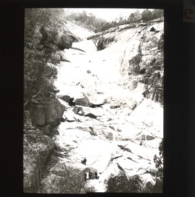
This image shows the gorge adjacent to Beechworth in approximately 1900. Although the exact location of the photograph is yet to be determined, the present-day Beechworth Gorge Walk includes views of the Cascades at the point at which Spring Creek flows into the valley on the level below. Gold-sluicing techniques in use in the town during periods of active gold extraction may have altered the landscape since the photograph was taken, however. In the 1850s a mill was built at the top of the Spring Creek falls by Russian-born Louis Chevalier, brother of artist Nicholas Chevalier. The mill supplied the town with lumber that supported the town's initial construction boom. Lantern slides, sometimes called 'magic lantern' slides, are glass plates on which an image has been secured for the purpose of projection. Glass slides were etched or hand-painted for this purpose from the Eighteenth Century but the process became more popular and accessible to the public with the development of photographic-emulsion slides used with a 'Magic Lantern' device in the mid-Nineteenth Century. Photographic lantern slides comprise a double-negative emulsion layer (forming a positive image) between thin glass plates that are bound together. A number of processes existed to form and bind the emulsion layer to the base plate, including the albumen, wet plate collodion, gelatine dry plate and woodburytype techniques. Lantern slides and magic lantern technologies are seen as foundational precursors to the development of modern photography and film-making techniques.This glass slide is significant because it provides insight into Beechworth's built environment and natural landscape in the early Twentieth Century, around the time of Australia's Federation. It is also an example of an early photographic and film-making technology in use in regional Victoria in the time period.Thin translucent sheet of glass with a square image printed on the front and framed in a black backing. It is held together by metals strips to secure the edges of the slide.burke museum, beechworth, lantern slide, slide, glass slide, plate, burke museum collection, photograph, monochrome, beechworth gorge, indigo shire, landscapes, mill, sluicing, gold mining, north-east victoria, spring creek, louis chevalier, cascades -
 Flagstaff Hill Maritime Museum and Village
Instrument - Scale, 1900-1930
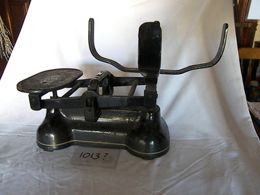
The basic balance scale has been around for thousands of years and its accuracy has improved dramatically over the last several centuries, the principle behind this tool remains unchanged. Its parts include a fulcrum, a beam that balances on it, a pan at the end of the beam to hold the materials to be weighed, and a flat platform at the other for the counter-balancing weights. Balance scales that require equal weights on each side of the fulcrum have been used by everyone from apothecaries and assayers to jewellers and postal workers. Known as an unequal arm balance scale, this variety builds the counterweight into the device. Counter scales used in dry-goods stores and domestic kitchens often featured Japanned or (blackened) cast iron with bronze trims. Made by companies such as Howe and Fairbanks, the footed tin pans of these scales were often oblong, some encircled at one end so bulk items could be easily poured into a bag. Seamless pans were typically stamped from brass and given style names like Snuff (the smallest) and Birmingham (the largest). Some counter scales were designed for measuring spices, others for weighing slices of cake. In the 18th century, spring scales began to appear and would use the resistance of spring to calculate weights, which are read automatically on the scale’s face. The ease of use of spring scales over balance scales. These scales are significant as they identify one of the basic preparation items for the weighing of foodstuff in the family kitchen to prepare everyday meals. This item is significant as it gives a snapshot into domestic life within the average home in Australia around the turn of the twentieth century and is, therefore, an item with social relevance. Black cast iron, medium weighing scales, with a fulcrum which the beam that balances on, there is a scoop or large bowl at one end for the material to be weighted and a flat platform at the other end that holds the weights. Around the cast iron base is an embossed strip weight and bowl missing.flagstaff hill, warrnambool, shipwrecked-coast, flagstaff-hill, flagstaff-hill-maritime-museum, maritime-museum, shipwreck-coast, flagstaff-hill-maritime-village -
 City of Moorabbin Historical Society (Operating the Box Cottage Museum)
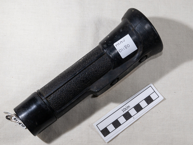
Manufactured Object, Torch 'Eveready' c1950, c1950
George Reed was a draftsman living in the City of Moorabbin c 1950 1899, David Misell, invented this "electric device" ( torch / flashlight) powered by "D" batteries laid front-to-back in a paper tube with the light bulb and a rough brass reflector at the end. Misell assigned his invention over to the American Electrical Novelty and Manufacturing Company owned by Conrad Hubert. In 1905, Hubert changed the name again to The American Ever Ready Company, selling torches / flashlights and batteries under the trademark Ever Ready. In 1906 the British Ever Ready Electrical Company was formed for export of batteries; it became independent in 1914. The American Ever Ready Company became part of National Carbon Company in 1914. The trademark was shortened to Eveready. In 1986, Union Carbide sold its Battery Products Division to Ralston Purina Company becoming the Eveready Battery Company, Inc. and in 1992, it bought the British Ever Ready Electrical Company. Prior to March 1, 1980, the company's alkaline battery had been called the Eveready Alkaline Battery (1959–1968), Eveready Alkaline Energizer (1968–1974) and Eveready Alkaline Power Cell (1974–February 29, 1980). On March 1, 1980, it was rebadged under its current name, Energizer. 2019 production plant in Portage, Wisconsin, but the majority of batteries are made in China and there are also numerous production facilities outside the US. This is an industrial strength Eveready Torch made in England and was used by George Reed, a draftsman, who lived in Bentleigh , City of Moorabbin in mid 20th CLarge 'Eveready' industrial hand torch/ flashlight with rubber protective coverEVEREADY /MADE IN ENGLAND clothing, manufactured lace, dressmaking, blouses, theatrical props, lights, torches, lighting, early settlers, moorabbin shire, mechanics institute cheltenham, postworld war 11 settlers, housing estates moorabbin 1950, bentleigh, ormond, moorabbin, cheltenham, , clark judy, reed gladys, reed george -
 Flagstaff Hill Maritime Museum and Village
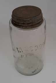
Container - Fruit Preserving Jar, John Landis Mason, 1858-1910
The Masons patent of Nov 30th, 1858 phrase was originally embossed on countless glass fruit jars and canning jars, most ranging in age from circa 1858 to the mid-1910s. John Landis Mason was awarded patent No 22186, issued on November 30, 1858, by the U.S. Patent & Trademark Office it was termed an "Improvement in screw-neck bottles", for his invention concerning the process of creating a threaded screw-type closure on bottles and jars. Similar screw-threading had been done before on some bottles, but the process of forming the upper lip area of the container so that it was smooth, even, and sturdy enough for a lid of standard size to be screwed thereon was difficult and expensive to do properly, often with unsatisfactory results. His improvement revolutionized home canning in the United States and many other countries. In any case, throughout the next 60-odd years, production of jars with the Nov. 30, 1858 embossing continued at a high rate, with untold tens of millions being produced. The phrase was soon considered an important marketing device, adding to the perception of quality and reliability of the container to the average consumer. This perception continued to at least 1879 21 years after the patent was issued, nearly every glass bottle factory was likely producing their version. The 1880s and 1890s likely saw the peak of popularity of these jars. A considerable percentage have a mold number or letter on the base, a means of identifying the particular mold in use at the factory.An early item used in most kitchens by women who preserved fruit and vegetables before the arrival of refrigeration giving a snapshot into the domestic lives of families during the late 19th to early 20th century's and how they preserved food for later use without refrigeration. Preserving jar, glass, with metal screw top lid. Glass has side seams, impurities and slightly concave base. It has been hand blown into a mould. Inscription is moulded into glass. Moulded into glass: MASON'S / PATENT / NOV 30TH / 1838"warrnambool, flagstaff-hill, flagstaff-hill-maritime-museum, maritime-museum, shipwreck-coast, flagstaff-hill-maritime-village, food preserving, mason jar, john landis mason, domestic container, glass jar, fruit & vegetable jar, domestic jar, food preparation, handmade glass, blown glass -
 Flagstaff Hill Maritime Museum and Village
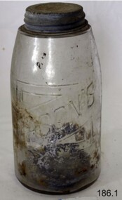
Container - Fruit Preserving Jar, John Landis Mason, 1858-1910
The Masons patent of Nov 30th, 1858 phrase was originally embossed on countless glass fruit jars and canning jars, most ranging in age from circa 1858 to the mid-1910s. John Landis Mason was awarded patent No 22186, issued on November 30, 1858, by the U.S. Patent & Trademark Office it was termed an "Improvement in screw-neck bottles", for his invention concerning the process of creating a threaded screw-type closure on bottles and jars. Similar screw-threading had been done before on some bottles, but the process of forming the upper lip area of the container so that it was smooth, even, and sturdy enough for a lid of standard size to be screwed thereon was difficult and expensive to do properly, often with unsatisfactory results. His improvement revolutionized home canning in the United States and many other countries. In any case, throughout the next 60-odd years, production of jars with the Nov. 30, 1858 embossing continued at a high rate, with untold tens of millions being produced. The phrase was soon considered an important marketing device, adding to the perception of quality and reliability of the container to the average consumer. This perception continued to at least 1879 21 years after the patent was issued, nearly every glass bottle factory was likely producing their version. The 1880s and 1890s likely saw the peak of popularity of these jars. A considerable percentage have a mold number or letter on the base, a means of identifying the particular mold in use at the factory.An early item used in most kitchens by women who preserved fruit and vegetables before the arrival of refrigeration giving a snapshot into the domestic lives of families during the late 19th to early 20th century's and how they preserved food for later use without refrigeration. Preserving glass jar. Glass lip with metal screw top lid. Inscription pressed into glass."Mason's Patent Nov 30th 1858"warrnambool, flagstaff-hill, flagstaff-hill-maritime-museum, maritime-museum, shipwreck-coast, flagstaff-hill-maritime-village, food preserving, mason jar, john landis mason, domestic container, glass jar, fruit & vegetable jar, food storage, preserving jar -
 Puffing Billy Railway
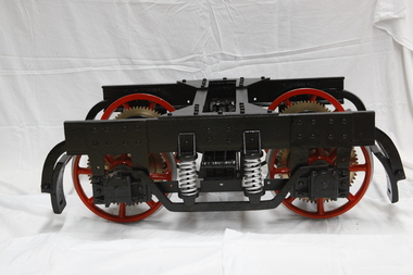
Bogie - Break of Gauge, Circa 1920
Designed and built in the early 1920’s by Charles Robert Prosser , a Melbourne Engineer, for an enquiry by the Commonwealth Government into ways of solving the break of gauge problem. Breaks or changes in railway gauges existed at most state borders of Australia during the first half of the 20th century. Upon completion of this model, it was placed on display in the Federal Parliament then located in Parliament House, Melbourne. Patents on the Break of Gauge Bogie Application number Title Applicant(s) Inventor(s) Filing date 1921000390 Improved means of adjusting the wheels of rolling stock to suit railway tracks of different gauges Charles Robert Prosser Charles Robert Prosser 1921-02-01 1917004843 Improvements in and connected with railway or other ticket supply tubes Charles Robert Prosser Charles Robert Prosser 1917-08-09 1915016191 IMPROVEMENTS IN AND CONNECTED WITH THE ADAPTATION OF RAILWAY ROLLING STOCK TO DIFFERENT GAUGES Charles Robert Prosser Charles Robert Prosser 1915-05-01 1915015980 Improvements in and connected with the adaptation of railway rolling stock to different gauges Charles Robert Prosser Charles Robert Prosser 1915-04-09 1914012931 Improvements in and connected with the adaptation of railway rolling stock to different gauges Charles Robert Prosser Charles Robert Prosser 1914-04-20 The Sydney Morning Herald Fri 2 Sep 1921 Page 6 BREAK OF GAUGE DEVICE. http://nla.gov.au/nla.news-article28088233 Historic - Railway Invention Break of Gauge Bogie Break of Gauge Bogie made of iron and wrought iron & brassboggie, break of gauge, puffing billy -
 Wodonga & District Historical Society Inc
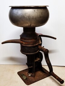
Machine - Cream Separator
A separator is a centrifugal device that separates milk into cream and skimmed milk. Separation was commonly performed on farms in the past. Most farmers milked a few cows, usually by hand, and separated milk with a hand operated machine for domestic use. The milk was poured into the bowl on the top and the handle had to then be turned fast enough to get the separator up to speed adequate to separate the cream and the milk. The milk would come out of one spigot and the cream out of the other. In general practice some of the skimmed milk was consumed by the family, while the rest may have been used to feed calves and pigs. Enough cream was saved to make butter, and the excess was sold. In many cases excess could be bartered or swapped with neighbours for other items of produce. ALFA-LAVAL SEPARATORS The principal works and head office of Aktiebolaget Separator was established by Gustaf de Laval in Stockholm. The first Laval milk separator was patented in1884. In Australia three old established firms commenced pioneering the Alfa Laval cream separators in about 1885. These were A. W. Sandford & Co. Ltd., in Adelaide, J. Bartram & Son, of Melbourne, who have ever since been the Victorian agents of Aktiebolaget Separator. In New South Wales and Queensland, the pioneering firm was Waugh & Josephson Ltd. J. Bartram & Son, the distributor of the separator in this collection, established their business in Melbourne in 1881. In 1892 Bartram & Son estimated that 1,130 of these machines were operating throughout Victoria. This item is significant as it is representative of domestic and dairying machinery used throughout rural areas of Australia in the early to mid 20th century.The separator is made in 3 sections. The base is made from cast iron. The cover and vat are made from silver painted tin. There are 2 outlet spouts. The detachable handle, made from cast iron and wood, is held in place by a screw. A name plate featuring the Victorian distributor, J Bartram & Son of Melbourne and a plate outlining patent information are attached to the base by screws.Around edge of wheel "Aktiebolaget Separator Stockholm/ 2236"dairying industry, dairy machinery, milk separators -
 Flagstaff Hill Maritime Museum and Village
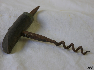
Domestic object - Corkscrew
The design of the corkscrew may have been derived from the gun worm, which was a device from at least the early 1630s, used by men to remove unspent charges from a musket's barrel in a similar fashion. The corkscrew is possibly an English invention, due to the tradition of beer and cider, and the 'Treatise on Cider' by John Worlidge in 1676 describes "binning of tightly corked cider bottles on their sides", although the earliest reference to a corkscrew is, "steel worm used for the drawing of Corks out of Bottles" from 1681. In 1795, the first corkscrew patent was granted to the Reverend Samuel Henshall, in England. The clergyman affixed a simple disc, now known as the Henshall Button, between the worm and the shank. The disc prevents the worm from going too deep into the cork, forces the cork to turn with the turning of the crosspiece, and thus breaks the adhesion between the cork and the neck of the bottle. The disc is designed and manufactured slightly concave on the underside, which compresses the top of the cork and helps keep it from breaking apart. In its traditional form, a corkscrew is simply a steel screw attached to a perpendicular handle, made of wood or some other material. The user grips the handle and screws the metal point into the cork, until the helix is firmly embedded, then a vertical pull on the corkscrew extracts the cork from the bottle. The handle of the corkscrew allows for a commanding grip to ease removal of the cork. https://en.wikipedia.org/wiki/CorkscrewThis object is significant as an example of an item in common use since the late 17th century.Metal corkscrew with wooden handle that is partly broken. Has metal steel spike to create a starting point for the use of the corkscrew. Very rusty. None.flagstaff hill, warrnambool, shipwrecked-coast, flagstaff-hill, flagstaff-hill-maritime-museum, maritime-museum, shipwreck-coast, flagstaff-hill-maritime-village, corkscrew, beverages, kitchen equipment, bottle opener -
 Glenelg Shire Council Cultural Collection
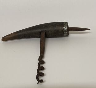
Domestic object - Corkscrew
The design of the corkscrew may have been derived from the gun worm, which was a device from at least the early 1630s, used by men to remove unspent charges from a musket's barrel in a similar fashion. The corkscrew is possibly an English invention, due to the tradition of beer and cider, and the 'Treatise on Cider' by John Worlidge in 1676 describes "binning of tightly corked cider bottles on their sides", although the earliest reference to a corkscrew is, "steel worm used for the drawing of Corks out of Bottles" from 1681. In 1795, the first corkscrew patent was granted to the Reverend Samuel Henshall, in England. The clergyman affixed a simple disc, now known as the Henshall Button, between the worm and the shank. The disc prevents the worm from going too deep into the cork, forces the cork to turn with the turning of the crosspiece, and thus breaks the adhesion between the cork and the neck of the bottle. The disc is designed and manufactured slightly concave on the underside, which compresses the top of the cork and helps keep it from breaking apart. In its traditional form, a corkscrew is simply a steel screw attached to a perpendicular handle, made of wood or some other material. The user grips the handle and screws the metal point into the cork, until the helix is firmly embedded, then a vertical pull on the corkscrew extracts the cork from the bottle. The handle of the corkscrew allows for a commanding grip to ease removal of the cork. https://en.wikipedia.org/wiki/CorkscrewMetal corkscrew with wooden handle. Has metal steel spike to create a starting point for the use of the corkscrew. Very rusty.corkscrew, kitchen equipment, bottle opener -
 Department of Energy, Environment and Climate Action
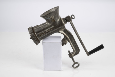
Spong Fuel Mincer
Used to prepare fuel samples to measure their moisture content. Representative samples of fine fuel such as bark, leaves, twigs etc were minced first through a course mincing plate, then a fine plate and the moisture content measured with a Speedy moisture meter or other device. The availability of fuel to burn depends largely on its moisture content. When it exceeds 20-25% not much will burn, whereas 12-15% is generally ideal for fuel reduction burning, but if the moisture content drops as low as 7-10% virtually everything will ignite, and fire behaviour becomes extreme. During the afternoon of the Ash Wednesday bushfires on 16 February 1983 fuel moisture contents were recorded at Stawell as low as 2.7%. Fine fuels like leaves and bark can rapidly absorb moisture after a shower of rain, or from the air when the Relative Humidity (RH) is high, and the temperature is low. Conversely, they can also dry out very quickly. So even though the overall fuel quantity in the forest doesn’t change, the fine fuel availability can increase rapidly from zero after rain to many tonnes per hectare as the fuel dries out. This can happen over a few hours on hot and windy days. Heavy fuels like logs on the ground take longer to dry out. Spong No 10 food mincerforests commission victoria (fcv), bushfire, forest measurement -
 Kiewa Valley Historical Society
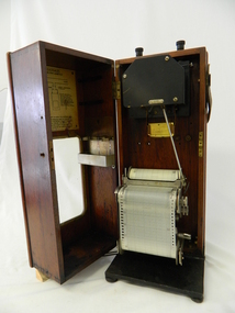
Meter Ammeter Recorder, Circa 1950
This testing voltmeter recorder was last certified by SEC Vic laboratories on the 17/4/77. It was used extensively as mobile recorder placed for periods of one month at locations experiencing unacceptable fluctuations of power. These locations would cover the North East regions of Victoria. They cover voltage drops at domestic and business properties especially those that were experiencing regular fluctuations(daily) at approximately the same time of the day. As the electrical network is required to operate within a set level of voltage, fluctuations outside of this has to be investigated and necessary remedial action taken. This is especially so for rural properties where power "drainage" can occur through animal/bird and tree interference. It can also be the result of defective wiring and overloading at peek operational times (milking machines).This mobile voltage recorder is very significant to the Kiewa Valley because it highlights the difficulties that can occur in maintaining a power supply that experiences fluctuating power demands by the rural industries that it supplies. The requirement of a mobile testing apparatus to cover the various sections in the Kiewa Valley and other rural areas in the northeast region is one of necessity as electricity once connected to a rural property is a labour saving supply as generators on rural properties require a higher degree of maintenance an ultimately at a higher cost. The testing of the SEC Vic supplied electricity to rural properties,those who had previously run on generators, had to be quick and unassuming with certainty of correct supply levels.The mechanism of this voltage recorder has been installed(by the manufacturer) into its own protective wooden box. This box has a front (swing open) lockable section which permits direct access to the installed measuring equipment (for servicing and data collection). The top section of the box has two screw on terminals for access to the machine being tested. This tester has its own inbuilt ink supply facilities and a mechanical clockwork device that unwinds a roll of paper onto a second roll at a rate of 10 mm per hour. The recording chart is marked with time slots against voltage. There is a recording arm which has an ink pen at the end. Both arm and pen carry the ink supply from the ink reservoir, located on the left side of the cabinet door in specially constructed bottle holder( three small bottle capacity). To record a suspect power problem to a home or business establishment the voltmeter is connected to a power supply outlet being tested and wind the recording clockwork mechanism (gives a four week running time). Before leaving the recorder in situ the electrician checks to see if the chart is recording the correct voltage and that the clock mechanism is advancing correctly.On the front of the access "door" at the top a metal label "RECORDING AMMETER" below this "MURDAY SYSTEM" below this "ALTERNATING CURRENT" and below this the manufacturer's registered number "No. 139156" Below this is a metal tag with State Electricity Commission of Victoria Electrical Engineer's Section equipment number "338" Below these tags and above the viewing window is the manufacturer's dtails "EVERSHED & VIGNOLES Led LONDON"sec vic kiewa hydro scheme, alternate energy supplies, alpine feasibility studies temperature, rainfall, power outages -
 The Beechworth Burke Museum
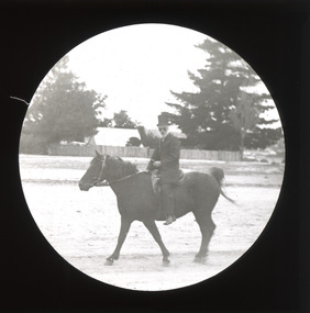
Photograph - Lantern Slide, c1900
This image of a man on horseback is thought to have been taken in Beechworth in approximately 1900. The man pictured may be Chinese. Chinese miners were a significant cultural group in Beechworth's gold rush period. Carole Woods' history of Beechworth, 'A Titan's Field', details a rapid increase in the Chinese population beginning in 1856 that led to Government discrimination and hostility from other miners. Many Chinese people who came to the Victorian goldfields had formerly worked as merchants, mechanics, farmers and shop-keepers. The pictured individual is wearing Western-style clothes indicating prosperity, such as a top hat, so may have held an official position or provided services to the community rather than working as a miner. Lantern slides, sometimes called 'magic lantern' slides, are glass plates on which an image has been secured for the purpose of projection. Glass slides were etched or hand-painted for this purpose from the Eighteenth Century but the process became more popular and accessible to the public with the development of photographic-emulsion slides used with a 'Magic Lantern' device in the mid-Nineteenth Century. Photographic lantern slides comprise a double-negative emulsion layer (forming a positive image) between thin glass plates that are bound together. A number of processes existed to form and bind the emulsion layer to the base plate, including the albumen, wet plate collodion, gelatine dry plate and Woodburytype techniques. Lantern slides and magic lantern technologies are seen as foundational precursors to the development of modern photography and film-making techniques.This glass slide is significant because it provides insight into Beechworth's cultural and social relationships in the early Twentieth Century, in particular the experiences of Chinese people. It is also an example of an early photographic and film-making technology in use in regional Victoria in the time period.Thin translucent sheet of glass with a circular image printed on the front and framed in a black backing. It is held together by metals strips to secure the edges of the slide.burke museum, beechworth, lantern slide, slide, glass slide, plate, burke museum collection, photograph, monochrome, magic lantern, indigo shire, north-east victoria, nineteenth century, 1900s, twentieth century, emulsion slides, chinese, chinese miners, immigration, racism, classism, social groups, cultural groups, horse riding, horses, equestrian, horseback -
 City of Moorabbin Historical Society (Operating the Box Cottage Museum)
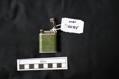
Manufactured objects, Cigarette lighter metal, 20thC
A cigarette lighter is a portable device used to generate a flame. It consists of a metal or plastic container filled with a flammable fluid or pressurized liquid gas, a means of ignition, and some provision for extinguishing the flame. A spark is created by striking metal against a flint, or by pressing a button that compresses a piezoelectric crystal (piezo ignition), generating an electric arc. In naphtha lighters, the liquid is sufficiently volatile, and flammable vapour is present as soon as the top of the lighter is opened. Butane lighters combine the striking action with the opening of the valve to release gas. The spark ignites the flammable gas causing a flame to come out of the lighter which continues until the top is closed (naphtha type), The Beney Company was founded by Robert Ernest Beney of London, England. R. E. Beney invented and marketed the first Beney mechanical lighter in 1919. Beney also designed and manufactured numerous luxury lighters and striker boxes for Alfred Dunhill of London as well as Hermes of Paris. In 1938, Beckenham based Beney Lighters was acquired, adding utility lighters and precision tools to the company's (Winn & Coates) ever growing list of products. The biggest selling line manufactured by Beney was the Economic Gas Lighter which hung on the side of housewife's gas cookers and was also used for lighting Bunsen burners in laboratories. In 1939-1940 the company moved its administration to the Beney Lighter premises in Beckenham after the Head Office at Trinity Square along with many company records were destroyed in a 'doodlebug' flying bomb attack. Beney Ltd. continued producing lighters at least through the late 1954. A green metal cigarette lighter that used fuel and a striking action arm to produce a flame .base: BENEY / COMPANION / PATENT 568897 / BRITISH MADEtobacco, cigarettes, cigarette lighters, fuels, moorabbin, cheltenham, bentleigh, early settlers, beney pty ltd, beckenham england -
 Flagstaff Hill Maritime Museum and Village
Functional object - Kerosene Lamp, Perko Inc, 1922 -1930
The company was originally founded by Frederick Perkins a Russian immigrant schooled in Germany as a machinist and tool and die, maker. Frederick came to the United States in the early 1890s and soon became employed as a machinist for E.W. Bliss & Company in Brooklyn, New York. In the early 1900s, he and a partner began operating a business, F. Persky & Company, Lantern Manufacturer, out of the basement of his house. In 1907, Frederick's son Louis joined him in the business, and together they enlarged both the product line and the manufacturing facilities. By 1912, they had seventeen employees and made a wide range of marine lanterns and products. The business continued operating until 1913 when Frederick became president of National Marine Lamp Company, based out of Forestville, Connecticut. Frederick and Louis left that company in 1916 and moved back to Brooklyn, New York, where they started Perkins Marine Lamp Corporation. Five generations later, PERKO is still a privately owned, family-operated corporation. Perkins Marine Corporation was initially known as Perkins Marine Lamp, Inc. The original focus was on the manufacture of hand-formed sheet metal products for the marine market. The first “Perko” catalogue was published in 1916. It included a full range of kerosene and electric lanterns for small and large boats, ventilators, chart cases, signalling devices, mooring buoys, pumps and a variety of spare parts. These products, fabricated from brass, copper and galvanized sheet metal, began a reputation for producing high-quality products. In 1922, the "PERKO" trademark was instituted with each new product utilising the latest, sophisticated metal manufacturing technology.A significant item from an American manufacturer that specialises in making marine products and is still in business today under the same trade name. The subject item is significant as it was made not long after the trade name of PERKO was registered in 1922 and began to be used on the company's various products.Kerosene lamp with circular fuel tank and chrome plated reflector shield. "PERKO" stamped on base.warrnambool, flagstaff-hill, flagstaff-hill-maritime-museum, maritime-museum, shipwreck-coast, flagstaff-hill-maritime-village, kerosene lamp, marine lamp, perko inc, lighting, marine accessories manufacturer -
 Australian Gliding Museum
Machine - Winch - for auto tow launching cable laying and retrieval
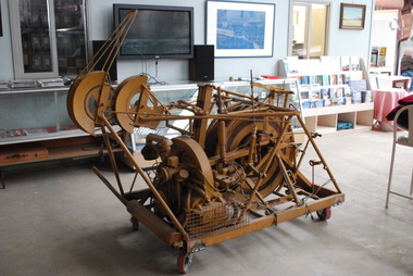
The auto tow launching mechanism was designed by Ray Jamieson of Cobram in the north of Victoria. The prototype was built the for the Corowa Gliding Club where it was used for some years. After Ray’s brother, Bert Jamieson, had witnessed the machine in use at Corowa, at Bert’s request, Ray built second one (the Museum’s exhibit) for use at Bacchus Marsh airfield. Bert lived in Melbourne at the time and was a member of the Victorian Motorless Flight Group (VMFG) which used Bacchus Marsh airfield. This occurred in the 1970s. The method of operation was to have the auto tow mechanism mounted in the back of a utility motor vehicle. The launching cable was attached to the glider. With the Volkswagen engine of the mechanism running, the tow vehicle would then drive along the runway to commence the launch. The mechanism would automatically apply brake pressure to the cable drum as the vehicle proceeded freely letting out the cable and then smoothly towing the glider into the air. When the launching cable reached a certain angle, the pilot would release the cable from the glider at which point the winching mechanism would automatically retrieve the cable in preparation for the next launch. This allowed quicker restarts and the flexibility of easily changing runways to suit the wind conditions. It made gliding a simple and cost-effective operation. Ray Jamieson and his son often used the prototype which they named “George” at Corowa in this way. With the exception of several demonstration launches, the Museum’s example of this type of device was not used by the VMFG at Bacchus Marsh due to rulings by the Department of Civil Aviation encouraging the use of aero tow launching at their site. As far as is known this is the only device of its type in the world and is indicative of the ingenuity found amongst the Australian gliding fraternity.Single drum and motorized drive mechanism mounted on a mobile steel frame.australian gliding, glider, sailplane, auto towing, launching, jamieson, corowa gliding club, victorian motorless flight group, vmfg