Showing 331 items matching "electrical equipment"
-
 Melbourne Tram Museum
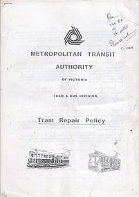
Document - Report, Metropolitan Transit Authority (MTA), "Metropolitan Transit Authority of Victoria - Tram and Bus Division - Tram Repair Policy", c1988
... . Includes notes on Bogies, bodywork and fitting, electrical.... Includes notes on Bogies, bodywork and fitting, electrical ...Document - policy - report - 28 A4 pages, stapled in the top left hand corner titled, "Metropolitan Transit Authority of Victoria - Tram and Bus Division - Tram Repair Policy". Has table of contents. Looks at the identification of tasks between the tram construction and maintenance branch of the Tram Servicing branch. Includes notes on Bogies, bodywork and fitting, electrical and electronic equipment, W class air equipment and W class mechanical braking equipment.Has a list on the top right hand corner for distribution and "c1988" in ink.trams, tramways, mta, w class, maintenance, construction -
 Kiewa Valley Historical Society
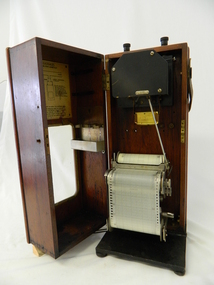
Meter Ammeter Recorder, Circa 1950
... Electricity Commission of Victoria Electrical Engineer's Section... with State Electricity Commission of Victoria Electrical Engineer's ...This testing voltmeter recorder was last certified by SEC Vic laboratories on the 17/4/77. It was used extensively as mobile recorder placed for periods of one month at locations experiencing unacceptable fluctuations of power. These locations would cover the North East regions of Victoria. They cover voltage drops at domestic and business properties especially those that were experiencing regular fluctuations(daily) at approximately the same time of the day. As the electrical network is required to operate within a set level of voltage, fluctuations outside of this has to be investigated and necessary remedial action taken. This is especially so for rural properties where power "drainage" can occur through animal/bird and tree interference. It can also be the result of defective wiring and overloading at peek operational times (milking machines).This mobile voltage recorder is very significant to the Kiewa Valley because it highlights the difficulties that can occur in maintaining a power supply that experiences fluctuating power demands by the rural industries that it supplies. The requirement of a mobile testing apparatus to cover the various sections in the Kiewa Valley and other rural areas in the northeast region is one of necessity as electricity once connected to a rural property is a labour saving supply as generators on rural properties require a higher degree of maintenance an ultimately at a higher cost. The testing of the SEC Vic supplied electricity to rural properties,those who had previously run on generators, had to be quick and unassuming with certainty of correct supply levels.The mechanism of this voltage recorder has been installed(by the manufacturer) into its own protective wooden box. This box has a front (swing open) lockable section which permits direct access to the installed measuring equipment (for servicing and data collection). The top section of the box has two screw on terminals for access to the machine being tested. This tester has its own inbuilt ink supply facilities and a mechanical clockwork device that unwinds a roll of paper onto a second roll at a rate of 10 mm per hour. The recording chart is marked with time slots against voltage. There is a recording arm which has an ink pen at the end. Both arm and pen carry the ink supply from the ink reservoir, located on the left side of the cabinet door in specially constructed bottle holder( three small bottle capacity). To record a suspect power problem to a home or business establishment the voltmeter is connected to a power supply outlet being tested and wind the recording clockwork mechanism (gives a four week running time). Before leaving the recorder in situ the electrician checks to see if the chart is recording the correct voltage and that the clock mechanism is advancing correctly.On the front of the access "door" at the top a metal label "RECORDING AMMETER" below this "MURDAY SYSTEM" below this "ALTERNATING CURRENT" and below this the manufacturer's registered number "No. 139156" Below this is a metal tag with State Electricity Commission of Victoria Electrical Engineer's Section equipment number "338" Below these tags and above the viewing window is the manufacturer's dtails "EVERSHED & VIGNOLES Led LONDON"sec vic kiewa hydro scheme, alternate energy supplies, alpine feasibility studies temperature, rainfall, power outages -
 Eltham District Historical Society Inc
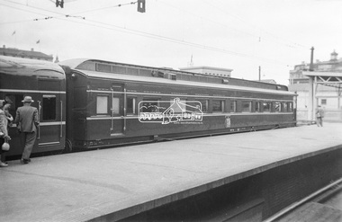
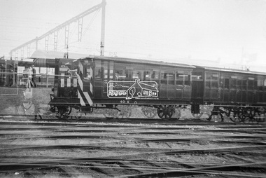
Photograph, George Coop, The Royal Train, on display at Spencer Street Railway Station during the 1954 Victorian Railways Centenary Exhibition, Sep. 1954
... of rolling stock, track, electrical and other railway equipment held... of rolling stock, track, electrical and other railway equipment held ..."V.R. Cavalcade" Centenary 1854-1954 Exhibition (11-25 Sep 1954) presented a model railway occupying about 1,400 square feet in the Lower Town Hall featuring a number of model railway working scale models. The exhibition also included a display of rolling stock, track, electrical and other railway equipment held at Spencer Street Railway Station.Digital TIFF file Scan of Kopdak 620 black and white negative transparencygeorge coop collection, royal train, display, spencer street railway station, v.r. cavalcade, victorian railways centenary 1854-1954 exhibition -
 Eltham District Historical Society Inc
Photograph, George Coop, The Royal Train, on display at Spencer Street Railway Station during the 1954 Victorian Railways Centenary Exhibition, Sep. 1954
... of rolling stock, track, electrical and other railway equipment held... of rolling stock, track, electrical and other railway equipment held ..."V.R. Cavalcade" Centenary 1854-1954 Exhibition (11-25 Sep 1954) presented a model railway occupying about 1,400 square feet in the Lower Town Hall featuring a number of model railway working scale models. The exhibition also included a display of rolling stock, track, electrical and other railway equipment held at Spencer Street Railway Station.Digital TIFF file Scan of Kopdak 620 black and white negative transparencygeorge coop collection, royal train, display, spencer street railway station, v.r. cavalcade, victorian railways centenary 1854-1954 exhibition -
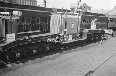 Eltham District Historical Society Inc
Photograph, George Coop, Power transformer on a QB boiler/flat wagon on display at Spencer Street Railway Station during the 1954 Victorian Railways Centenary Exhibition, Sep. 1954
... of rolling stock, track, electrical and other railway equipment held... of rolling stock, track, electrical and other railway equipment held ..."V.R. Cavalcade" Centenary 1854-1954 Exhibition (11-25 Sep 1954) presented a model railway occupying about 1,400 square feet in the Lower Town Hall featuring a number of model railway working scale models. The exhibition also included a display of rolling stock, track, electrical and other railway equipment held at Spencer Street Railway Station.Digital TIFF file Scan of Kopdak 620 black and white negative transparencygeorge coop collection, display, spencer street railway station, v.r. cavalcade, victorian railways centenary 1854-1954 exhibition, power transformer, qb boiler/flat wagon, qb-13 -
 Eltham District Historical Society Inc
Photograph, George Coop, Steam locomotive E-class 2-4-2 on display at Spencer Street Railway Station during the 1954 Victorian Railways Centenary Exhibition, Sep. 1954
... of rolling stock, track, electrical and other railway equipment held... of rolling stock, track, electrical and other railway equipment held ..."V.R. Cavalcade" Centenary 1854-1954 Exhibition (11-25 Sep 1954) presented a model railway occupying about 1,400 square feet in the Lower Town Hall featuring a number of model railway working scale models. The exhibition also included a display of rolling stock, track, electrical and other railway equipment held at Spencer Street Railway Station.Digital TIFF file Scan of Kopdak 620 black and white negative transparencygeorge coop collection, display, spencer street railway station, v.r. cavalcade, victorian railways centenary 1854-1954 exhibition, e-class steam locomotive -
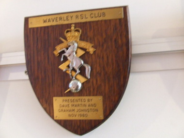 Waverley RSL Sub Branch
Plaque Royal Australian Electrical and Mechanical Engineers, Royal Australian Electrical and Mechanical Engineers
... of all land electrical and mechanical equipment. RAEME has... of all land electrical and mechanical equipment. RAEME has ...The Royal Corps of Australian Electrical and Mechanical Engineers (RAEME; pronounced Raymee) is a corps of the Australian Army that has responsibility for the maintenance and recovery of all land electrical and mechanical equipment. RAEME has members from both the Australian Regular Army and The Army Reserve. Prior to being given the title of 'Royal', the Australian Electrical and Mechanical Engineers (AEME) were raised on 1 December 1942. Some 64 years later, on 1 December 2006, the last independent RAEME Workshop was disbanded. RAEME soldiers continue in their role to provide support through attachment to other units in Tech Support Troops, Sections or Platoons.Wooden Plaque 15cm x 13cm with insignia of Royal Australian Electrical and Mechanical Engineers Royal Australian Electrical and Mechanical Engineers -
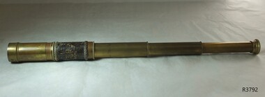 Flagstaff Hill Maritime Museum and Village
Instrument - Three draw Telescope, 20th century
... , photometers, cameras, ophthalmoscopes, and electrical equipment..., and electrical equipment such as electric lamps. Liverpool was a major ...This telescope was amongst various items collected from a sea dive in Port Phillip Bay. The diver was the caretaker of the Port Lonsdale Lighthouse, who dived on various wrecks in the bay during the 1960's. After the caretaker's death, his son sold off many of the shipwreck artefacts. The telescope was purchased from the caretaker's son in the 1990's by a previous owner of the Marine Shop, Queenscliff, Victoria. Many companies were making scientific instruments in Liverpool. Between 1730 up too today, they manufactured spectroscopes, telescopes, microscopes, barometers, photometers, cameras, ophthalmoscopes, and electrical equipment such as electric lamps. Liverpool was a major centre for the production of scientific items rivaling Glasgow and London from 1850 to 1920. This telescope appears to be of quality manufacture but the origins can only be surmised at based on the gold embossing to the leather surrounding the main brass tube as being associated with Liverpool England. There is no maker or owners mark, so again there is no sure way to determine the year of manufacture or maker. There were many opticians and scientific instrument makers working in and around Liverpool from 1730 through too today. Also the possibility the telescope could have been made outside Liverpool overseas should not be overlooked and may have been made as a souvenir item from Liverpool from the mid to late 20th century. The size and type of telescope is a traditional type that was used for many sporting activities in the mid to late 19th century for deer stalking, bird watching, or used generally. I believe the item dates from sometime around the early to late part of the 20th century as the use of the liver bird mark became popular in 1911. It began appearing on many manufactured items of the period up too today, denoting that these items were made by companies operating in or around Liverpool England. If the item had been made by a notable firm it would have been engraved with the makers name city of origin, or owner as was the accepted practice for these items. The writer has been unable to determine if any specific company had had exclusive use of the liver bird logo as it was widely used and was not copyrighted until the Liverpool football club successfully won a court case giving them the sole rights to the trademark in 2012.The item is also an example of the shipwreck artefacts gathered along the southwest coast of Victoria. It is also a sample of scientific instruments used up to the mid 20th century.Victorian style gentleman's three draw brass telescope with machine milling surrounding the end of each tube and around the objective end. The three tube draw has no split and all three cartridges are held within the main brass tube wrapped in leather with rope bindings at both ends 5 cm in length and beginning 7 cm from the objective end. The last 2.8 cm makes up the remainder of the brass tube which has a sliding brass sunshade. The eyepiece is flat and has a protective slide over the lens aperture. Two relay lenses are missing on the ends of the second and third tube. Gold embossed into the leather an inscription “Trade the Liver Mark” also embossed in gold a depiction of the mythical liver bird, associated with the city seal of Liverpool England. flagstaff hill, flagstaff hill maritime museum and village, warrnambool, maritime museum, maritime village, great ocean road, shipwreck coast, shipwreck artefact, port phillip bay, port lonsdale lighthouse, wreck, 1960’s diver, queenscliff marine shop, liver bird, scientific instrument, telescope, three drawer telescope, liverpool, liver bird trade mark, trade mark -
 Eltham District Historical Society Inc
Photograph, George Coop, Steam locomotive E-class 2-4-2 on display at Spencer Street Railway Station during the 1954 Victorian Railways Centenary Exhibition, Sep. 1954
... a display of rolling stock, track, electrical and other railway... a display of rolling stock, track, electrical and other railway ...Located at the end of the train is the E-class electric locomotive 1101 "V.R. Cavalcade" Centenary 1854-1954 Exhibition (11-25 Sep 1954) presented a model railway occupying about 1,400 square feet in the Lower Town Hall featuring a number of model railway working scale models. The exhibition also included a display of rolling stock, track, electrical and other railway equipment held at Spencer Street Railway Station.Digital TIFF file Scan of Kopdak 620 black and white negative transparencygeorge coop collection, display, spencer street railway station, v.r. cavalcade, victorian railways centenary 1854-1954 exhibition, e-1101, e-class electric locomotive, e-class steam locomotive -
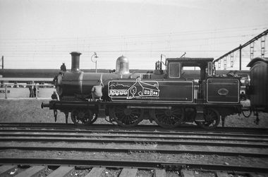
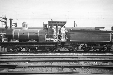 Eltham District Historical Society Inc
Photograph, George Coop, Steam locomotive T-94 on display at Spencer Street Railway Station during the 1954 Victorian Railways Centenary Exhibition, Sep. 1954
... stock, track, electrical and other railway equipment held... stock, track, electrical and other railway equipment held ...Steam locomotive T-94 has been preserved and is currently on display at the Australian Railway Historical Society Museum at North Williamstown http://www.australiansteam.com/T%2094.htm "V.R. Cavalcade" Centenary 1854-1954 Exhibition (11-25 Sep 1954) presented a model railway occupying about 1,400 square feet in the Lower Town Hall featuring a number of model railway working scale models. The exhibition also included a display of rolling stock, track, electrical and other railway equipment held at Spencer Street Railway Station.Digital TIFF file Scan of Kopdak 620 black and white negative transparencygeorge coop collection, display, spencer street railway station, v.r. cavalcade, victorian railways centenary 1854-1954 exhibition, t-94, t-class steam locomotive -
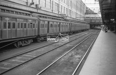 Eltham District Historical Society Inc
Photograph, George Coop, View of Tait Red Rattler at No. 1 Platform, Flinders Street Railway Station, Sep. 1954
... stock, track, electrical and other railway equipment held... stock, track, electrical and other railway equipment held ...Most likjely taken either arriving or departing from a visit of the display at Spencer Street Railway Station during the 1954 Victorian Railways Centenary Exhibition, 11-25 Sep. 1954 "V.R. Cavalcade" Centenary 1854-1954 Exhibition (11-25 Sep 1954) presented a model railway occupying about 1,400 square feet in the Lower Town Hall featuring a number of model railway working scale models. The exhibition also included a display of rolling stock, track, electrical and other railway equipment held at Spencer Street Railway Station.Digital TIFF file Scan of Kopdak 620 black and white negative transparencygeorge coop collection, v.r. cavalcade, victorian railways centenary 1854-1954 exhibition, red rattler, tait train -
 Melbourne Tram Museum
Document - Specification, Melbourne & Metropolitan Tramways Board (MMTB), "Design, Manufacture and delivery of 100 only all-electric trams", Jun. 1965
... , electrical equipment, control panels and drawings. The drawings give..., wheels, brakes, electrical equipment, control panels and drawings ...Specification or Tender Document - titled "Design, Manufacture and delivery of 100 only all-electric trams", and "Background Information and Preliminary Specification", dated June 1965. Bound into a brown foolscap card cover. Details the conditions of tender, conditions of contract, notes, specification, gives background information about Melbourne, dimensions, performance, drivers and conductors, trucks, wheels, brakes, electrical equipment, control panels and drawings. The drawings give a map of the system, typical city route, Glenferrie Road route (grade diagram), concrete track construction, min. radius curves, loading gauge, all-electric tram and mounting details for the trolley base, schedule of prices, tender form, form of contract, schedule of information to be provided by the tenderer. Comprises: 1 - Conditions of Tendering - 1 page 2 - Conditions of Contract - 4 pages 3 - Contents - 3 pages 4 - Notes for prospective tenderers - dated June 1965 5 - General nature of contract - 21 pages 6 - Appendix A - climate data - two sheets 7 - List of 14 appended drawings 8 - O.6887A - cross section of trolley wire 9 - P.13855 - Glenferrie Road, Longitudinal Section 10 - P.13856 - Wattle Park Route 11 - P.13857 - East Preston Route 12 - P13858 - Concrete track construction 13 - P13859 - Open track construction 14 - P.13860 - Paved ballast track construction 15 - P.13887 - Tram Route - locations of substations and section switches 16 - P.13888 - Minimum radius service curves to give minimum clearance between tramcars 17 - P.13889 - Grooved Rail - 102 pounds per yard and tire profile 18 - R10-301 - Loading gauge, proposed electric tramcars 19 - R9706K - Rolling stock data, tramcars 20 - R10306 - Collins Points Shifter - Wiring diagram. 21 - Schedule of data to be supplied by the tenderer 22 - notes on Automatic Points shifters - 2 sheets 23 - Tender prices and delivery periods - 2 sheets. See Reg Item 2266 for the 1972 version and 1583 for the August 1966 version. See Reg Item 4049 for associated newspaper cuttings. See file htd4667i1.pdf for scans of the drawings.In ink in top right hand corner - "Lees"trams, tramways, specification, tenders, z class, mmtb, melbourne -
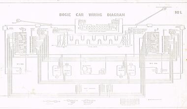 Melbourne Tram Museum
Drawing, Victorian Railways, Bogie Car wiring diagram, c1950's
... Set of four drawings of electrical and brake equipment... drawings of electrical and brake equipment on VR Tramcars. .1 ...Set of four drawings of electrical and brake equipment on VR Tramcars. .1 - No. 1 - Bogie car wiring diagram - shows all equipment including lights, compressors, motors and switches. Has a different lighting circuit for the 52 to 54. 4 copies held. .2 - No. 2 - Air and Brake Equipment (Excluding one-man car) - shows all equipment including wipers, conductor's brake valve .3 - No. 3 - Pneumatic Equipment for One-man car - shows all equipment including door engines, emergency valves, emergency reservoirs, door valves and links to controller. .4 - No. 4 - Pneumatic Door Equipment - cars 52 to 54 - including door controller valve positions.trams, tramways, vr class tramcars, victorian railways, brakes, wiring diagrams, one man trams, air compressors -
 Eltham District Historical Society Inc
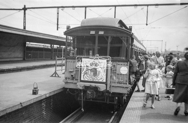
Photograph, George Coop, The Royal Train, on display at Spencer Street Railway Station during the 1954 Victorian Railways Centenary Exhibition, Sep. 1954
... a display of rolling stock, track, electrical and other railway... included a display of rolling stock, track, electrical and other ...It appears that the Royal Train may have been split to suit display purposes and restraints. In this image is seen the CE Guard's Brake Van which would be located as the first coach behind the locomotive. "V.R. Cavalcade" Centenary 1854-1954 Exhibition (11-25 Sep 1954) presented a model railway occupying about 1,400 square feet in the Lower Town Hall featuring a number of model railway working scale models. The exhibition also included a display of rolling stock, track, electrical and other railway equipment held at Spencer Street Railway Station.Digital TIFF file Scan of Kopdak 620 black and white negative transparencygeorge coop collection, royal train, display, spencer street railway station, v.r. cavalcade, victorian railways centenary 1854-1954 exhibition, ce guard's brake van -
 Flagstaff Hill Maritime Museum and Village
Instrument - Marine Telescope, 1870-1880
... , ophthalmologist, and electrical equipment such as electric lamps. John..., ophthalmologist, and electrical equipment such as electric lamps. John ...This telescope was amongst various items collected from a sea dive in Port Phillip Bay. The diver was the caretaker of the Port Lonsdale Lighthouse, who dived on various wrecks in the bay during the 1960's. After the caretaker's death, his son sold off many of the shipwreck artefacts. The telescope was purchased from the caretaker's son in the 1990's by a previous owner of the Marine Shop, Queenscliff, Victoria. John Browning was particularly well known for his scientific advances in the fields of spectroscopy, astronomy, and optometry. Between 1856 and 1872, Browning acquired provisional patents for designs of numerous scientific instruments. He was also the recipient of an award at the 1862 International Exhibition held in London. Also recognised for his temperature-compensated aneroid barometer. Browning's scientific instruments were used in physics, chemistry, and biology. The products he designed and manufactured included spectroscopes, telescopes, microscopes, barometers, photometers, cameras, ophthalmologist, and electrical equipment such as electric lamps. John Browning was born around 1831 in Kent, England. His father, William Spencer Browning, was a maker of nautical instruments. John Browning's great-grandfather was also an instrument maker as well as John’s brother Samuel Browning of the firms Spencer & Browning and Spencer, Browning & Rust, who also manufactured navigational instruments. The latter firm was in operation in London from 1784 to 1840 and was succeeded by the firm of Spencer, Browning & Co. John Browning initially intended to follow the medical profession and entered Guy's Hospital, a teaching hospital and a school of medicine. Despite having passed the required examinations, however, he abandoned his plans. Instead, he apprenticed with his father, William Spencer Browning. At the same time, in the late 1840s, he was a student attending the Royal College of Chemistry several days per week. By the early 1870s, practical optics had become John Browning's primary interest, and he listed his occupation as an optician on the census records from 1871 to 1901. He was well known among London's ophthalmic surgeons for his various ophthalmic instruments. He had a large part in reforming the art of crafting spectacles. Other achievements were as an author of the book, How to Use Our Eyes and How to Preserve them by the Aid of Spectacles. Published in 1883, the book included thirty-seven illustrations, including a diagram demonstrating the anatomy of the eye. In 1895, he was one of the founders of the "British Ophthalmology" the first professional organisation for optometry. He was not only its first president but also registered as its first member so many considered him to be the first professional optometrist. Other professional organisations he belonged too was as a member of “The Aeronautical Society of Great Britain”. In 1871 constructing the first wind tunnel located at Greenwich Marine Engineering Works. He was also a member of other scientific organisations, such as the “Microscopical Society of London”, the “Meteorological Society”, and the “Royal”. Then in 1908 the company of W. Watson & Son, opticians and camera makers, took over John Browning's company since 1901 John Browning had been semi-retired but in 1908 he fully retired and moved to Bournemouth in Hampshire. He died in Cheltenham, Gloucestershire in 1925.The telescope is significant for its association with one of the world’s leading scientific instrument makers and inventor of the 19th and early 20th century. It is believed the donation came off a wreck either in Port Philip Bay or between Point Lonsdale and the Nepean Heads making it a significant maritime historical artefact. Its provenance is good given it was taken off a wreck in this area by the Point Lonsdale lighthouse caretaker. Examples of John Browning's telescopes because of their scientific and historical importance are highly valued by collectors.Marine style single draw brass telescope with a sunshade. The single draw has no split and the second cartridge is held in a long brass tube within the single draw, mounted from the objective end. The eyepiece is flat and at the end of the first draw in a very faded engraving that is believed to read "John Browning, 63 Strand, and should read London under the word strand but this is hard to establish given the engravings condition. This interpretation of the engraving has been arrived at by examination of other John Browning telescope engraving examples."John Browning, engraved to the first tube in copper plate style "63 STRAND" Engraved under in capital textflagstaff hill, flagstaff hill maritime museum and village, warrnambool, maritime museum, maritime village, great ocean road, shipwreck coast, shipwreck artefact, port phillip bay, port lonsdale lighthouse, wreck, 1960’s diver, queenscliff marine shop, john browning, telescope, spectroscopy, optometry, scientific instruments, william spencer browning, optician, navigational instrument, microscopical society of london, aeronautical society, marine technology -
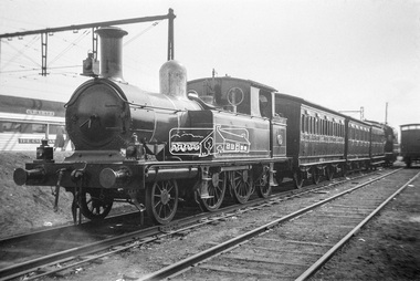
 Eltham District Historical Society Inc
Photograph, George Coop, E-class electric locomotive E-1101 on display at Spencer Street Railway Station during the 1954 Victorian Railways Centenary Exhibition, Sep. 1954
... , track, electrical and other railway equipment held at Spencer..., track, electrical and other railway equipment held at Spencer ...The white disc at the front of the train is folded in half covering trhe white circle indicating this is the front of the train. When the full white disc is visible, this signifies the end of the train. See similar image taken just moments prior - https://www.victorianrailways.net/motive%20power/e/e.html "V.R. Cavalcade" Centenary 1854-1954 Exhibition (11-25 Sep 1954) presented a model railway occupying about 1,400 square feet in the Lower Town Hall featuring a number of model railway working scale models. The exhibition also included a display of rolling stock, track, electrical and other railway equipment held at Spencer Street Railway Station.Digital TIFF file Scan of Kopdak 620 black and white negative transparencygeorge coop collection, display, spencer street railway station, v.r. cavalcade, victorian railways centenary 1854-1954 exhibition, e-1101, e-class electric locomotive -
 Eltham District Historical Society Inc
Photograph, George Coop, Steam locomotive T-94 on display at Spencer Street Railway Station during the 1954 Victorian Railways Centenary Exhibition, Sep. 1954
... a display of rolling stock, track, electrical and other railway... a display of rolling stock, track, electrical and other railway ...Visible behind T-94 is an AEC Railmotor (with tiger stripes on front) and trailer used on branch lines to haul a 4-wheel trailer. Steam locomotive T-94 has been preserved and is currently on display at the Australian Railway Historical Society Museum at North Williamstown http://www.australiansteam.com/T%2094.htm "V.R. Cavalcade" Centenary 1854-1954 Exhibition (11-25 Sep 1954) presented a model railway occupying about 1,400 square feet in the Lower Town Hall featuring a number of model railway working scale models. The exhibition also included a display of rolling stock, track, electrical and other railway equipment held at Spencer Street Railway Station.Digital TIFF file Scan of Kopdak 620 black and white negative transparencygeorge coop collection, display, spencer street railway station, v.r. cavalcade, victorian railways centenary 1854-1954 exhibition, aec railmotor, railmotor, t-94, t-class steam locomotive -
 Eltham District Historical Society Inc
Photograph, George Coop, Double exposure: AEC Railmotor and Trailer on display at Spencer Street Railway Station during the 1954 Victorian Railways Centenary Exhibition, Sep. 1954
... , electrical and other railway equipment held at Spencer Street Railway..., electrical and other railway equipment held at Spencer Street Railway ...Double or exposure containing an AEC Railmotor (with tiger stripes on front) and 4-wheel trailer used on branch lines. Where the strips appear to curve down is a sun visor over the windscreen of the railmotor. The image is double exposed with a E-class 2-4-2 steam locomotive and Tait train on display adjacent "V.R. Cavalcade" Centenary 1854-1954 Exhibition (11-25 Sep 1954) presented a model railway occupying about 1,400 square feet in the Lower Town Hall featuring a number of model railway working scale models. The exhibition also included a display of rolling stock, track, electrical and other railway equipment held at Spencer Street Railway Station.Digital TIFF file Scan of Kopdak 620 black and white negative transparencygeorge coop collection, display, spencer street railway station, v.r. cavalcade, victorian railways centenary 1854-1954 exhibition, aec railmotor -
 Bendigo Historical Society Inc.
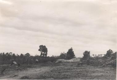
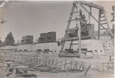
Photograph - Napoleon Reef Gold Mine Battery Site, 1936
... lavish of Bendigo's mines. Plant and equipment were electrically... lavish of Bendigo's mines. Plant and equipment were electrically ...The Napoleon (BML) gold mine (1932) was located beside McDougall Road, Golden Gully, between Martin and Hattam Street. It had a depth of 921 feet. It was one of the latest and most lavish of Bendigo's mines. Plant and equipment were electrically driven. The four-compartment shaft, extra large by goldfield's standards, measured 17 feet 6 inches by 5 feet 2 inches and was cement lined below 900 feet instead of being red gum boxed as was the usual practice. The workshop was equipped to carry out all repairs for the equally lavish BML mines on the Nell Gwynne and Carshalton reefs. (The Gold Mines of Bendigo, Book 2, Arthur Victor Palmer)Significant to mining history of Bendigo.Black and white photograph. Image shows flat, open landscape with four large eucalypt trees in centre of image. Four men working with shovels on left hand side of image, one man with wheelbarrow and dog alongside. Wooden framed structure on right hand side. Written in pencil on back of photograph: ' Battery excavations started 22/9/36' and 'excavations started'.napoleon gold mine, napoleon reef gold mine -
 Bendigo Historical Society Inc.
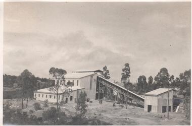
Photograph - Napoleon Mine Battery, 1936
... lavish of Bendigo's mines. Plant and equipment were electrically... lavish of Bendigo's mines. Plant and equipment were electrically ...The Napoleon (BML) gold mine (1932) was located beside McDougall Road, Golden Gully, between Martin and Hattam Street. It had a depth of 921 feet. It was one of the latest and most lavish of Bendigo's mines. Plant and equipment were electrically driven. The four-compartment shaft, extra large by goldfield's standards, measured 17 feet 6 inches by 5 feet 2 inches and was cement lined below 900 feet instead of being red gum boxed as was the usual practice. The workshop was equipped to carry out all repairs for the equally lavish BML mines on the Nell Gwynne and Carshalton reefs. (The Gold Mines of Bendigo, Book 2, Arthur Victor Palmer)Significant to mining history of Bendigo.Black and white photograph: landscape view of mine sheds. Battery shed fully completed with trestleway to another shed. Trees in background. Written in pencil on back of photograph: 'completed battery 5/12/36'napoleon gold mine, napoleon reef gold mine -
 Bendigo Historical Society Inc.
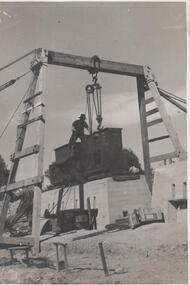
Photograph - Napoleon Reef Gold Mine Battery Site, 1936
... lavish of Bendigo's mines. Plant and equipment were electrically... lavish of Bendigo's mines. Plant and equipment were electrically ...The Napoleon (BML) gold mine (1932) was located beside McDougall Road, Golden Gully, between Martin and Hattam Street. It had a depth of 921 feet. It was one of the latest and most lavish of Bendigo's mines. Plant and equipment were electrically driven. The four-compartment shaft, extra large by goldfield's standards, measured 17 feet 6 inches by 5 feet 2 inches and was cement lined below 900 feet instead of being red gum boxed as was the usual practice. The workshop was equipped to carry out all repairs for the equally lavish BML mines on the Nell Gwynne and Carshalton reefs. (The Gold Mines of Bendigo, Book 2, Arthur Victor Palmer)Significant to mining history of Bendigo.Black and white photograph of a stamper head being lowered into position on the battery site of the Napoleon Reef Gold Mine. A wooden gantry supports the battery head as it being lowered, a man is standing on top of the stamper head. Concrete foundations are visible in immediate background. napoleon gold mine, napoleon reef gold mine -
 Bendigo Historical Society Inc.
Photograph - Napoleon Mine Battery, 1936
... lavish of Bendigo's mines. Plant and equipment were electrically... lavish of Bendigo's mines. Plant and equipment were electrically ...The Napoleon (BML) gold mine (1932) was located beside McDougall Road, Golden Gully, between Martin and Hattam Street. It had a depth of 921 feet. It was one of the latest and most lavish of Bendigo's mines. Plant and equipment were electrically driven. The four-compartment shaft, extra large by goldfield's standards, measured 17 feet 6 inches by 5 feet 2 inches and was cement lined below 900 feet instead of being red gum boxed as was the usual practice. The workshop was equipped to carry out all repairs for the equally lavish BML mines on the Nell Gwynne and Carshalton reefs. (The Gold Mines of Bendigo, Book 2, Arthur Victor Palmer)Significant to mining history of Bendigo.Black and white photograph: battery shed under erectionWritten in pencil on back of photograph: 'battery erection 17/1`1/36' and 'cracker station building' napoleon gold mine, napoleon reef gold mine -
 Bendigo Historical Society Inc.
Photograph - Napoleon Mine Battery, 1936
... lavish of Bendigo's mines. Plant and equipment were electrically... lavish of Bendigo's mines. Plant and equipment were electrically ...The Napoleon (BML) gold mine (1932) was located beside McDougall Road, Golden Gully, between Martin and Hattam Street. It had a depth of 921 feet. It was one of the latest and most lavish of Bendigo's mines. Plant and equipment were electrically driven. The four-compartment shaft, extra large by goldfield's standards, measured 17 feet 6 inches by 5 feet 2 inches and was cement lined below 900 feet instead of being red gum boxed as was the usual practice. The workshop was equipped to carry out all repairs for the equally lavish BML mines on the Nell Gwynne and Carshalton reefs. (The Gold Mines of Bendigo, Book 2, Arthur Victor Palmer)Significant to mining history of Bendigo.Black and white photograph: battery under construction, concrete bottom blocks being 'boxed' up .Written in pencil on back of photograph: 'another new daring creation' and ' boxing the foundation 7/10/36'.napoleon gold mine, napoleon reef gold mine -
 Bendigo Historical Society Inc.
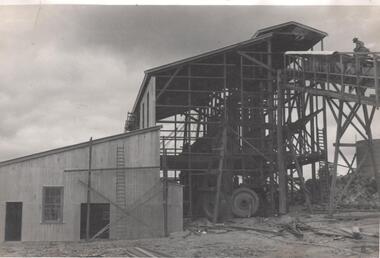
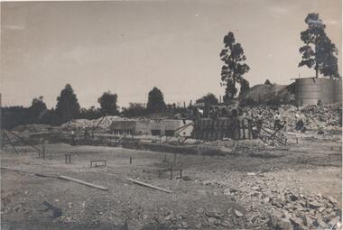
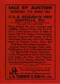
Document - IAN DYETT COLLECTION: AUCTION CATALOGUE - C.R.A. RESEARCH UNIT - EASTVILLE
... & P.V.C. Piping, Assorted Tools, Electrical and General Equipment..., Thousands of Metres H.D. Electrical Cable, Air Hose, Steel Flanged ...Red covered auction catalogue with black printing for a sale at C.R.A. Research Unit, Eastville, Vic on 27th March 1985. For sale was Pump Setting Rig skid mounted with 12,000 lbs. Thomas Winch with 5.5 K.W. 415 V. 3 HP Electric Motor & 100m of Cable, 1981 W.B. Holden 1 Tonne Utility, Massey Ferguson 290 Tractor, 75 KVA McFarlane Generator with 6 Cyl. Diesel Motor on Tandem Trailer, Alum. Site Workshop, Steel Ships Container, 2 Uniroyal Static Storage Tanks each 50,000 gallons (U.S.), 13 Groundfos Electric S.S. Submersible Pumps, Portacom Toilet, Thousands of Metres H.D. Electrical Cable, Air Hose, Steel Flanged, Drill & P.V.C. Piping, Assorted Tools, Electrical and General Equipment. J. H. Curnow & Son Pty. Ltd. Were the auctioneers.business, auctioneers, j h curnow & son pty ltd, ian dyett collection - auction catalogue - c.r.a. research unit - eastville vic, j h curnow & son pty ltd, f c dyett, i m dyett, n f dyett, bolton bros pty ltd print -
 Ballarat Tramway Museum
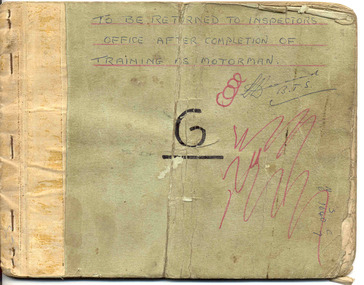
Book, State Electricity Commission of Victoria (SECV), Ballarat Motorman (Driver) Training Manual or Guide - not a formal title, 1960's?, 1950's?
... Equipment - electrical - items or clauses 1 to 28 (B) Location...: (A) Tramcar Equipment - electrical - items or clauses 1 to 28 (B ...Demonstrates aspects of the Ballarat Tramways system of training Motorman or drivers in the 1960's and the information there were given on driving trams. Shows the training methods of the time. 3486.1 - also details "Dead Man Brakes"Thirty Three page - carbon copy - within stapled light card covers - Ballarat Motorman (Driver) Training Manual or Guide - not a formal title. On front cover is large letter "G" and words "To be returned to the inspectors office after completion of Training as Motorman" First four pages has index and covers: (A) Tramcar Equipment - electrical - items or clauses 1 to 28 (B) Location of Faults - items 29 - 41 (C) Tramcar Braking - items 42 to 59 (D) Failure of the Mechanical Brakes - items 60 to 67 (E) Tramcar Emergency Braking (Accident Prevention) - items 68 - 72 (F) Automatic Electric Signals - items 73 - 82 - gives locations of signals. (G) General Instructions - items 83 to 98. See condition notes - not in the best condition - needs careful handling. 3486.4 - ditto - similar to above, but 34 pages through to instruction 104. Added section (F) after (E) - "Automatic Braking - clauses 72 - 79, possibly an earlier version of above when trams were fitted with dead man controls. Held within a cardboard folder with a metal binder. Cover has been covered with brown paper and adhesive tape, but only remains on the inside of the cover. Item added 3/10/2007. See Reg Item 8110i for a Bendigo, c1940 version.See above 3486.1 - has "Hall G - M.Cond" on front cover. Another name has been rubbed out.trams, tramways, driver training, sec, signals, braking, equipment, emergency, dead man controls -
 Ballarat Tramway Museum
Book, State Electricity Commission of Victoria (SECV), Instructions or Rules to Motormen, post 1945
... or instructions, covering Tramcar Equipment (electrical), location..., covering Tramcar Equipment (electrical), location of faults ...Handmade book with light green covers made from a cut file holder with brown paper glued on the inside, containing 39 typed (original) sheets of paper giving Instructions or Rules to Motormen. Has five page index, then 34 pages, with 104 rules or instructions, covering Tramcar Equipment (electrical), location of faults, tramcar braking, failure of the mechanical brakes, tramcar emergency braking, automatic braking, automatic electric signals and general instructions for Ballarat. The brown paper appears to have been placed on the outside, as it is cut and glued on the inside of the book. Individual sheets held into the book with a metal clip. On the rear of the book, a small piece of cardboard has been glued over the back of the metal strip. Notes mentions bogie trams, so therefore post 1945. Gives details of route electric signals, use of doors on the trams relevant to the central median strip. On page 4, has hand drawn diagram showing the motors in series and parallel. On page 8 has a hand drawn diagram showing the car lighting circuit arrangements. Has been folded in the middle so as to store in pockets of a coat. Images show .1 - book, .2 - inside front cover and index sheet, .3 - hand made drawing - car lighting circuit. See Destination Eaglehawktrams, tramways, secv rules, rules, motormen, conductors -
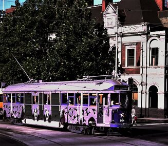 Ballarat Tramway Museum
Functional Object - Tramcar, Melbourne and Metropolitan Tramways Board (MMTB), Tramcar 504, 1928
... Workshops where the electrical and mechanical equipment was fitted... Workshops where the electrical and mechanical equipment was fitted ...A four motor bogie drop centre combination tram of the Melbourne W2 class. Body built by the James Moore and Co. of South Melbourne as a W2 class tram. Delivered to the MMTB Preston Workshops where the electrical and mechanical equipment was fitted. Issued to traffic 18/4/1928. Allocated to Essendon Depot. The tram was part of the Transporting Art project suggested by the artist Clifton Pugh (1924-1990) in Jan. 1978 to the Lord Mayor of Melbourne Cr. Irvin Rockman. The concept was enthusiastically supported by Victorian Premier Rupert Hamer. Clifton Pugh's tram was the second tram to appear. Described by the artist as "The apostle birds in flight, as if the tram has run into a group of them and they're flying along the sides. Then I found the route was to be through Collingwood and Hawthorn football territory and one cannot be one-eyed in that worlds, there are a magpie and a hawk on each side." The tram was retained by the State and stored until 2015 when it was transported to the Museum's Offsite store. Formal ownership was transferred to the Museum during 2019. Conservation planning for the tram's return to service and the restoration of the artwork is underway. 1986 - withdrawn from service following a minor accident and stored. In 2015 tram relocated to the Museum's offsite store and during 2019 transferred to ownership of the Museum. See btm.org.au/trams/504.html for further detail. Photos - i1 - Ray Marsh 1978 i2 - Alastair Reither - 3/6/2015 showing the damaged side. i3 - Clifton Pugh on board his tram. Photo from the Diners Club Signature Magazine April/May 1982, from an article titled Moving Masterpieces. Photo courtesy of the Melbourne Tram Museum. See Destination Citytrams, w2 class, transporting art, tram 504 -
 Bendigo Historical Society Inc.
Photograph - Napoleon Reef Gold Mine Battery Site, 1936
... lavish of Bendigo's mines. Plant and equipment were electrically... lavish of Bendigo's mines. Plant and equipment were electrically ...The Napoleon (BML) gold mine (1932) was located near McDougall Road, Golden Gully, between Martin and Hattam Street. It had a depth of 921 feet. It was one of the latest and most lavish of Bendigo's mines. Plant and equipment were electrically driven. The four-compartment shaft, extra large by goldfield's standards, measured 17 feet 6 inches by 5 feet 2 inches and was cement lined below 900 feet instead of being red gum boxed as was the usual practice. The workshop was equipped to carry out all repairs for the equally lavish BML mines on the Nell Gwynne and Carshalton reefs. (The Gold Mines of Bendigo, Book 2, Arthur Victor Palmer) 'Napoleon BML Mines No Liability have issued a report for the fortnight ended September 5, where it states that the development scheme has been formulated and necessary equipment is being ordered. The Napoleon main shaft, (about 1700 feet south of the old Napoleon shaft) will be a four compartment shaft (17ft 6 inches by ft 2 inches inside the timber). aLevels will be opened at approximately 100 ft vertical intervals and cross-cuts extended approximately 125 ft each side of centre country to explore a cross-section across the anticline opposite to the shaft. At every fifth level, main drives will be extended north to connect with the old Napoleon shaft and south approximately 1800 ft. At the latter point, another cross-section of the anticline will be explored by rising and cross-cutting. The old Napoleon will be unwatered and on the 500ft and 1000 ft levels main drives will be driven to connect with main levels from the Napoleon main shaft to the south as well as being driven north 1800 ft where another cross-section of the anticline will be explored. Cross-sections further north and south may be developed as desired and also at intermediate points if necessary. Clearing and grading of the main shaft site are now in progress and the erection of the office and store building is proceeding. The design of engine room, change house and machine shops is now in hand and erection will proceed as soon as working plans and specifications are prepared.' The main shaft has been commenced at 3ft and advanced 10 ft. to 13 ft. https://trove.nla.gov.au/newspaper/article/10975478?searchTerm=napoleon%20bml (The Argus, 8th. September 1934, 'Mining' page 18) Significant to mining history of Bendigo.Black and white photograph of a stamper head being lowered into position on the battery site of the Napoleon Reef Gold Mine. A wooden gantry supports the battery head as it being lowered. Three large concrete foundations are visible in immediate background, two of which have stampers already in position, the third stamper is being lowered onto the final foundation. In immediate foreground, 'boxing' is erected for future concrete pours. napoleon gold mine, napoleon reef gold mine -
 Phillip Island and District Historical Society Inc.
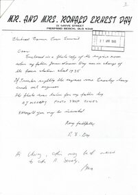
Photograph, Power station, Cowes 1930s, 1995
The Cowes Power station was in Cowes west, corner of Chapel Street and Osborne Avenue. James Norman Day was in charge c. 1935.HistoricalPhotocopy of letter from Mr & Mrs Ronald Day, Mermaid Beach, Queensland, sent to the Electrical Engineer, Cowes Council, 1995. and reply to sender. Also copy of photo of equipment in power station.Mr and Mrs Ronald Ernest Daypower station, electricity, james norman day -
 Orbost & District Historical Society
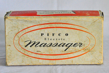
electric massager, PIFCO Ltd, 1947 - 1948
Lottie Bulmer (wife of Mr Frank Bulmer, Orbost) originally owned the massager. It was given to Di Cunningham by her sister Barbara who married Les Bulmer, Lottie and Frank's son,. After Les died, Barbara gave it to Di Cunningham, her sister, Di kept it for about a year. Pifco manufactured personal massaging equipment between 1948 and about 1968 (the first appeared about 1935).These devices were promoted as being able deal with all kinds of complaints, from headaches, pain relief and flatulence to hair loss and gout. It is an example of an early electrical appliance.3081.1 is an orange and white cardboard box - in black print on top is "PIFCO Electric Massager". It is the original container. Inside is an electric appliance with three attachable massage red coloured caps. There is an electric cord with a plug. The handle has ridges for gripping. There is a special control knob - possibly bakelite. There is a 15 pp instruction manual - 3081.3. Reg. no 852269massager pifco electrical-appliance bulmer