Showing 25 items matching "3d modelling"
-
 Vision Australia
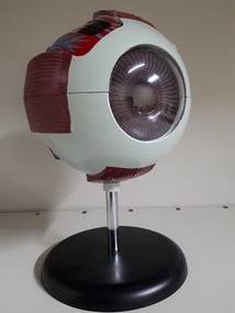
Education kit - Object, 3D model of eye
... 3D model of eye...This 3D model of the eye on shows the way they eye connects to the brain. ...1 pedestal mounted 3D model of the eye, hand painted in green, red, blue yellow and black ...Equipment Model 1 pedestal mounted 3D model of the eye, hand painted in green, red, blue yellow and black 3D model of eye Education kit Object ...This 3D model of the eye on shows the way they eye connects to the brain. The eyeball divides in half to study the interior and shows attachments for all six muscles that move the eyeball, the optic nerve, and surrounding blood vessels. Through the cornea the iris and pupil are visible. The iris, cornea and lens can be removed.1 pedestal mounted 3D model of the eye, hand painted in green, red, blue yellow and black equipment, model -
 City of Stonnington
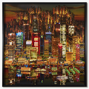
Stephen Haley, Dragon City, 2019
... ...3D Modelling...Stonnington contemporary art collection Stephen Haley City Digital 3D Modelling Virtual spaces Urbanisation Dragon City Stephen Haley ...Melbourne-based artist Stephen Haley explores the boundaries between actual and virtual spaces in an increasingly urbanised world. While Dragon City (2019) and it's accompanying artwork Inter City (2018) resemble traditional photographs of sweeping cityscapes, these artworks are camera-less ‘virtual photographs’ constructed using 3D digital modelling software. Haley, whose career spans two decades and 120 international exhibitions, uses technology to mirror the very tools urban planners employ to shape our physical world. By presenting simulated urban environments that feel familiar yet strangely impossible, Haley questions how digital technology alters human memory and perception. Both Inter City (2018) and Dragon City (2019) from his celebrated City Scape series offer a window into how our cities evolve, how we experience them, and perhaps most intriguingly, how they experience us.stonnington contemporary art collection, stephen haley, city, digital, 3d modelling, virtual spaces, urbanisation -
 City of Stonnington
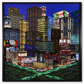
Stephen Haley, Inter City, 2018
... ...3D Modelling...Stonnington contemporary art collection Stephen Haley 3D Modelling Digital Urbanisation Virtual spaces Inter City Stephen Haley ...Melbourne-based artist Stephen Haley explores the boundaries between actual and virtual spaces in an increasingly urbanised world. While Inter City (2018) and it's accompanying artwork Dragon City (2019) resemble traditional photographs of sweeping cityscapes, these artworks are camera-less ‘virtual photographs’ constructed using 3D digital modelling software. Haley, whose career spans two decades and 120 international exhibitions, uses technology to mirror the very tools urban planners employ to shape our physical world. By presenting simulated urban environments that feel familiar yet strangely impossible, Haley questions how digital technology alters human memory and perception. Both Inter City (2018) and Dragon City (2019), from his celebrated City Scape series, offer a window into how our cities evolve, how we experience them, and perhaps most intriguingly, how they experience us.stonnington contemporary art collection, stephen haley, 3d modelling, digital, urbanisation, virtual spaces -
 Stawell Historical Society Inc
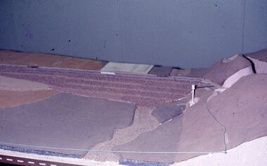
Slide, Ian McCann, Constructing Lake Bellfield
... 3d Model of lake Bellfield...Stawell Historical Society Inc 46 Longfield St Stawell grampians Lake Bellfield 3d Model of lake Bellfield Constructing Lake Bellfield Slide Ian McCann ...3d Model of lake Bellfieldlake bellfield -
 Port Fairy Historical Society Museum and Archives
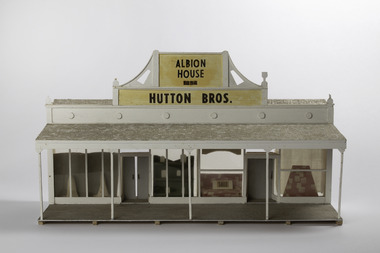
Mixed media - Model, Albion House, early 1970`s
... Small hand made 3D model of a shop front from the 1892 Almanac...Small hand made 3D model of a shop front from the 1892 Almanac Albion House Mixed media Model ...This model was part of a panorama of 11 pieces designed from drawings in an 1892 almanac Printed by Port Fairy Gazette. The panorama was used in the History Society rooms in Bank St Port Fairy on an extended mantel piece, before the Museum and Archives were relocated to Gipps Street Port FairyThis model was made as a part of an eleven piece panorama of the streetscape of Port Fairy in 1892. By a local resident of the town.Small hand made 3D model of a shop front from the 1892 AlmanacAlbion House 1854 Hutton Bros.sackville street, model, mewkill, almanac, albion house, bank street -
 Robin Boyd Foundation
Decorative object - Model of Tower Hill Natural History Centre, 2017
... 3D timber model of the Tower Hill landscape...This model was created for the House of Ideas exhibition, made by a University of Melbourne, Melbourne School of Design, Masters student. robin boyd 3D timber model of the Tower Hill landscape Decorative object Model of Tower Hill Natural History Centre ...This is a model of the Robin Boyd-designed Tower Hill Natural History Centre, Tower Hill, near Warrnambool, Victoria (1963). It was opened shortly after Robin Boyd died in November 1971. The Archive also holds some of the original architectural drawings (item PL136-P145). This model was created for the House of Ideas exhibition, made by a University of Melbourne, Melbourne School of Design, Masters student.3D timber model of the Tower Hill landscaperobin boyd -
 Royal Australian and New Zealand College of Obstetricians & Gynaecologists (RANZCOG)
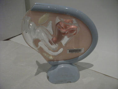
Teaching model, female reproduction organs, 1940s-1950s
... Teaching model- 3D Female Reproduction Organs on stand. ...Royal Australian and New Zealand College of Obstetricians & Gynaecologists (RANZCOG) 1 Bowen Crescent Naarm (Melbourne) melbourne Originally this teaching model belonged to Prince Henry's hospital library and was transferred to the Monash Medical Centre, Clayton in the 1970s by Sister Gertrude Berger, a famous nurse-educator, who is best known for her work leading up to the transfer of nursing education in Victoria from hospitals to universities in 1986.Gerty (as she was known in the School of Nursing) bought them in Europe in the late 1940s and early 1950s. teaching model anatomy female reproduction organs Teaching model- 3D Female Reproduction Organs on stand. ...Originally this teaching model belonged to Prince Henry's hospital library and was transferred to the Monash Medical Centre, Clayton in the 1970s by Sister Gertrude Berger, a famous nurse-educator, who is best known for her work leading up to the transfer of nursing education in Victoria from hospitals to universities in 1986.Gerty (as she was known in the School of Nursing) bought them in Europe in the late 1940s and early 1950s.Teaching model- 3D Female Reproduction Organs on stand. Plastic. Demonstration model for the insertion of cervical diaphragm. Manufacturer: Ortho, New Jersey. Barcode label Monash Medical Centre Clayton.teaching model, anatomy, female reproduction organs -
 Royal Australian and New Zealand College of Obstetricians & Gynaecologists (RANZCOG)
Teaching model, female reproduction organs, 1940s-1950s
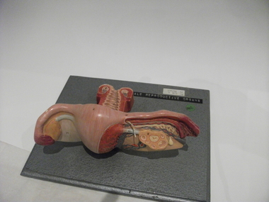
... Teaching model- 3D Female Reproduction Organs Painted and numbered plastic mould, showing vagina and one ovary and fallopian tube in cross-section. ...Royal Australian and New Zealand College of Obstetricians & Gynaecologists (RANZCOG) 1 Bowen Crescent Naarm (Melbourne) melbourne Originally this teaching model belonged to Prince Henry's hospital library and was transferred to the Monash Medical Centre, Clayton in the 1970s by Sister Gertrude Berger, a famous nurse-educator, who is best known for her work leading up to the transfer of nursing education in Victoria from hospitals to universities in 1986.Gerty (as she was known in the School of Nursing) bought them in Europe in the late 1940s and early 1950s. teaching model anatomy female reproduction organs Teaching model- 3D Female Reproduction Organs Painted and numbered plastic mould, showing vagina and one ovary and fallopian tube in cross-section. ...Originally this teaching model belonged to Prince Henry's hospital library and was transferred to the Monash Medical Centre, Clayton in the 1970s by Sister Gertrude Berger, a famous nurse-educator, who is best known for her work leading up to the transfer of nursing education in Victoria from hospitals to universities in 1986.Gerty (as she was known in the School of Nursing) bought them in Europe in the late 1940s and early 1950s.Teaching model- 3D Female Reproduction Organs Painted and numbered plastic mould, showing vagina and one ovary and fallopian tube in cross-section. The model is mounted on a metallic grey painted timber panel. Manufacturer Adam Rouilly, London. label on lower right.]. Monash Medical Centre Clayton.teaching model anatomy, female reproduction organs -
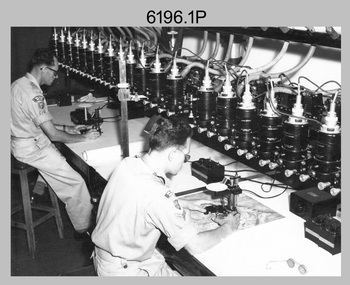 Bendigo Military Museum
Photograph - Multiplex mechanical stereoplotting equipment, Army Survey Regiment, Fortuna Bendigo, c1950s
... The technicians operated the Multiplex in a darkened room, with one photo projected with a green filter and the other through a red filter to form a 3D view of the overlapping photos. The 3D model projected onto a platen, which was a small platform that was raised up and down. ...The technicians operated the Multiplex in a darkened room, with one photo projected with a green filter and the other through a red filter to form a 3D view of the overlapping photos. The 3D model projected onto a platen, which was a small platform that was raised up and down. ...This is a set of five photographs of Multiplex mechanical stereoplotting equipment at the Army Survey Regiment, Fortuna Bendigo. c1950s. Multiplex equipment was imported from the UK in 1951 and introduced in the following year, to accelerate map production output covering CMF training areas at 1:25,000 map scale. Multiplex plotting was a productive advancement replacing the ‘Arundel’ method of graphical plotting planimetric detail that was expensive and slow, especially in timbered mountainous terrain. Air photos were made into small diapositives and mounted on racks in the exact position relative to when the aerial photos were taken. The technicians operated the Multiplex in a darkened room, with one photo projected with a green filter and the other through a red filter to form a 3D view of the overlapping photos. The 3D model projected onto a platen, which was a small platform that was raised up and down. The technician viewed the 3D image with special glasses fitted with red and green lenses. In the centre of the platen was a small pinhole that served as a floating mark, with a vertical pencil located exactly below the pinhole. This tracing table was moved to follow the topographic feature or contour line and draw it on the paper underneath. The technician raising or lowering the platform’s floating mark to match the height of the 3D terrain. It also replaced the slotted template method of mechanical adjustment of strips of aerial photography, however was restricted to each strip rather than between strips in the block. Although the Multiplex was phased out of production in 1968, it was used in the training of photogrammetry and aero-triangulation at the School of Military Survey located at Bonegilla, Victoria until the early 1990s. The history of the Multiplex is covered in more detail with additional historic photographs, in pages 50 to 51 of Valerie Lovejoy’s book 'Mapmakers of Fortuna – A history of the Army Survey Regiment’ ISBN: 0-646-42120-4.This is a set of five photographs of Multiplex mechanical stereoplotting equipment at the Army Survey Regiment, Fortuna, Bendigo. c1950s. The photographs were printed on photographic paper and are part of the Army Survey Regiment’s Collection. The photographs were scanned at 300 dpi. .1) - Photo, black & white, c1950s, unidentified personnel operating Multiplex equipment. .2) - Photo, black & white, c1950s, Multiplex equipment. .3) - Photo, black & white, c1950s, Multiplex components identified. .4) - Photo, black & white, c1950s, Multiplex optical components. .5) - Photo, black & white, c1950s. Unidentified technician laying down individual Multiplex plots..1P to .2P, .4P – No annotations. .3P annotations identifying Multiplex components on front of photo. .5P annotated on front ‘Lay down of individual Multiplex plots at 1/14000 to framework of master grid to form Composite Compilation Sheet – Material Duralex.’royal australian survey corps, rasvy, army survey regiment, army svy regt, fortuna, asr, photogrammetry -
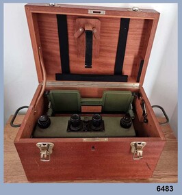 Bendigo Military Museum
Instrument - Old Delft Scanning Stereoscope ODSS III, C. 1956
... This instrument has a particularly useful capability to scan over the 3D stereo model using X and Y movement knobs, rather than having to physically move the aerial photographs. ...This instrument has a particularly useful capability to scan over the 3D stereo model using X and Y movement knobs, rather than having to physically move the aerial photographs. ...This is a superbly crafted cartographic mapping instrument. It is housed in its own high-quality purpose-built oak box. Made in the Netherlands from 1950 onwards. This instrument is from c 1956. it is a very high-quality military grade stereoscope that was generally used by photographic interpreters such as intelligence analysts but was equally useful for mapping activities. The stereoscope was used to examine 3D aerial photographic images. This instrument has a particularly useful capability to scan over the 3D stereo model using X and Y movement knobs, rather than having to physically move the aerial photographs. In the public and private sector it was also useful for photogrammetric interpretation for Forestry and Agricultural purposes. See also Bendigo RSL Collections Victoria item Number 6205.6P that shows the Old Deft Stereoscope in use at the Army Survey Regiment, Bendigo.This is an "Old Delft" scanning stereoscope with its reflecting carriage and legs. The Stereoscope is housed in its own purpose built wooden oak box that has dovetail joints, 2 x securing clips, 2 x handles and a lock (without key). The instrument is assembled by inserting colour coded legs into their matching slots."OLD DELFT SCANNING STEREOSCOPE ODSS III" "Patents Applied for" "OLD DELFT C4790" "MADE IN THE NETHERLANDS"royal australian survey corps, rasvy, fortuna, army survey regiment, army svy regt, asr -
 Bendigo Military Museum
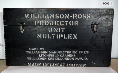
Instrument - Multiplex Unit Projector, Williamson Manufacturing Co, Circa 1950
... The technicians operated the Multiplex in a darkened room, with one photo projected with a green filter and the other through a red filter to form a 3D view of the overlapping photos. The 3D model projected onto a platen, which was a small platform that was raised up and down. ...The technicians operated the Multiplex in a darkened room, with one photo projected with a green filter and the other through a red filter to form a 3D view of the overlapping photos. The 3D model projected onto a platen, which was a small platform that was raised up and down. ...Multiplex mechanical stereoplotting equipment was used at the Army Survey Regiment, Fortuna Bendigo. c1950s. Multiplex equipment was imported from the UK in 1951 and introduced in the following year, to accelerate map production output covering CMF training areas at 1:25,000 map scale. Multiplex plotting was a productive advancement replacing the ‘Arundel’ method of graphical plotting planimetric detail that was expensive and slow, especially in timbered mountainous terrain. Air photos were made into small diapositives and mounted on racks in the exact position relative to when the aerial photos were taken. The technicians operated the Multiplex in a darkened room, with one photo projected with a green filter and the other through a red filter to form a 3D view of the overlapping photos. The 3D model projected onto a platen, which was a small platform that was raised up and down. The technician viewed the 3D image with special glasses fitted with red and green lenses. In the centre of the platen was a small pinhole that served as a floating mark, with a vertical pencil located exactly below the pinhole. This tracing table was moved to follow the topographic feature or contour line and draw it on the paper underneath. The technician raising or lowering the platform’s floating mark to match the height of the 3D terrain. It also replaced the slotted template method of mechanical adjustment of strips of aerial photography, however was restricted to each strip rather than between strips in the block. Although the Multiplex was phased out of production in 1968, it was used in the training of photogrammetry and aero-triangulation at the School of Military Survey located at Bonegilla, Victoria until the early 1990s. The history of the Multiplex is covered in more detail with additional historic photographs, in pages 50 to 51 of Valerie Lovejoy’s book 'Mapmakers of Fortuna – A history of the Army Survey Regiment’ ISBN: 0-646-42120-4. This instrument is only one of the projectors of a set and is unfortunately missing its platen, coloured filters and coloured glasses. Another instrument is in the collection as Item 9039.4A black wooden box containing a Multiplex Unit Projector (incomplete). The Multiplex has a Lamp Head, Barrel Housing, Body of the Projector and a Platen which is missing. .1 Protective wooden box .2 Multiplex Instrument .3 Multiplex Instrument Parts Diagram .4 A bank of Multiplex projectors in operation WILLIAMSON MANUFACTURING CO, PHOTOGRAPHIC ENGINEERS, SERIAL NUMBER 3437, TYPE MPC, LITCHFIELD GARDENS, LONDON AND READING.royal australian survey corps, rasvy, fortuna, army survey regiment, army svy regt -
 Bendigo Military Museum
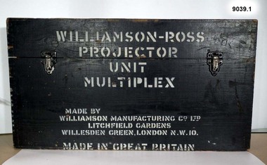
Instrument - Multiplex Unit Projector, Williamson Manufacturing Co, Circa 1950
... The technicians operated the Multiplex in a darkened room, with one photo projected with a green filter and the other through a red filter to form a 3D view of the overlapping photos. The 3D model projected onto a platen, which was a small platform that was raised up and down. ...The technicians operated the Multiplex in a darkened room, with one photo projected with a green filter and the other through a red filter to form a 3D view of the overlapping photos. The 3D model projected onto a platen, which was a small platform that was raised up and down. ...Multiplex mechanical stereoplotting equipment was used at the Army Survey Regiment, Fortuna Bendigo. c1950s. Multiplex equipment was imported from the UK in 1951 and introduced in the following year, to accelerate map production output covering CMF training areas at 1:25,000 map scale. Multiplex plotting was a productive advancement replacing the ‘Arundel’ method of graphical plotting planimetric detail that was expensive and slow, especially in timbered mountainous terrain. Air photos were made into small diapositives and mounted on racks in the exact position relative to when the aerial photos were taken. The technicians operated the Multiplex in a darkened room, with one photo projected with a green filter and the other through a red filter to form a 3D view of the overlapping photos. The 3D model projected onto a platen, which was a small platform that was raised up and down. The technician viewed the 3D image with special glasses fitted with red and green lenses. In the centre of the platen was a small pinhole that served as a floating mark, with a vertical pencil located exactly below the pinhole. This tracing table was moved to follow the topographic feature or contour line and draw it on the paper underneath. The technician raising or lowering the platform’s floating mark to match the height of the 3D terrain. It also replaced the slotted template method of mechanical adjustment of strips of aerial photography, however was restricted to each strip rather than between strips in the block. Although the Multiplex was phased out of production in 1968, it was used in the training of photogrammetry and aero-triangulation at the School of Military Survey located at Bonegilla, Victoria until the early 1990s. The history of the Multiplex is covered in more detail with additional historic photographs, in pages 50 to 51 of Valerie Lovejoy’s book 'Mapmakers of Fortuna – A history of the Army Survey Regiment’ ISBN: 0-646-42120-4. This instrument is only one of the projectors of a set and is unfortunately missing its coloured filters and coloured glasses. Another instrument is in the collection as Item 9003.4A black wooden box containing a Multiplex Unit Projector (incomplete). The Multiplex has a Lamp Head, Barrel Housing, Body of the Projector and a Platen. .1 Protective wooden box .2 Multiplex Instrument .3 Multiplex Instrument Parts Diagram .4 A bank of Multiplex projectors in operation WILLIAMSON MANUFACTURING CO, PHOTOGRAPHIC ENGINEERS, SERIAL NUMBER 3187, TYPE MPC, LITCHFIELD GARDENS, LONDON AND READING.royal australian survey corps, rasvy, fortuna, army survey regiment, army svy regt -
 Bendigo Military Museum
Photograph - AUTOMAP 2 Production and Digital Topographic Data - Army Survey Regiment, Fortuna, Bendigo, c1990
... They are part of the Army Survey Regiment’s Collection. .1) - Photo, colour, c1990, AUTOMAP 2 Wild B8 Aviograph stereoplotter. .2) - Photo, colour, c1990, Four Wild B8 Aviograph stereoplotters, data storage tapes in foreground. .3) - Photo, colour, c1990, AUTOMAP 2 Graphic Edit Workstation. .4) - Photo, colour, c1990, AUTOMAP 2 - cultural digital data. .5) - Photo, colour, c1990, AUTOMAP 2 - drainage and cultural digital data. .6) - Photo, colour, c1990, AUTOMAP 2 - drainage and cultural digital data, enlargement of previous view. .7) - Photo, colour, c1990, AUTOMAP 2 - contour digital data. .8) - Photo, colour, c1990, AUTOMAP 2 - contour digital data with coloured elevation tints. .9) & .10) - Photo, colour, c1990, AUTOMAP 2 - perspective view of 3D digital terrain model. .11) & .12) - Photo, colour, c1990, AUTOMAP 2 – low profile view of 3D digital terrain model. .13) & .14) - Photo, colour, c1990, AUTOMAP 2 – line of sight view sheds from defined point. .15) & .16) - Photo, colour, c1990, AUTOMAP 2 – analytical hill shading samples generated from 3D digital terrain model....They are part of the Army Survey Regiment’s Collection. .1) - Photo, colour, c1990, AUTOMAP 2 Wild B8 Aviograph stereoplotter. .2) - Photo, colour, c1990, Four Wild B8 Aviograph stereoplotters, data storage tapes in foreground. .3) - Photo, colour, c1990, AUTOMAP 2 Graphic Edit Workstation. .4) - Photo, colour, c1990, AUTOMAP 2 - cultural digital data. .5) - Photo, colour, c1990, AUTOMAP 2 - drainage and cultural digital data. .6) - Photo, colour, c1990, AUTOMAP 2 - drainage and cultural digital data, enlargement of previous view. .7) - Photo, colour, c1990, AUTOMAP 2 - contour digital data. .8) - Photo, colour, c1990, AUTOMAP 2 - contour digital data with coloured elevation tints. .9) & .10) - Photo, colour, c1990, AUTOMAP 2 - perspective view of 3D digital terrain model. .11) & .12) - Photo, colour, c1990, AUTOMAP 2 – low profile view of 3D digital terrain model. .13) & .14) - Photo, colour, c1990, AUTOMAP 2 – line of sight view sheds from defined point. .15) & .16) - Photo, colour, c1990, AUTOMAP 2 – analytical hill shading samples generated from 3D digital terrain model. ...This collection of 16 photos of map production on the AUTOMAP 2 computer-based system in Air Survey and Cartographic Squadrons, was most likely taken in 1990. The AUTOMAP 2 system was an upgrade to the AUTOMAP 1 system, comprising Intergraph graphic edit workstation terminals networked to VAX 750/785 main frame computers. Unlike AUTOMAP 1, operators could display digital topographic features on monitors for editing. Successful adaptation of this system meant RASvy was at the forefront of digital mapping/cartographic systems in Australia and overseas. The system comprised Input (Wild B8 Aviograph feature extraction) Raster Scanning (digitising from compilation sheets, Graphic Edit (cartographic completion) and Plot Verification Sub Systems. The system was operational from 1984 to its ‘Newheart’ upgrade in 1993. Throughout its life, the system was progressively refined with productivity gains, achieved from award winning technical development in-house by talented and innovative Army Survey Regiment personnel. Refer to Item 6223.23P for more photos of the AUTOMAP 2 System and examples of topographic digital data. Additional information on topographic digital data and its use in military operations is provided in the video included in Item 6010 titled An Introduction to Topographic Mapping circa 1991.This is a set of 16 photograph of AUTOMAP 2 production at the Army Survey Regiment at Fortuna, Bendigo, c1990. The photographs are on 35mm colour positive film and scanned at 2400 dpi. They are part of the Army Survey Regiment’s Collection. .1) - Photo, colour, c1990, AUTOMAP 2 Wild B8 Aviograph stereoplotter. .2) - Photo, colour, c1990, Four Wild B8 Aviograph stereoplotters, data storage tapes in foreground. .3) - Photo, colour, c1990, AUTOMAP 2 Graphic Edit Workstation. .4) - Photo, colour, c1990, AUTOMAP 2 - cultural digital data. .5) - Photo, colour, c1990, AUTOMAP 2 - drainage and cultural digital data. .6) - Photo, colour, c1990, AUTOMAP 2 - drainage and cultural digital data, enlargement of previous view. .7) - Photo, colour, c1990, AUTOMAP 2 - contour digital data. .8) - Photo, colour, c1990, AUTOMAP 2 - contour digital data with coloured elevation tints. .9) & .10) - Photo, colour, c1990, AUTOMAP 2 - perspective view of 3D digital terrain model. .11) & .12) - Photo, colour, c1990, AUTOMAP 2 – low profile view of 3D digital terrain model. .13) & .14) - Photo, colour, c1990, AUTOMAP 2 – line of sight view sheds from defined point. .15) & .16) - Photo, colour, c1990, AUTOMAP 2 – analytical hill shading samples generated from 3D digital terrain model.There are no annotations.royal australian survey corps, rasvy, army survey regiment, army svy regt, fortuna, automap 2 -
 Bendigo Military Museum
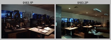
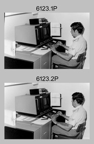
photograph - Cartographic Squadron Production – Army Survey Regiment, Fortuna, c1980
... Ridge lines were then pushed down using the contour impression as a guide, on the opposing side of the AK Poligraphy to create a 3D plastic model terrain effect. The map impression was sprayed with white paint and photographed to create a contone tone hill shade. ...Ridge lines were then pushed down using the contour impression as a guide, on the opposing side of the AK Poligraphy to create a 3D plastic model terrain effect. The map impression was sprayed with white paint and photographed to create a contone tone hill shade. ...This collection of 12 photos was most likely taken in 1980. The photos were most likely taken in Cartographic Squadron’s Ante Room, the Attic and small offices on the top floor of Fortuna Villa. The computer based Editwriter typesetting system was introduced in 1975 as a replacement to the aging Fotosetter machine. It was operated by a specialised technician, who generated a large variety of map type styles and sizes quickly and reliably, as well as text panels. CPL Richards performed this task for several years and in photo .1P and .2P is reading off a type order next to the computer monitor. Output on Copy proof adhesive backed stripping type film replaced messy wax and spray adhesives in 1978. The Editwriter capability supported all RASvy units and contractor type setting requirements. Scribing was the cartographic process of drafting features such as drainage, relief, vegetation, roads and culture on specially coated map reproduction material. The cartographic technician scribed out the map feature such as a contour to a specified line width on the map sheet, using a tool affixed with a sapphire tipped cutter. The quality control edit (Proving) stage of map production was the first opportunity to inspect a proof of the map independently and systematically. Proving tasks were carried out by technicians conversant of the map product specification and task requirement, however, was not involved in its production. Corrections were identified, marked up and sent to back to the correcting section or contractors. Terrain Embossing was a manual map production technique to produce hill shading on medium to small scale graphics and air charts. SPR John Martin is seen in photos .8P to.10P using a fine embossing metal stylus to push down on the drainage impression on a thin malleable opaque plastic material (AK Poligraphy). Ridge lines were then pushed down using the contour impression as a guide, on the opposing side of the AK Poligraphy to create a 3D plastic model terrain effect. The map impression was sprayed with white paint and photographed to create a contone tone hill shade. SPR Gina (Coore) Neilson is seen in photo .11P washing a contone positive of a land mass in a solution. The contone components were registered to the map sheet, as shown in photo .12P and masked using an air brush and a halftone negative was then created. The terrain embossing method of producing hill shading was more efficient to produce than previous specialised artistic methods such pencil/eraser and air brush. Furthermore, a more consistent enhancement of terrain on charts was achieved between technicians.This is a set of 12 photographs of Cartographic Squadron performing four map production tasks at the Army Survey Regiment, Fortuna, Bendigo c1980. The first ten photographs were on 35mm negative film and were scanned at 96 dpi. Photos .11P and .12P were on photographic paper and scanned at 300 dpi. They are part of the Army Survey Regiment’s Collection. .1) - Photo, black & white, c1980, Editwriter typesetter, CPL Paul Richards. .2) - Photo, black & white, c1980, Editwriter typesetter, CPL Paul Richards. .3) - Photo, black & white, c1980, Scribing contours on a RAAF Chart, SPR Megan (McBurney) Reynolds. .4) - Photo, black & white, c1980, Scribing contours on a RAAF Chart, SPR Megan (McBurney) Reynolds. .5) - Photo, black & white, c1980, Scribing contours on a RAAF Chart, SPR Rod Skidmore. .6) - Photo, black & white, c1980, Scribing contours on a RAAF Chart, SPR Rod Skidmore. .7) - Photo, black & white, c1980, Formal quality control edit (Proving), CPL Ian Belmont. .8) - Photo, black & white, c1980, Hill Shade Terrain Embossing, SPR John Martin. .9) - Photo, black & white, c1980, Hill Shade Terrain Embossing, SPR John Martin. .10) - Photo, black & white, c1980, Hill Shade Terrain Embossing, SPR John Martin. .11) - Photo, black & white, c1980, Hill Shade Terrain Embossing, SPR Gina (Coore) Neilson. .12) - Photo, black & white, c1980, Hill Shade Terrain Embossing, unidentified..1P to .10P No personnel are identified. .11P and .12P annotated ‘Terrain Embossing’royal australian survey corps, rasvy, army survey regiment, army svy regt, fortuna, asr, carto -
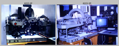 Bendigo Military Museum
Photograph - AUTOMAP 2 Production - Army Survey Regiment, Fortuna, Bendigo, c1986
... They are part of the Army Survey Regiment’s Collection. .1) - Photo, colour, c1986, AUTOMAP 2 Production - Army Survey Regiment, Fortuna, Bendigo. c1986. .2) - Photo, colour, c1986, AUTOMAP 2 Wild B8 Aviograph stereoplotter. .3) - Photo, colour, c1986, AUTOMAP 2 Wild B8 Aviograph stereoplotter feature extraction, unidentified technician. .4) - Photo, colour, c1986, Wild B8 Aviograph stereoplotter feature extraction, LCPL Raelene (Munting) Brodie. .5) - Photo, colour, c1986, AUTOMAP 2 computer tape maintenance, SPR Steve Linane. .6) - Photo, colour, c1986, AUTOMAP 2 Graphic Edit Workstation, SPR Steve Linane. .7) to .8) - Photo, colour, c1986, AUTOMAP 2 Graphic Edit Workstation, unidentified technician. .9 to .10) - Photo, colour, c1986, AUTOMAP 2 Graphic Edit Workstation. .11) - Photo, colour, c1986, AUTOMAP 2 Graphic Edit Workstation feature coding and command menu. .12) - Photo, colour, c1986, AUTOMAP 2 high resolution computer monitor. .13) to .16) - Photo, colour, c1986, AUTOMAP 2 production output comparison to AUTOMAP 1. .17) to .18) - Photo, colour, c1986, AUTOMAP 2 computer system components. .19) - Photo, colour, c1986, AUTOMAP 2 Intergraph 7596 verification plotter. .20) - Photo, colour, c1986, AUTOMAP 2 Benson verification plotter, SPR Steve Coulson. .21) - Photo, colour, c1986, AUTOMAP 2 drainage, contour, roads and cultural digital data verification plot. .22) - Photo, colour, c1986, AUTOMAP 2 drainage, contour, roads and cultural digital data on computer monitor. .23) - Photo, colour, c1986, AUTOMAP 2 3D digital terrain model on computer monitor. ...They are part of the Army Survey Regiment’s Collection. .1) - Photo, colour, c1986, AUTOMAP 2 Production - Army Survey Regiment, Fortuna, Bendigo. c1986. .2) - Photo, colour, c1986, AUTOMAP 2 Wild B8 Aviograph stereoplotter. .3) - Photo, colour, c1986, AUTOMAP 2 Wild B8 Aviograph stereoplotter feature extraction, unidentified technician. .4) - Photo, colour, c1986, Wild B8 Aviograph stereoplotter feature extraction, LCPL Raelene (Munting) Brodie. .5) - Photo, colour, c1986, AUTOMAP 2 computer tape maintenance, SPR Steve Linane. .6) - Photo, colour, c1986, AUTOMAP 2 Graphic Edit Workstation, SPR Steve Linane. .7) to .8) - Photo, colour, c1986, AUTOMAP 2 Graphic Edit Workstation, unidentified technician. .9 to .10) - Photo, colour, c1986, AUTOMAP 2 Graphic Edit Workstation. .11) - Photo, colour, c1986, AUTOMAP 2 Graphic Edit Workstation feature coding and command menu. .12) - Photo, colour, c1986, AUTOMAP 2 high resolution computer monitor. .13) to .16) - Photo, colour, c1986, AUTOMAP 2 production output comparison to AUTOMAP 1. .17) to .18) - Photo, colour, c1986, AUTOMAP 2 computer system components. .19) - Photo, colour, c1986, AUTOMAP 2 Intergraph 7596 verification plotter. .20) - Photo, colour, c1986, AUTOMAP 2 Benson verification plotter, SPR Steve Coulson. .21) - Photo, colour, c1986, AUTOMAP 2 drainage, contour, roads and cultural digital data verification plot. .22) - Photo, colour, c1986, AUTOMAP 2 drainage, contour, roads and cultural digital data on computer monitor. .23) - Photo, colour, c1986, AUTOMAP 2 3D digital terrain model on computer monitor. AUTOMAP 2 Production - Army Survey Regiment, Fortuna, Bendigo. ...This collection of 23 photos of map production on the AUTOMAP 2 computer-based system in Air Survey and Cartographic Squadrons, was most likely taken in 1986. The AUTOMAP 2 system was an upgrade to the AUTOMAP 1 system, comprising Intergraph graphic edit workstation terminals networked to VAX 750/785 main frame computers. Unlike AUTOMAP 1, operators could display digital topographic features on monitors for editing. Successful adaptation of this system meant RASvy was at the forefront of digital mapping/cartographic systems in Australia and overseas. The system comprised Input (Wild B8 Aviograph feature extraction) Raster Scanning (digitising from compilation sheets, Graphic Edit (cartographic completion) and Plot Verification Sub Systems. The system was operational from 1984 to its ‘Newheart’ upgrade in 1993. Throughout its life, the system was progressively refined with productivity gains, achieved from award winning technical development in-house by talented and innovative Army Survey Regiment personnel.This is a set of 23 photograph of AUTOMAP 2 production at the Army Survey Regiment at Fortuna, Bendigo, c1986. The photographs were on 35mm colour slides and were scanned at 96 dpi. Photos .5P and .6P are also printed on photographic and scanned at 300 dpi. They are part of the Army Survey Regiment’s Collection. .1) - Photo, colour, c1986, AUTOMAP 2 Production - Army Survey Regiment, Fortuna, Bendigo. c1986. .2) - Photo, colour, c1986, AUTOMAP 2 Wild B8 Aviograph stereoplotter. .3) - Photo, colour, c1986, AUTOMAP 2 Wild B8 Aviograph stereoplotter feature extraction, unidentified technician. .4) - Photo, colour, c1986, Wild B8 Aviograph stereoplotter feature extraction, LCPL Raelene (Munting) Brodie. .5) - Photo, colour, c1986, AUTOMAP 2 computer tape maintenance, SPR Steve Linane. .6) - Photo, colour, c1986, AUTOMAP 2 Graphic Edit Workstation, SPR Steve Linane. .7) to .8) - Photo, colour, c1986, AUTOMAP 2 Graphic Edit Workstation, unidentified technician. .9 to .10) - Photo, colour, c1986, AUTOMAP 2 Graphic Edit Workstation. .11) - Photo, colour, c1986, AUTOMAP 2 Graphic Edit Workstation feature coding and command menu. .12) - Photo, colour, c1986, AUTOMAP 2 high resolution computer monitor. .13) to .16) - Photo, colour, c1986, AUTOMAP 2 production output comparison to AUTOMAP 1. .17) to .18) - Photo, colour, c1986, AUTOMAP 2 computer system components. .19) - Photo, colour, c1986, AUTOMAP 2 Intergraph 7596 verification plotter. .20) - Photo, colour, c1986, AUTOMAP 2 Benson verification plotter, SPR Steve Coulson. .21) - Photo, colour, c1986, AUTOMAP 2 drainage, contour, roads and cultural digital data verification plot. .22) - Photo, colour, c1986, AUTOMAP 2 drainage, contour, roads and cultural digital data on computer monitor. .23) - Photo, colour, c1986, AUTOMAP 2 3D digital terrain model on computer monitor. .1P to .23P - Some of the equipment is annotated on the frame of the 35mm slides. .5P & .6P prints annotated incorrectly ‘Steve Lenane’. Correct spelling is - ‘Steve Linane’ royal australian survey corps, rasvy, army survey regiment, army svy regt, fortuna, asr, automap 2 -
 Royal Australian and New Zealand College of Obstetricians & Gynaecologists (RANZCOG)
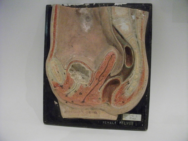
Teaching model, female pelvis, 1940s-1950s
... Teaching model. Female Pelvis, cross section, flat 3D panel. Painted plaster on painted timber. ...Royal Australian and New Zealand College of Obstetricians & Gynaecologists (RANZCOG) 1 Bowen Crescent Naarm (Melbourne) melbourne Originally this teaching model belonged to Prince Henry's hospital library and was transferred to the Monash Medical Centre, Clayton in the 1970s by Sister Gertrude Berger, a famous nurse-educator, who is best known for her work leading up to the transfer of nursing education in Victoria from hospitals to universities in 1986.Gerty (as she was known in the School of Nursing) bought them in Europe in the late 1940s and early 1950s. teaching model anatomy female pelvis Teaching model. Female Pelvis, cross section, flat 3D panel. Painted plaster on painted timber. ...Originally this teaching model belonged to Prince Henry's hospital library and was transferred to the Monash Medical Centre, Clayton in the 1970s by Sister Gertrude Berger, a famous nurse-educator, who is best known for her work leading up to the transfer of nursing education in Victoria from hospitals to universities in 1986.Gerty (as she was known in the School of Nursing) bought them in Europe in the late 1940s and early 1950s.Teaching model. Female Pelvis, cross section, flat 3D panel. Painted plaster on painted timber. Originally from Prince Henry's Hospital Nurses Library [ traces of stamp "PRINCE HENRYS HOSPITAL NURSES LIBRARY" on l.l.].teaching model, anatomy, female pelvis -
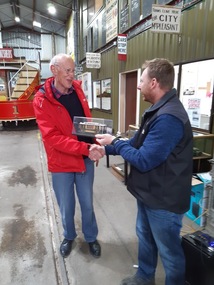 Ballarat Tramway Museum
Photograph - Digital image, Greg King, 27/10/2019 12:00:00 AM
... The model was made by Greg King and an associate - mainly 3D printed....The model was made by Greg King and an associate - mainly 3D printed. Photograph Digital image Greg King ...Set of two digital images of Paul Mong and Warrington Cameron receiving a model of Geelong No. 27/10/2019 at the BTM AGM. The model was made by Greg King and an associate - mainly 3D printed.trams, tramways, btm, geelong, models, agm -
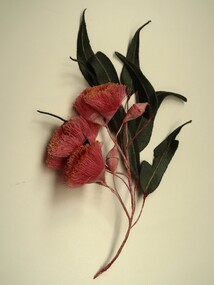 Embroiderers Guild, Victoria
Textile - 3D botanical embroidery of Silver princess eucalyptus, Lynne Stone, 2025
... Australian native flora flora Botanical model of Eucalyptus Caesia "Silver Princess" in flower with open flowers, flower buds and leaves. Embroidered using machine embroidery on an organza base. Wrapped wires and hand embroidered elements, hand coloured. Textile 3D ...Lynne Stone is a Victorian based textile artist specialising in botanical embroideries of Australian native flora. Lynne has used her technical skills to develop a software program for her sewing machine to automatically stitch some elements of her designs. Botanical model of Eucalyptus Caesia "Silver Princess" in flower with open flowers, flower buds and leaves. Embroidered using machine embroidery on an organza base. Wrapped wires and hand embroidered elements, hand coloured.australian native flora, flora -
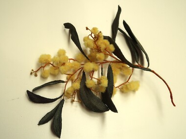 Embroiderers Guild, Victoria
Textile - 3D botanical embroidery of Acacia Pycnantha "Golden Wattle", Lynne Stone, 2025
... Australian native flora flora Botanical model of Acacia Pycnantha "Golden Wattle" in flower with open flowers, flower buds and leaves. Embroidered using machine embroidery on an organza base. Wrapped wires and hand embroidered elements, hand coloured. Textile 3D ...Lynne Stone is a Victorian based textile artist specialising in botanical embroideries of Australian native flora. Lynne has used her technical skills to develop a software program for her sewing machine to automatically stitch some elements of her designs. Botanical model of Acacia Pycnantha "Golden Wattle" in flower with open flowers, flower buds and leaves. Embroidered using machine embroidery on an organza base. Wrapped wires and hand embroidered elements, hand coloured.australian native flora, flora -
 Creswick Campus Historical Collection - University of Melbourne
Education kit - 3D Model - Leaf Structure, Biocalderoni KFT, Leaf Structure model
... 3D Model - Leaf Structure...Fagus silvatica Leaf Structure model Education kit 3D Model - Leaf Structure Biocalderoni KFT ...Plastic and foam model of the cross section of a beech leaf. Fagus silvatica -
Creswick Campus Historical Collection - University of Melbourne
Education kit - 3D Model of plant stem structure, Biocalderoni KFT, Stem cross section of plant
... 3D Model of plant stem structure...Stem cross section of plant Education kit 3D Model of plant stem structure Biocalderoni KFT ...3D cross section of microscopic view of a plant stem. -
 Vision Australia
Photograph - Image, Using a 3D map of Sydney
... model buildings on a relief map of the Sydney CBD whilst two others look on. Royal Blind Society of NSW Maps Learning layout of City of Sydney by raised map Orientation - historical RBS XI B/W photograph of blind man using relief map Using a 3D map of Sydney Photograph Image ...A blind man feels model buildings on a relief map of the Sydney CBD whilst two others look on. B/W photograph of blind man using relief mapLearning layout of City of Sydney by raised map Orientation - historical RBS XIroyal blind society of nsw, maps -
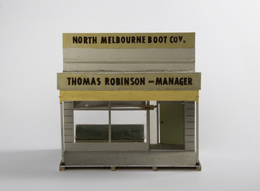 Port Fairy Historical Society Museum and Archives
Mixed media - Model, North Melbourne Boot Co, early 1970`s
... It was made by Mr Alan Mewkill a member of the Port Fairy Historical Society. This model depicts in 3D, part of the streetscape of Port Fairy in 1892 as drawn in a calendar/almanac of the time. panorama model bank street sackville street mr t robinson alan mewkill Thomas Robinson - Manager Small hand made model of a shop front form the 1892 almanac North Melbourne Boot Co. ...This model was part of a panorama 11 pieces designs from photos in an almanac printed by Port Fairy Gazette. The panorama was used by the Historical Society rooms Bank Street as a display on an extended mantel piece, before being relocated to Gipps Street. It was made by Mr Alan Mewkill a member of the Port Fairy Historical Society.This model depicts in 3D, part of the streetscape of Port Fairy in 1892 as drawn in a calendar/almanac of the time. Small hand made model of a shop front form the 1892 almanacThomas Robinson - Managerpanorama, model, bank street, sackville street, mr t robinson, alan mewkill -
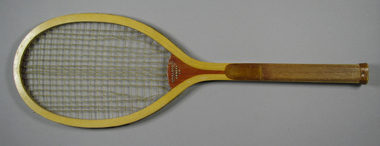 Tennis Australia
Racquet, Circa 1923
... A Spalding 'Geneva 3D' tennis racquet, featuring: solid convex throat; and, fine-grooved, octagonal handle. 'A.G. Spalding & Bros. Made in U.S.A.' logo encircling ball trademark features on throat on reverse. Decal of model...Tennis Australia Melbourne Park Olympic Boulevard Melbourne Park Melbourne melbourne Tennis A Spalding 'Geneva 3D' tennis racquet, featuring: solid convex throat; and, fine-grooved, octagonal handle. 'A.G. Spalding & Bros. Made in U.S.A.' logo encircling ball trademark features on throat on reverse. Decal of model ...A Spalding 'Geneva 3D' tennis racquet, featuring: solid convex throat; and, fine-grooved, octagonal handle. 'A.G. Spalding & Bros. Made in U.S.A.' logo encircling ball trademark features on throat on reverse. Decal of model name features across throat on obverse. Materials: Wood, Lacquer, Glue, Metal, Ink, Gut, Leather, Paint, Stringtennis -
Moorabbin Air Museum
Manual (Item) - Martin Mariner structural repairs, Mariner (Models PBM-3S & PBM-3D) Airplane Hand Book of Structural Repair
... Moorabbin Air Museum Moorabbin Airport 12 First Street Moorabbin melbourne RAAF Mariner (Models PBM-3S & PBM-3D) Airplane Hand Book of Structural Repair Manual Martin Mariner structural repairs ...RAAF