Showing 27 items matching "adjustable rod"
-
 Kiewa Valley Historical Society
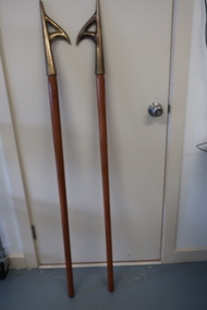
Pike Poles
... ...adjustable rod...Used by AGL employees in the Bogong Power Station (Kiewa hydro Electric Scheme) to remove plaster and wood wall cladding during a fire. Curtain rod adjustable rod Long (1390 mm) polished wooden rods that taper from a circumference of 100 mm to 115 mm at the fitted bronze end. ...Wooden rods known as Pike Poles, a tool used in a fire situation to remove plaster and wood wall cladding. Used in power stations, houses and other buildings.Still available but with a fibreglass handle.Used by AGL employees in the Bogong Power Station (Kiewa hydro Electric Scheme) to remove plaster and wood wall cladding during a fire.Long (1390 mm) polished wooden rods that taper from a circumference of 100 mm to 115 mm at the fitted bronze end. The bronze hooks are shaped like a capital R with an extended back to the R. The hooks are called "Pike Poles".curtain rod, adjustable rod -
 Tatura Irrigation & Wartime Camps Museum
Saw, Bow, 1940's
... Handmade bow saw, wooden frame, metal serrated blade, adjustable metal rod joining frame top...Tatura Irrigation & Wartime Camps Museum 49 Hogan Street Tatura the-murray Made by internees at Camp 3, Tatura and used there as a hand carpentry tool. saw tools tc camp 3 tatura ww2 camp 3 trades Handmade bow saw, wooden frame, metal serrated blade, adjustable metal rod joining frame top Saw, Bow ...Made by internees at Camp 3, Tatura and used there as a hand carpentry tool.Handmade bow saw, wooden frame, metal serrated blade, adjustable metal rod joining frame topsaw, tools, tc, camp 3, tatura, ww2 camp 3, trades -
Tatura Irrigation & Wartime Camps Museum
Fret Saw, 1940
... Handmade wooden saw varnished frame, turned handles ( either end)with supportin centre struts & metal serrated cutting blade with adjustable metal rod....Tatura Irrigation & Wartime Camps Museum 49 Hogan Street Tatura the-murray Made by internee at camp 3 tatura, used as a handtool. blade made from steel,(stays from a ladies corset) tatura RH ( on adhewsive tape) Handmade wooden saw varnished frame, turned handles ( either end)with supportin centre struts & metal serrated cutting blade with adjustable metal rod. Fret Saw ...Made by internee at camp 3 tatura, used as a handtool. blade made from steel,(stays from a ladies corset)Handmade wooden saw varnished frame, turned handles ( either end)with supportin centre struts & metal serrated cutting blade with adjustable metal rod.RH ( on adhewsive tape)tatura -
 Dunkeld Museum Inc.
Carbon Arc Lamp, Carbon Arc Lamp out of a Film Projector
... These rods allow adjustment and totation of the carbon rods which hold the arc. ...These rods allow adjustment and totation of the carbon rods which hold the arc. ...This lamp was the light source for the projector which was operated at Dunkeld and the wider district during the 1920's and 30's. The company which operated it was called Royal Pictures and showede their films in district halls. Owned by Claude Taylor and Reuben Schache. The projector was hand operated. Films were also shown outside on a large screen outside the Royal Mail Hotel.Metal carbon arc lamp. 6 Adjustor screws to adjust the rods to strike and hold the carbon arc. These rods allow adjustment and totation of the carbon rods which hold the arc. Brass feferrules are used for fine adjustments. Hand wheels are insulated to protect the operator. This arc lamp produced the light for a movie projector.None visibleentertainment, films, carbon lamp -
Tatura Irrigation & Wartime Camps Museum
Bow Saw, 1940
... Bow Saw, Handmade, Wooden Frame , Varnished & Polished, turned shaped handles either end, centre strut across frame, metal serrated edged blade & adjustable metal rod at top of frame....Bow Saw, Handmade, Wooden Frame , Varnished & Polished, turned shaped handles either end, centre strut across frame, metal serrated edged blade & adjustable metal rod at top of frame. Bow Saw ...Made by internee in Camp 3 TaturaBow Saw, Handmade, Wooden Frame , Varnished & Polished, turned shaped handles either end, centre strut across frame, metal serrated edged blade & adjustable metal rod at top of frame.R.H.tatura, ww2, trades, tools -
 Kilmore Historical Society
Tool - Shoe stretcher, Metal shoe stretcher
... Metal toe shape with 6 holes in top, cut out at point of toe.Toe and heel joined by adjustable metal rods. Metal heel extender with holes on sides to put metal rod into so as to adjust length....Kilmore Historical Society 4 Powlett Street Kilmore daylesford-and-the-macedon-ranges Sky-line Made in England stamped under heel extender Metal toe shape with 6 holes in top, cut out at point of toe.Toe and heel joined by adjustable metal rods. Metal heel extender with holes on sides to put metal rod into so as to adjust length. ...Metal toe shape with 6 holes in top, cut out at point of toe.Toe and heel joined by adjustable metal rods. Metal heel extender with holes on sides to put metal rod into so as to adjust length.Sky-line Made in England stamped under heel extender -
Tatura Irrigation & Wartime Camps Museum
Bow Saw, 1940's
... Metal serrated edged blade made from gramophone spring. Adjustable metal rod at top of frame...Metal serrated edged blade made from gramophone spring. Adjustable metal rod at top of frame Bow Saw ...Used by internees at Camp 3Bow-saw handmade. Wooden frame, turned and shaped handles either end. Centre wooden strut across frame. Metal serrated edged blade made from gramophone spring. Adjustable metal rod at top of framesaw - bow, camp 3, tatura, ww2, trades, tools -
 Bendigo Military Museum
Equipment - AEOROPLANE LAMP, c.WWII
... Adjustable lamp, metal square rod stand with black paint, metal bracket (rusted), white electrical cord, small clear globe (missing remainder of stand), bakelite electrical socket, metal light shade, grey paint....Refer Cat No 1959 for his service history. lighting-electric military history - air force Adjustable lamp, metal square rod stand with black paint, metal bracket (rusted), white electrical cord, small clear globe (missing remainder of stand), bakelite electrical socket, metal light shade, grey paint. ...Navigators Light from a Wellington Bomber. Item belonged to Maxwell Lennox Matheson No 418447 RAAF. Refer Cat No 1959 for his service history. Adjustable lamp, metal square rod stand with black paint, metal bracket (rusted), white electrical cord, small clear globe (missing remainder of stand), bakelite electrical socket, metal light shade, grey paint.lighting-electric, military history - air force -
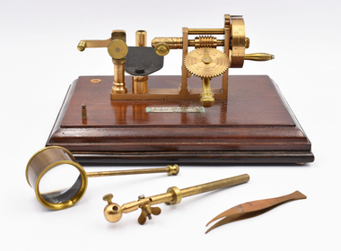 National Wool Museum
Functional object - Yarn Spinner and Accessories, John Nesbitt, 19th Century
... Brass rod with hinge and wingnut, and ball at end. Ball at end has an adjustment mechanism. ...Brass rod with hinge and wingnut, and ball at end. Ball at end has an adjustment mechanism. ...Nino Corda was a Geelong based textile designer who worked at various textile mills between 1957 & 2003. He travelled the world in search of the latest fashions and techniques and developed timeless designs that were much loved by Australians. These items are on rotational display at the National Wool Museum’s ‘In the Factory’ exhibition. For many years, Nino also worked as part of the Honorary Staff of the National Wool Museum. His passion for the world of textiles provided energy and knowledge to the visitors and staff of the museum. Although Nino has now retired from his honorary position and has hung up his Australian Tartan vest, these items will continue to serve the community in sharing the stories of Australian Textile design.Custom made wooden hinged box with a hook latch. Brass yarn spinner, attached to a mahogany wood plinth base, which spins fibre into cord/yarn/thread. It has dials to set the rate that it spins. Metal plaque with black inlaid enamel lettering. Small cork inlay. Brass rod with hinge and wingnut, and ball at end. Ball at end has an adjustment mechanism. Rod also has an adjustable circular collar. Pair of curved tweezers. Circular magnifying glass on long thin handle. Glass has two concave lenses. Weaving sample in shades of blue, green and brown. Twill weave. Alternate pattern samples separated by red thread.Brass plaque on base of spinner: 42 MARKET St / John Nesbitt / REGd TRADE MARK / LIMd / MANCHESTER Underside of wooden plinth: 4976apparatus, textile, testing, spinning, nino corda, magnifyer, tools, brass, mahogany, tweezers, yarn, spinner, design, john nesbitt, manchester, england, 19th century, engineering, manufacturing -
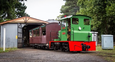 Puffing Billy Railway
NRT1, Ruston & Hornsby Diesel Locomotive, 1951
... This type of locomotive was popular in many industrial locations, with their unique clutch-less 3 speed gearbox meaning the driver could control them whilst walking alongside, a bonus when shunting. Adjustable tie rods meant that as the axles moved on the springs, they followed the radius of the drive chains, reducing the chances of chain snatch LOCOMOTIVE DETAILS NRT class No. originally constructed : No. in service : 1 No. stored: Wheel arrangement : 0-4-0DM Roadworthy weight : 9T 3cwt. ...This type of locomotive was popular in many industrial locations, with their unique clutch-less 3 speed gearbox meaning the driver could control them whilst walking alongside, a bonus when shunting. Adjustable tie rods meant that as the axles moved on the springs, they followed the radius of the drive chains, reducing the chances of chain snatch LOCOMOTIVE DETAILS NRT class No. originally constructed : No. in service : 1 No. stored: Wheel arrangement : 0-4-0DM Roadworthy weight : 9T 3cwt. ...NRT1 - Ruston & Hornsby Diesel Locomotive Built in 1951 to a gauge of 3', this Ruston diesel locomotive or rail tractor operated on the State Electricity Commission of Victoria’s Kiewa scheme. Some years later, it was regauged to 2'6" and was operated by the Melbourne & Metropolitan Board of Works. NRT1 is a Ruston & Hornsby diesel locomotive, built in England in 1951 to a gauge of 3 feet, and was initially employed by the State Electricity Commission of Victoria. It was later re-gauged to 2' 6" and ended it's working life in 1977 when it was transferred to Puffing Billy. In 1977, it was taken to the P.B.P.S. Steam Museum and stored until 1978 when it was taken to the Emerald Carriage Workshops. Later in 1983 it was returned to service as NRT1 following the V.R. classification procedure as a narrow-gauge rail tractor, but it had number plates installed and was painted Hawthorn green. It will eventually be painted the red of V.R. rail tractors with the number & class painted on in black. This type of locomotive was popular in many industrial locations, with their unique clutch-less 3 speed gearbox meaning the driver could control them whilst walking alongside, a bonus when shunting. Adjustable tie rods meant that as the axles moved on the springs, they followed the radius of the drive chains, reducing the chances of chain snatch LOCOMOTIVE DETAILS NRT class No. originally constructed : No. in service : 1 No. stored: Wheel arrangement : 0-4-0DM Roadworthy weight : 9T 3cwt. Maximum axle load : 4T 15cwt. Tractive effort (85%) : Length overall: 15' 6" Height overall: 10' Driving wheel diameter: 18" Date of manufacture: 1950 Manufacturer : Ruston Hornsby Place of manufacture: Lincoln, England Locomotive type : Diesel Mechanical Manufacturers classification : 48 DL Historic - Industrial narrow Gauge Railway - Ruston & Hornsby diesel locomotive used by State Electricity Commission of Victoria - NRT1 - Ruston & Hornsby Diesel Locomotive NRT1 - Ruston & Hornsby Diesel Locomotive made of steel NRT1 ruston & hornsby diesel locomotive, nrt1 diesel locomotive, nrt1, puffing billy -
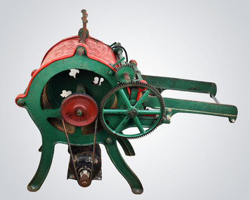 National Wool Museum
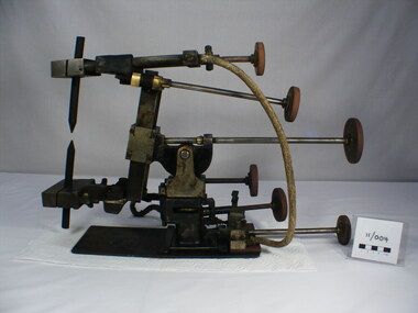
Picker
... A power cable extends from the motor and there are two adjustable metal rods on the top of the machine, the purpose of these rods is presently unknown. ...A power cable extends from the motor and there are two adjustable metal rods on the top of the machine, the purpose of these rods is presently unknown. ...Wool picking machine designed to separate locks of wool before it is carded and spun. The picker opens the wool’s locks which makes it easier to send the fleece through a carding machine. It does this by teasing the fibres (which can also be done by hand just by pulling the lock structure apart), but a picker does this in bulk and much quicker than what can be done by hand. It is possible to spin fibres directly after the picking stage; however, it is usually more desirable to card and blend them with other fibres. Typically, at a textile mill, a picking machine can separate enough lengths of fibre for a full day’s work after just a single hour. It will also help to remove any vegetation matter or other any unwanted elements that may be present in the wool. The quality of the casting on this machine suggest that it was made locally, either in Australia or New Zealand. Mike Leggett, the donor of the machine, acquired it from New Zealand where the seller said it had been used by his father to pick wool to make hand stuffed horse saddles. Mike attempted to used it a couple of times to pick alpaca hair, but the speed of the attached motor caused damage to the fibres. The motor is thought to be an added attachment, sometime around the 1960s judging by its age, while the machine itself is thought to be dated around the 1920s. The machine works by inserting wool through the rollers. Initially there was a conveyor belt feeder system which was powered by the handle on the side. This conveyor belt has been removed however, most likely due to age and deterioration. Wool is now fed through the initial teeth and is met by a spiked rotating drum which works to separate the fibres. The separated fibres would then complete a loop of the drum before being dispatched somewhere below, around where the motor presently sits, at a rapid rate of speed. Typically this wool will be collected in a closet or large catchment area, as can be seen from the 8:47 minute marker in the linked video (link - https://www.youtube.com/watch?v=kMjx-t3tH3A). It is not apparent how the wool is collected with this machine. Red and green machine with four green legs currently attached to a wooden pallet with wheels for easy movement. The green legs lead up to a red central circular barrel from which many attachments are present. Also present on the wooden pallet is a small black motor which is attached by a rubber belt to the central drum inside the red barrel. The belt spins the wooden drum via a dark red circular plate attached to the side of the drum. On the other side of the red barrel, a green handle extends for turning the picker’s conveyor belt feeder system. Two green walls extend forward from the central red barrel, guarding either side of where the conveyor belt would have been. At the start of these walls is a wooden cylinder, which the conveyor belt would have wrapped around, followed by two interlocking gears which rotate and accept the fed wool. The red roof extends over the central cylinder from here, securing the wool inside and protecting hands from the heavily spiked internal wooden cylinder which rotates and separates (picks) the wool. Extending over the top of this red roof is a green handle which reaches to the back of the machine (not pictured). Here it accepts a weight to ensure pressure is always present for the initial feeder interlocked gear teeth. There are two large gear cogs on the rubber belt side of the machine and 3 small gear cogs on the handle side of the machine, all coloured green. A green handle is also present at the rear of the machine, below the location from which the weight is hanging. A power cable extends from the motor and there are two adjustable metal rods on the top of the machine, the purpose of these rods is presently unknown. Black texter. On top of drum. Wording: HG3707 Wording. Imprint: BRACEWIND BLYN On motor. Wording AEIwool picking, textile manufacturing, wool processing -
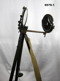 Bendigo Military Museum
Instrument - Duplex Heliograph Mk V - 1940 with Tripod, LUCO Art Metal Coy Ltd, London, 1940
... Keeping their head still, they then adjusted the aiming rod so its cross wires bisected the target, they then turned up the sighting vane, which covered the cross wires with a diagram of a cross, and aligned the mirror with the tangent and elevation screws, so the small shadow that was a reflection of the unsilvered spot hole was on the cross target. ...Keeping their head still, they then adjusted the aiming rod so its cross wires bisected the target, they then turned up the sighting vane, which covered the cross wires with a diagram of a cross, and aligned the mirror with the tangent and elevation screws, so the small shadow that was a reflection of the unsilvered spot hole was on the cross target. ...The Heliograph MkV is a fascinating piece of historical surveying and communications equipment. It was primarily used for visual signaling by reflecting sunlight with a mirror to send coded messages over long distances. This method was primarily useful in remote areas where other forms of communication were not available. The MkV model, specifically, was widely used by the British Army and other military forces from around 1906 until the mid 1960s. It remained in use with the Australian Army Survey Corps until the mid 1980s. The device typically included a 5 - inch mirror and was often mounted on a tripod for stability. Initially the instrument was used to communicate between survey stations using Morse code to coordinate their activities. Later when better forms of communication were available, they were used for precise angle alignment where the sunlight reflection from the mirror was targeted between the survey stations to give very accurate results. The MkV was relatively light weight and portable, making it ideal for use in the field. It could be setup and adjusted quickly. The heliograph had an adjustable mirror that could be tilted to reflect sunlight towards a distant receiver. Surveyors could align the mirror using a sighting device. Whilst it was primarily used by the Military it was also used in civil surveying particularly in the remote areas of Australia. The British Army Mark V version uses a flat round mirror with a small unsilvered spot in the centre. The sender aligned the heliograph to the target by looking at the reflected target in the mirror and moving their head until the target was hidden by the unsilvered spot. Keeping their head still, they then adjusted the aiming rod so its cross wires bisected the target, they then turned up the sighting vane, which covered the cross wires with a diagram of a cross, and aligned the mirror with the tangent and elevation screws, so the small shadow that was a reflection of the unsilvered spot hole was on the cross target. This indicated that the sunbeam was pointing at the target. If the sun was in front of the sender, its rays were reflected directly from this mirror to the receiving station. If the sun was behind the sender, the sighting rod was replaced by a second mirror, to capture the sunlight and direct it onto the main mirror to reflect it to the receiving station.. 1 Brish Army "Mance" Mk V A253 Heliograph has two 125mm diameter mirrors on a brass arm with targeting attachments. The Instrument is mounted on a three-legged tripod of brass and mahogany with spiked feet, approximately 1.2 metres high. The instrument was made by LUCO Art Metal Co Ltd, London in 1940. .2 A military green metal carrying safety storage case with khaki shoulder strap.A253 stamped on instrumentroyal australian survey corps, rasvy, fortuna, army survey regiment, army svy regt, asr -
Kiewa Valley Historical Society
Projector - 'Pictoral' Bogong State School, 1925 - 1935
... adjust the height within a cm. The back is a tall irregular box shape with ventilation on 2 sides of the bottom and at the top. There is a brass plaque attached above 1 vent and an electric cord, with switch, below it. Attached at each side of the front of this box is a cylinder fitted horizontally facing the front where the lense is fitted. At right angles above there is another cylinder, hollow, with a rod...adjust the height within a cm. The back is a tall irregular box shape with ventilation on 2 sides of the bottom and at the top. There is a brass plaque attached above 1 vent and an electric cord, with switch, below it. Attached at each side of the front of this box is a cylinder fitted horizontally facing the front where the lense is fitted. At right angles above there is another cylinder, hollow, with a rod ...As Bogong State School was located in a remote area especially in winter when the weather and therefore the road isolated the school for an indefinite time, the school was provided with up to date equipment with a comprehensive library and educational films that wouldn't disadvantage the students. Educational films covered all subjects and areas of the curriculum. The projector was very modern at the time. The Society for Visual Education Inc was founded in 1919 as a for-profit educational publisher dedicated to the use of new technologies in teaching.This projector was used at the Bogong State School which opened in 1941 for the children of the employees of the State Electricity Commission of Victoria who were working on the Kiewa Hydro Electric Scheme. The school was outstanding as reported by the school inspectors regarding the education of the pupils which was also supported by new and modern equipment. The nearest school was 14 km away over a dirt road that wound around the Victorian mountains and often closed due to bad weather. Bakelite box holding a globe and a small black tin projector on brown rectangular bakelite base with 4 round rubber stands at each corner. It is able to be moved upwards from the front to adjust the height within a cm. The back is a tall irregular box shape with ventilation on 2 sides of the bottom and at the top. There is a brass plaque attached above 1 vent and an electric cord, with switch, below it. Attached at each side of the front of this box is a cylinder fitted horizontally facing the front where the lense is fitted. At right angles above there is another cylinder, hollow, with a rod for the film to be placed. Globe also in Bakelite boxPlaque: Pictorial Projector / Model Q / 120 Volts. 100 Watts / No. 23736 / Manufactured / Society of Visual Education Inc. / Chicago U.S.Aprojector, bogong primary school, education, educational films, visual education, kiewa hydro electric scheme -
 Kiewa Valley Historical Society
Backpack
... There are webbed shoulder straps on an angle attached to the back with adjustable straps. There is a thin metal rod on the outside of each side presumably to enable items to be hung from them. ...There are webbed shoulder straps on an angle attached to the back with adjustable straps. There is a thin metal rod on the outside of each side presumably to enable items to be hung from them. ...This pack is made from materials available at the time and was used to carry supplies and equipment for bushwalking and/or cross country skiing. It is designed to protect the contents in all weather and to be as comfortable and practical as possible. The Bogong High Plains was a popular destination for bushwalking and cross country skiing. This backpack is an early example of the equipment used for extended walks and/or cross country skiing. Heavy green canvas back pack with flap at top to cover contents and to attach at base. Sides fold over at the top. The back is attached with zig zag cord with 5 holes down each side. The front piece has 2 pockets with straps to secure them. The sides have a wooden rectangular piece wrapped by canvas to maintain the shape of the pack. There are webbed shoulder straps on an angle attached to the back with adjustable straps. There is a thin metal rod on the outside of each side presumably to enable items to be hung from them. On the inside of the flap: Leon Henry/Trendweth(?)/ West Brunswick/Melbourne/ Victoria/ Australia Previous name and address has been crossed out.backpack; bogong high plains; bushwalking; cross country skiing -
 Kiewa Valley Historical Society
Backpack
... rods. There are 2 strips of wide canvas at the back. These are held by an adjustable white cord to increase comfort and for a better fit....rods. There are 2 strips of wide canvas at the back. These are held by an adjustable white cord to increase comfort and for a better fit. ...This pack is made from materials available at the time and was used to carry supplies and equipment for bushwalking and/or cross country skiing. It is designed to protect the contents in all weather and to be as comfortable and practical as possible.The Bogong High Plains was a popular destination for bushwalking and cross country skiing. This backpack is an example of the equipment used for extended walks and/or cross country skiing.Orange nylon backpack with long flap at the top. This flap has a pocket inserted at the end and 2 holes at each side to tie the rope to the base of the pack. It has 5 zippered pockets each with a flap - 2 on each side top and bottom and 1 large one across the back. The frame is aluminium with a rod each side and 3 slightly curved rods joined to them horizontally and 2 curved thin vertical rods. There are 2 strips of wide canvas at the back. These are held by an adjustable white cord to increase comfort and for a better fit.backpack; bogong high plains; bushwalking; cross country skiing; -
 Kiewa Valley Historical Society
Backpack
... adjusting the shape of the pack. It has 6 pockets with zips - 2 each side and 2 across the back. There is 1 pocket with a velcro fastening on the outside of the flap. The cord enables the closing of the top. The frame is aluminium with 2 nearly straight sides and continuing across the top. There are 3 separate aluminium rods...adjusting the shape of the pack. It has 6 pockets with zips - 2 each side and 2 across the back. There is 1 pocket with a velcro fastening on the outside of the flap. The cord enables the closing of the top. The frame is aluminium with 2 nearly straight sides and continuing across the top. There are 3 separate aluminium rods ...This pack is made from materials available at the time and was used to carry supplies & equipment for bushwalking and/or skiing. it is designed to protect the contents in all weather and to be as comfortable and practical as possible.The Bogong High Plains was a popular destination for bushwalking and cross country skiing. This backpack is an example of the equipment used for extended walks and/or cross country skiing.Orange backpack with nylon front and canvas back. The back flap has cord threaded along the sides for adjusting the shape of the pack. It has 6 pockets with zips - 2 each side and 2 across the back. There is 1 pocket with a velcro fastening on the outside of the flap. The cord enables the closing of the top. The frame is aluminium with 2 nearly straight sides and continuing across the top. There are 3 separate aluminium rods that are joined across and 1 piece of canvas.backpack; bush walking; bogong high plains; cross country skiing -
 Bendigo Military Museum
Equipment - TRAINING STAND FOR .303 IN LEE ENFIELD RIFLE, 21 Bn. AIF, c1915-1918
... adjustable 'arm' . At the end of each arm is a leather covered 'U' section. Under the arm is a large threaded rod and knurled knob, this is to adjust elevation. ...adjustable 'arm' . At the end of each arm is a leather covered 'U' section. Under the arm is a large threaded rod and knurled knob, this is to adjust elevation. ...This is a WW1 stand for mounting a .303 rifle, to train soldiers in shooting.This device consists of two parts; 1. Top part has an adjustable 'arm' . At the end of each arm is a leather covered 'U' section. Under the arm is a large threaded rod and knurled knob, this is to adjust elevation. At the center of the arm is a pivot that can lock into position. This top section is mounted on a tripod, it can be removed. 2. This is a steel tripod made out of 'T' section steel. There are fixed cross braces about 40 cm fom bottom. The top has a tube section within which the upper arm mounts.Marked on one leg is "XXI". Believed to be from 21st Bn. AIF. on the top of that leg is a very small arrow head.ww1, training, .303 rifles -
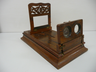
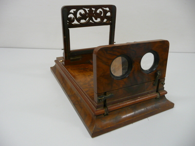 Bendigo Historical Society Inc.
Leisure object - TABLE TOP STEREOSCOPE VIEWER, 1870's
... Wooden stereoscope viewer made for table top viewing with adjustable positions for ease of viewing and focusing, with a large loose magnifying glasss which can be attached to 2 folding brass rods.Outer casing covered in a rosewood veneer,brass catches, hinges & rods, bone screw on knobs, purple felt on base....History House 11 Mackenzie Street Bendigo goldfields PHOTOGRAPHY Viewers stereoscope Wooden stereoscope viewer made for table top viewing with adjustable positions for ease of viewing and focusing, with a large loose magnifying glasss which can be attached to 2 folding brass rods.Outer casing covered in a rosewood veneer,brass catches, hinges & rods, bone screw on knobs, purple felt on base. ...Wooden stereoscope viewer made for table top viewing with adjustable positions for ease of viewing and focusing, with a large loose magnifying glasss which can be attached to 2 folding brass rods.Outer casing covered in a rosewood veneer,brass catches, hinges & rods, bone screw on knobs, purple felt on base.photography, viewers, stereoscope -
 Bendigo Historical Society Inc.
Leisure object - TABLE TOP STEREOSCOPE VIEWER, 1870's
... Wooden Stereoscope Viewer made for tabletop viewing with adjustable positions for ease of viewing and focusing, outer casing covered in a rosewood veneer, brass catches, hinges & rods, green hessian on base....History House 11 Mackenzie Street Bendigo goldfields PHOTOGRAPHY Viewers stereoscope Wooden Stereoscope Viewer made for tabletop viewing with adjustable positions for ease of viewing and focusing, outer casing covered in a rosewood veneer, brass catches, hinges & rods, green hessian on base. ...Wooden Stereoscope Viewer made for tabletop viewing with adjustable positions for ease of viewing and focusing, outer casing covered in a rosewood veneer, brass catches, hinges & rods, green hessian on base.photography, viewers, stereoscope -
 Bay Steamers Maritime Museum
model steam engine
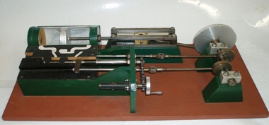
... rod which is connected to an eccentric clamped to the crankshaft and is the nearer to the flywheel of two eccentrics. This eccentric is attached to the crankshaft at an angle of 90 degrees to the crank-pin attached to the flywheel. To operate the model simply turn the flywheel by means of the handle attached to its crank-pin. A second eccentric is also attached to the crankshaft, further away from the first eccentric, and it is adjusted...rod which is connected to an eccentric clamped to the crankshaft and is the nearer to the flywheel of two eccentrics. This eccentric is attached to the crankshaft at an angle of 90 degrees to the crank-pin attached to the flywheel. To operate the model simply turn the flywheel by means of the handle attached to its crank-pin. A second eccentric is also attached to the crankshaft, further away from the first eccentric, and it is adjusted ...This model was found in the collection of Bay Steamers Maritime Museum. It is not knowt who created it but it is supposed that it was constructed to educate the many masters of the Wattle in the operation of a steam engine - a not so common mode of power these days. A Bay Steamers Maritime Museum examined the model in March 2012 and discovered that is was in poor repair. Using his existing knowledge, and with reference to some historic texts, he made some repairs and returned the model to working order. Here is his anaylsis of the situation as an excerpt from the Bay Steamers Maritime Museum newsletter Steamlines May 2012 "I was confronted with a model of a steam engine used years ago as a training aid for hopeful steam engineers. Already having a knowledge of steam operations, I considered a museum write-up for that model a ‘piece of cake’. However, on turning the model’s crankshaft, the valve timing seemed ‘out of kilter’ with the movement of the piston. Problem was that the two eccentrics on the crankshaft were not properly secured to it. Eventually I fastened the two eccentrics to the crankshaft where I felt that they should be and then realized that one of them had a chain-driven valve-timing device attached. This would be adjusted while an engine was running to achieve best performance and fuel economy whilst in operation by accurately controlling the period of time during which steam under pressure from the boiler would be admitted to the cylinder and give greater time for the steam to expand in the cylinder, move the piston and turn the crankshaft and thus, drive the attached apparatus. When the valves were correctly set up it was then possible to get the model to function properly.The model comprises a green section, which is the actual the model mounted on a brown painted board. There are two parts of the model, painted white representing the steam passages, and black representing the cast- iron portions of the cylinder-block casting, and of the main valve sliding between the cylinder a second sliding valve. Of the black portions, one slides back and forth being connected to a rod which is connected to an eccentric clamped to the crankshaft and is the nearer to the flywheel of two eccentrics. This eccentric is attached to the crankshaft at an angle of 90 degrees to the crank-pin attached to the flywheel. To operate the model simply turn the flywheel by means of the handle attached to its crank-pin. A second eccentric is also attached to the crankshaft, further away from the first eccentric, and it is adjusted to operate 90 degrees from the first eccentric (that is, 180 degrees from the crank-pin) A piston (painted silver) is located in a plastic cylinder and has a piston rod which passes through one end of the cylinder, (in actual practice a steam-proof gland seals the cylinder against loss of steam) terminating in a cross-head slide between four rails guiding it. From this cross-head, a connecting rod joins the piston-rod to the flywheel via the crank-pin attached to the flywheel which is part of the crankshaft. (In actual practice, a flywheel may not be used, particularly in a multi-cylinder engine.) The white portions of the model painted nearest to the cylinder represent the two steam ports cast into the main cylinder block, whilst one section painted in between those two represents the exhaust outlet (which may be connected to a condenser to conserve water, or to the open air). The main slide valve has three white-painted portions painted thereon. It has two white-painted marks representing the steam passages to the steam ports into the cylinder, and a third section in between the other two, being that part of the valve through which exhaust steam passes in line with the ports in the cylinder block. By rotating the flywheel, the operations of an engine will be observed as steam is admitted to the main valve via the gap between the two jaws of two moveable portions of a second sliding valve which is operated by the second eccentric attached to the crank-shaft. This eccentric is used to finely tune the valve timing of this model to obtain best running results of an engine. There are various methods used for reversing a steam engine. model compound steam engine, steam engine, model, crankshaft, valve, flywheel, wattle, engineer, eccentrics -
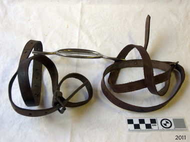 Flagstaff Hill Maritime Museum and Village
Equipment - Bridle Bit and Headstall, Early 1900s
... Bridle bit and headstall; horizontal metal oval shaped bit with a narrow rod each end that finishes in a narrow loop. Adjustable leather straps with holes are threaded through the narrow metal loops....Flagstaff Hill Flagstaff Hill Maritime Museum and Village Warrnambool Maritime Museum Maritime Village Great Ocean Road Shipwreck Coast horse husbandry horse equipment horse riding 1900 Melbourne headstall bridle horse headgear riding gear horsemanship equestrian equipment headgear Bridle bit and headstall; horizontal metal oval shaped bit with a narrow rod each end that finishes in a narrow loop. Adjustable leather straps with holes are threaded through the narrow metal loops. ...The leather headstall is connected to the metal bit are used in conjunction with a set of leather reins to guide and steer a horse or other similar animal. Made in Melbourne in 1900.The horse bridle and headstall were used in Warrnambool in the early 20th century. Bridle bit and headstall; horizontal metal oval shaped bit with a narrow rod each end that finishes in a narrow loop. Adjustable leather straps with holes are threaded through the narrow metal loops.flagstaff hill, flagstaff hill maritime museum and village, warrnambool, maritime museum, maritime village, great ocean road, shipwreck coast, horse husbandry, horse equipment, horse riding, 1900, melbourne, headstall, bridle, horse headgear, riding gear, horsemanship, equestrian equipment, headgear -
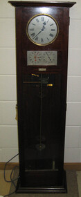 Federation University Historical Collection
Object, Synchronome Co. Ltd, Synchronome Frequency Checking Master Clock No. 2191, c1930
... rod, below suspension spring: Serial number (?) 0000005 Rectifier in bottom cabinet: >"Hilco Rectifier" >"A.C. Volts 230/240" >"Model 1060/S" >"A.C. Amperes" >"Serial No. 1060/S >"Phases 1" >"D.C. Volts 6" >"C.P.S. 50" >"D.C. Amperes 1" >"Made in Australia by Hilco Transformers McIntyre St., Burwood, Victoria." Bakelite electrical plug: makers mark Lower cabinet, RH side panel, pressed tin plate: "AC" (upside down) Brass speed adjustment...rod, below suspension spring: Serial number (?) 0000005 Rectifier in bottom cabinet: >"Hilco Rectifier" >"A.C. Volts 230/240" >"Model 1060/S" >"A.C. Amperes" >"Serial No. 1060/S >"Phases 1" >"D.C. Volts 6" >"C.P.S. 50" >"D.C. Amperes 1" >"Made in Australia by Hilco Transformers McIntyre St., Burwood, Victoria." Bakelite electrical plug: makers mark Lower cabinet, RH side panel, pressed tin plate: "AC" (upside down) Brass speed adjustment ...Information from Norman F. Dalton: Ballarat had a reticulated DC supply in the early part of last century and in 1905 had sufficient generating capacity to enable the trams to be changed from horse drawn to DC electricity. The use of electricity increased with the main power station located on Wendouree Parade, near Webster Street, under the ownership of The Electric Supply Company of Victoria. AC generating plant was installed in 1925 and conversion to AC proceeded. In 1934 the company was taken over by the State Electricity Commission Victoria (SECV) and more AC generation was installed and the changeover of customers was accelerated. This is around the time that the Synchronome Frequency Checking Mast Clock was installed at the Wendouree Parade Power Station. The SECV Annual Report of 1921 states: ::Section 11 of the act directed the COmmission to enquire into the question of securing the adoption of such standards of plant and equipment of a system, frequency and pressure for the generation and distribution of electricity as will admit of the efficient interconnection of undertakings throughout the State. In 1934 when the SECV took over the Ballarat operations the question of linking with the State grid had been a planned operation for some years but due to financial considerations had hindered it and in fact would continue to do so for a further 10 years. So while the need for close frequency control for interconnection was hardly an issue, the need to keep electric clocks correct was important, particularly as this item was a frequent sales point to cover the inconvenience and sometimes expense of converting from DC to AC. The clock is a very accurate pendulum clock with provision for varying effective length during operation for precise time regulation. There are two normal time dials and one is controlled by the pendulum and the other is operated by the system frequency. When the clock was in use it was installed by the MEter and Tests Laboratory and the time was checked daily by radio time signals. The two dials were repeated in the operators control panel in the Power Station. A maximum deviation between the two dials was set in the operating instructions (eg 5 seconds) and the operator would correct this when necessary by remote manual alteration of the turbine governor set point. The clock was used to drive and regulate a system of "slave" clocks which were used to display the time in various locations around the power station. A slave clock is a simple clock which is driven by a small electric motor, its accuracy is regulated by the master clock every 30 seconds to ensure that it and all the other slave clocks in the station are on exactly the right time; slave clocks were placed in various locations, from common rooms to workshops. A master clock could potentially run thousands of slave clocks at one plant. The clock also contains a rectifier. A rectifier is a device that is used to convert AC power to more stable DC current.Two clocks in a timber case. Both are electric, one is powered by the main pendulum mechanism, the other is a self contained electric clock. The main mechanism is of the gravity arm and roller type, which sends an impulse to the slave clocks every 30 seconds. The This Synchronome Frequency Checking Master Clock was used at the Ballarat Power Station. Below the main section of the case is a smaller cabinet containing a rectifier to provide consistent DC power for the clock. The rectifier was made by the Victorian company Hilco, which was located in Burwood. There is a high chance this is not the original rectifier from this clock as there appears to be brackets to hold a larger device in the space the rectifier occupies.Front below main clock face on front of case: "Patented Sychronome Brisbane" Lower left-hand clock face: "Frequency time" Lower right-hand clock face: "Standard Seconds" Synchronous electric clock mechanism on door (Frequency time clock): >200/250 V. 50~ >"Synchronomains" Made in England >Direction indicator for clock starting switch >"To start move lever in direction of arrow and release" >"Patent applied for" Mechanism for "standard seconds" clock: >"English Made" >"Patented" >Serial number "321" >0 above right-hand pillar on front-plate Mechanism for "standard seconds" clock: >"English Made" >"Patented" >Serial number "321" >0 above right-hand pillar on front-plate Mechanism for main clock face: >"English Made" >"Patented" >Serial number "8751" >0 above right-hand pillar on front-plate Inside case, back panel, top enamel plate: >Seconds Battery + Pos. > Battery Common or - Neg. >1/2 min dials Inside case, back panel, bottom enamel plate: external seconds dial Inside case, right hand side, electrical knobs: two switches, both "A.C. mains" Pendulum rod, below suspension spring: Serial number (?) 0000005 Rectifier in bottom cabinet: >"Hilco Rectifier" >"A.C. Volts 230/240" >"Model 1060/S" >"A.C. Amperes" >"Serial No. 1060/S >"Phases 1" >"D.C. Volts 6" >"C.P.S. 50" >"D.C. Amperes 1" >"Made in Australia by Hilco Transformers McIntyre St., Burwood, Victoria." Bakelite electrical plug: makers mark Lower cabinet, RH side panel, pressed tin plate: "AC" (upside down) Brass speed adjustment, outer right RH side: "S" and "F" Ivory and wood pendulum beat ruler: >Ruler, with 0 in centre and numbers 1-5 in ascending order from centre on left and right. > "Synchronome Patent." Steel plate, back panel, inside case, right hand side: >N R A" (descending) >"2191" serial number/part number Face of main clock: "Synchronome Electric" synchronome frequency checking master clock, electricity, state electricity commission, wendouree parade power station, secv, clock, time, pendulum, electric supply company of victoria, norman f. dalton, ballarat power station, rectifier, slave clock -
The Ed Muirhead Physics Museum
Microtome/W... (H.A. Waters)
... rod “A” is heated and by expansion pushes the resin block forward by a fraction. It is mounted on a long cast iron base. The movement of the block is eccentric drawing the specimen away from the knife after cutting, The glass knife ‘B’ is adjustable by means of a modified microscope column screws ‘C’. ...rod “A” is heated and by expansion pushes the resin block forward by a fraction. It is mounted on a long cast iron base. The movement of the block is eccentric drawing the specimen away from the knife after cutting, The glass knife ‘B’ is adjustable by means of a modified microscope column screws ‘C’. ...Microtome for cutting resin embedded tissues for electron microscopy. In 1957 a modified hodge microtome redesigned and built by H.A. Waters of the Melbourne University Department of Physics was acquired. The Waters microtome is of thermal expansion type - the rod “A” is heated and by expansion pushes the resin block forward by a fraction. It is mounted on a long cast iron base. The movement of the block is eccentric drawing the specimen away from the knife after cutting, The glass knife ‘B’ is adjustable by means of a modified microscope column screws ‘C’. The microtrome is driven by a continuous action electric motor mounted on the common base. Hand cutting can also be done. The cutting was controlled by viewing through a Leitz Binocular microscope mounted on the same base. The original microscope was subjected to nine modifications by Dr S Weiner from whose PhD Thesis (1962) ‘Electron Microscopical Studies of the Liver’ this information was obtained. (text provided by Professor H Attwood) Microtome made of metal and enamelled in light blue. Components are identified by the use of stick on labels. The microtome is mounted on a long cast iron rectangular base and has an electrical cord for connection to a power point.Plaque on back: “Pathology Department, University of Melbourne Serial No. 0091. Date: 7/7/1968” -
Ballarat Tramway Museum
Book, Commonwealth Industrial Gases Limited (CIG), "The Oxy-Acetylene Resurfacing of Railway Crossings", c1960
... Gives information on the resurfacing of railway crossings using oxy acetylene rods, including equipment, preparation, flame adjustment, procedures, notes, protection and material consumption. ...Gives information on the resurfacing of railway crossings using oxy acetylene rods, including equipment, preparation, flame adjustment, procedures, notes, protection and material consumption. ...Twenty four page book with light card covers, side stapled and green cloth bound titled "The Oxy-Acetylene Resurfacing of Railway Crossings". Cover green paper with darker green mottled finish. Cover and title sheet printed in black ink, the rest printed by Gestetner process using stencils with hand drawn sketches. Gives information on the resurfacing of railway crossings using oxy acetylene rods, including equipment, preparation, flame adjustment, procedures, notes, protection and material consumption. Includes an index. On inside of rear cover has printed "Issued by / Sales Department / The Commonwealth Industrial Gases Limited / Alexandra NSW" No date given for printing, possibly c1960. Company later known as CIG,On front cover in faded black ink are a number of names and a number - unreadable.trams, tramways, trackwork, railway crossing, repairs -
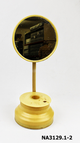 Whitehorse Historical Society Inc.
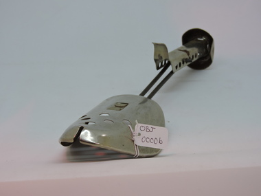
Domestic object - Shaving Companion
... It consists of an adjustable round mirror supported on a rod and standing on a round shaped bowl with a lid on top with a round hole in which a shaving brush was inserted. ...It consists of an adjustable round mirror supported on a rod and standing on a round shaped bowl with a lid on top with a round hole in which a shaving brush was inserted. ...Cream celluloid' Zylonite' shaving companion. It consists of an adjustable round mirror supported on a rod and standing on a round shaped bowl with a lid on top with a round hole in which a shaving brush was inserted. The bowl probably had a bowl insert to hold hot water.personal effects-toilet requisites, shaving -
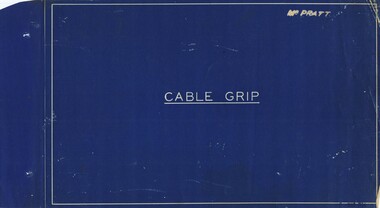 Melbourne Tram Museum
Drawing, Melbourne & Metropolitan Tramways Board (MMTB), "Cable Grip", Mar. 1934
... R3485 - General Arrangement - provides a list of the parts Index - lists all the parts and relevant drawing number R3486 - Cable Grip Lever R3487 - Cable Grip Palm Handle R3488 - Cable Grip Pawl Rod Bracket and Bolt R3493 - Pawl Box, Guard Plate and Bolt R3494 - Pawl Latch Bracket R3496 - Adjusting Screw R3498 - Cable Grip Socket R3499 - Shoe and Shoe screws R3501 - Cable Grip Link R3502 - Quadrant R3503 - Crossbar R3504 - Slide and Slide end R3505 - Cheek R3506 - Protection Piece R3510 - Top Die Holder R3511 - Back Guard R3512 - Die R3513 - Bottom Die Holder R3514 - Sole Plate R3515 - Sheave R3518 - Swinger R3519 - Swinger Frame and Setscrew R3525 - Top Guide Plate R3534 - Sheave Protector R3535 - Sheave Centre R3541 - Hornbar Washer...R3485 - General Arrangement - provides a list of the parts Index - lists all the parts and relevant drawing number R3486 - Cable Grip Lever R3487 - Cable Grip Palm Handle R3488 - Cable Grip Pawl Rod Bracket and Bolt R3493 - Pawl Box, Guard Plate and Bolt R3494 - Pawl Latch Bracket R3496 - Adjusting Screw R3498 - Cable Grip Socket R3499 - Shoe and Shoe screws R3501 - Cable Grip Link R3502 - Quadrant R3503 - Crossbar R3504 - Slide and Slide end R3505 - Cheek R3506 - Protection Piece R3510 - Top Die Holder R3511 - Back Guard R3512 - Die R3513 - Bottom Die Holder R3514 - Sole Plate R3515 - Sheave R3518 - Swinger R3519 - Swinger Frame and Setscrew R3525 - Top Guide Plate R3534 - Sheave Protector R3535 - Sheave Centre R3541 - Hornbar Washer Trams tramways Cable Trams Cable Grip MMTB Lists Has Mr Pratt on front cover. ...Details the many components that went to make up a Melbourne cable tram grip. All drawings prepared by the MMTB. The second set has more components, generally bolts. See pdf files cable grip part 1, part 2 and part 3 for full details. R3485 - General Arrangement - provides a list of the parts Index - lists all the parts and relevant drawing number R3486 - Cable Grip Lever R3487 - Cable Grip Palm Handle R3488 - Cable Grip Pawl Rod Bracket and Bolt R3493 - Pawl Box, Guard Plate and Bolt R3494 - Pawl Latch Bracket R3496 - Adjusting Screw R3498 - Cable Grip Socket R3499 - Shoe and Shoe screws R3501 - Cable Grip Link R3502 - Quadrant R3503 - Crossbar R3504 - Slide and Slide end R3505 - Cheek R3506 - Protection Piece R3510 - Top Die Holder R3511 - Back Guard R3512 - Die R3513 - Bottom Die Holder R3514 - Sole Plate R3515 - Sheave R3518 - Swinger R3519 - Swinger Frame and Setscrew R3525 - Top Guide Plate R3534 - Sheave Protector R3535 - Sheave Centre R3541 - Hornbar WasherSet of 31 blueprint drawings within a brown paper folder and two brass fold back pins securing the drawings. Second copy - set of 38 drawings, black and white, loose in a sleeve. Has Mr Pratt on front cover. Date Stamped "6 Mar. 1934"trams, tramways, cable trams, cable grip, mmtb, lists -
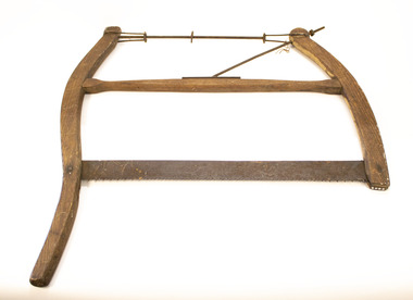 Clunes Museum
Tool - BOW SAW
... THE FRAME IS REINFORCED WITH METAL RODS THAT ALSO ADJUST THIS PIECE OF EQUIPMENT. ONE METAL ROD ACROSS THE TOPS STABILSES THE FRAME, ANOTHER ON AN ANGLE BRACES THE CENTRE WOODEN BAR. ...THE FRAME IS REINFORCED WITH METAL RODS THAT ALSO ADJUST THIS PIECE OF EQUIPMENT. ONE METAL ROD ACROSS THE TOPS STABILSES THE FRAME, ANOTHER ON AN ANGLE BRACES THE CENTRE WOODEN BAR. ...SHAPED WOODEN FRAME WITH SAW EDGE FOR PRUNING TREES OR CUTTING TIMBER. THE FRAME IS REINFORCED WITH METAL RODS THAT ALSO ADJUST THIS PIECE OF EQUIPMENT. ONE METAL ROD ACROSS THE TOPS STABILSES THE FRAME, ANOTHER ON AN ANGLE BRACES THE CENTRE WOODEN BAR. NONElocal history, trade, tools