Showing 25 items matching "cable drum"
-
 Melbourne Tram Museum
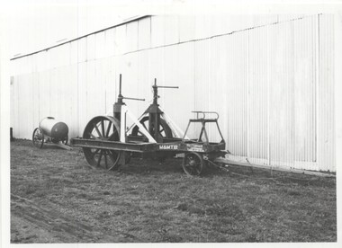
Photograph - MMTB horse drawn cable drum wagon, Keith Kings
... MMTB horse drawn cable drum wagon...cable drum...Photo shows the horse drawn MMTB cable drum carrying wagon...Photograph - MMTB horse drawn cable drum wagon at the TMSV...On rear in ink. TMSV – Horse drawn cable drum wagon... Photo shows the horse drawn MMTB cable drum carrying wagon ...Photo shows the horse drawn MMTB cable drum carrying wagon at the TMSV Museum at Bylands, mid 1970s. Has the MMTB identification, address and mass details painted on the vehicle. Behind the wagon is a Furphy water cart. Used to carry and distribute cable including overhead. Photo of the vehicle can be seen on page 68 of the book Destination City 3rd Edition.Yields information about the MMTB cable drum carrying wagon at Bylands.Photograph - MMTB horse drawn cable drum wagon at the TMSV Bylands Museum On rear in ink. TMSV – Horse drawn cable drum wagon at Bylands (Also Furphy water tank), Keith Kings photo. tramways, tmsv, bylands, horse drawn vehicles, overhead, cable drum -
 Bendigo Military Museum
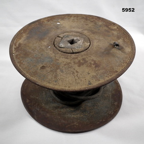
Equipment - CABLE DRUM, Hearl & Heaton & Sons Ltd, 1918
... CABLE DRUM...Cable Drum...This is a circular metal cable drum. The centre 'axle... return in WW1. WW1 Cable Drum On the side that has the cable exit ...This probably was used with single telephone cable earth return in WW1.This is a circular metal cable drum. The centre 'axle' is made a cylindrical piece of timber. It in turn, has a square metal bearing. This square metal bearing has a square hole in the centre 15 x 15 mm. This is held in place with 4 slotted screws. There is a small length of rubber covered cable exiting from one side of the drum. It is a 5 core cable. In the wooden drum is a metal sleeve. It can be slid around to reveal a metal screw terminal.On the side that has the cable exit can be seen, "HEARL & HEATON & SONS LTD 11 1918" ww1, cable drum -
 Glenelg Shire Council Cultural Collection
Photograph - Photograph - Portland Harbour, 30/08/1989
... of the cable-drum. Cable can be seen wound on to drum... side of metal wheel part of the cable-drum. Cable can be seen ...Port of Portland Authority ArchivesBack: B'30/8/89' - black textaport of portland archives, portland harbour -
 Friends of Kurth Kiln
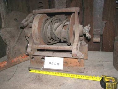
Winch
... Steel Rope Winch with Ratchet wheel. Cable Drum contains... wheel. Cable Drum contains ~6m of 10mm dia wire rope. Winch ...Steel Rope Winch with Ratchet wheel. Cable Drum contains ~6m of 10mm dia wire rope.Lettering on Gear Wheel - DAWN MFG CO - 2 TON AUSTRALIA -
 Friends of Kurth Kiln
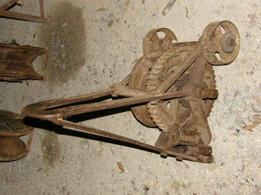
Tree Puller
... wheels, a cable drum and a large steel handle. Handle fits... stumps. Steel frame, two steel wheels, a cable drum and a large ...Winch Tool to pull tree stumps. Steel frame, two steel wheels, a cable drum and a large steel handle. Handle fits on square shaft of drum and ratchet arrangement -
 Flagstaff Hill Maritime Museum and Village
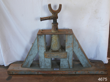
Jack
... Cable/rope-drum Jack, wooden stand with metal parts painted...-Museum Shipwreck-coast Flagstaff-Hill-Maritime-Village Cable/rope ...Cable/rope-drum Jack, wooden stand with metal parts painted greyflagstaff hill, warrnambool, shipwrecked-coast, flagstaff-hill, flagstaff-hill-maritime-museum, maritime-museum, shipwreck-coast, flagstaff-hill-maritime-village -
 Flagstaff Hill Maritime Museum and Village
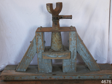
Jack
... Cable/Rope-drum Jack wooden stand with metal parts painted...-Museum Shipwreck-coast Flagstaff-Hill-Maritime-Village Cable/Rope ...Cable/Rope-drum Jack wooden stand with metal parts painted greyflagstaff hill, warrnambool, shipwrecked-coast, flagstaff-hill, flagstaff-hill-maritime-museum, maritime-museum, shipwreck-coast, flagstaff-hill-maritime-village -
 Melbourne Tram Museum
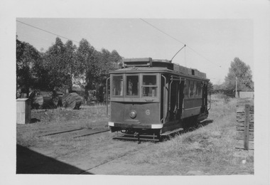
Photograph - VR Tram 6 at Elwood Depot, K McCarthy, 1 January 1951
... are cylindrical wooden cable drums, trees and other tramcars.... are cylindrical wooden cable drums, trees and other tramcars. Yields ...The photograph shows VR tram 6 on an outside track in long grass with trolley pole raised. In the mid ground are cylindrical wooden cable drums, trees and other tramcars.Yields information about the outside yard and VR tramcarsBlack and white photograph with notes on the rear.In biro and pencil on the rear "#6 at Elwood Depot 1-1-51 Brighton Line Copyright K McCarthy Photo No 783"tramcars, tram 6, vr tram, elwood depot, outside track -
 Melbourne Tram Museum
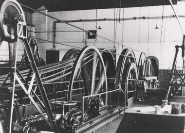
Photograph - Black and White photograph, 1937
... and cable drums. shows the detail of the means of transferring... winding mechanism and cable drums. shows the detail of the means ...Black and white photograph of the interior of a winding house or power house showing the cable winding mechanism and cable drums. shows the detail of the means of transferring the power from the engines to the cable itself and the mechanism of adjusting the cable tension. Dated 1937 - either the Collingwood cable or the Nicholson St cable. Photo by The Age.Has The Age copyright stamp on the rear - photo now out of copyright. and in the bottom corners "Age" and "1937"trams, tramways, cable trams, winding houses, power house -
Glenelg Shire Council Cultural Collection
Photograph - Photograph - Machinery, 30/08/1989
... Colour photo. Shows the metal wheel and cable on the drum...' - black texta Colour photo. Shows the metal wheel and cable ...Port of Portland Authority ArchivesBack: B'30/8/89' - black textaport of portland archives -
 8th/13th Victorian Mounted Rifles Regimental Collection
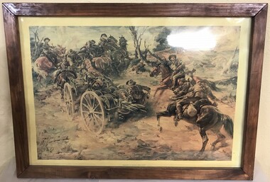
Print - Laying cable WWI, Signalers laying cable WWI, unknown
... telephone cable from a drum on a wagon.... a drum on a wagon. Signalers laying cable WWI Print Laying cable ...UnknownFramed print of a painting depicting WWI signallers laying telephone cable from a drum on a wagon.signaller, wwi, world war one, horse, wagon -
Glenelg Shire Council Cultural Collection
Photograph - Photograph - Machinery, 30/08/1989
... nuts. There is a steel cable on the drum.... nuts. There is a steel cable on the drum. Photograph Photograph ...Port of Portland Authority ArchivesBack: '30/8/89' - black textaport of portland archives -
Glenelg Shire Council Cultural Collection
Photograph - Photograph - Portland Harbour, n.d
... drum, the other three have cable and clain. The winches... portable metal winches in a row. One has cable only its drum ...Port of Porltand Authority Archivesport of portland archives, portland harbour -
 Australian Gliding Museum
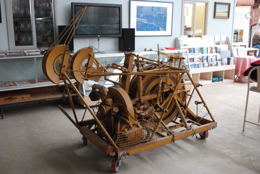
Machine - Winch - for auto tow launching cable laying and retrieval
... would automatically apply brake pressure to the cable drum... automatically apply brake pressure to the cable drum as the vehicle ...The auto tow launching mechanism was designed by Ray Jamieson of Cobram in the north of Victoria. The prototype was built the for the Corowa Gliding Club where it was used for some years. After Ray’s brother, Bert Jamieson, had witnessed the machine in use at Corowa, at Bert’s request, Ray built second one (the Museum’s exhibit) for use at Bacchus Marsh airfield. Bert lived in Melbourne at the time and was a member of the Victorian Motorless Flight Group (VMFG) which used Bacchus Marsh airfield. This occurred in the 1970s. The method of operation was to have the auto tow mechanism mounted in the back of a utility motor vehicle. The launching cable was attached to the glider. With the Volkswagen engine of the mechanism running, the tow vehicle would then drive along the runway to commence the launch. The mechanism would automatically apply brake pressure to the cable drum as the vehicle proceeded freely letting out the cable and then smoothly towing the glider into the air. When the launching cable reached a certain angle, the pilot would release the cable from the glider at which point the winching mechanism would automatically retrieve the cable in preparation for the next launch. This allowed quicker restarts and the flexibility of easily changing runways to suit the wind conditions. It made gliding a simple and cost-effective operation. Ray Jamieson and his son often used the prototype which they named “George” at Corowa in this way. With the exception of several demonstration launches, the Museum’s example of this type of device was not used by the VMFG at Bacchus Marsh due to rulings by the Department of Civil Aviation encouraging the use of aero tow launching at their site. As far as is known this is the only device of its type in the world and is indicative of the ingenuity found amongst the Australian gliding fraternity.Single drum and motorized drive mechanism mounted on a mobile steel frame.australian gliding, glider, sailplane, auto towing, launching, jamieson, corowa gliding club, victorian motorless flight group, vmfg -
Glenelg Shire Council Cultural Collection
Equipment - Wave Recording Equipment, n.d
... base. External float on wire cable attached to geared drum..., clipped to alloy base. External float on wire cable attached ...Port of Portland CollectionWave recording instrument. Manufacturer's label missing. Alloy lid with lifting handles on each end, clipped to alloy base. External float on wire cable attached to geared drum and recording mechanism. The float tube is missing, also parts of the recording equipment. Float measures 21 x 16 diameter.port of portland -
 Flagstaff Hill Maritime Museum and Village
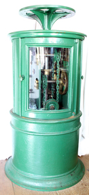
Machine - Dioptric Apparatus, mid 19th century
Before the introduction of electricity, lighthouses had a clockwork mechanism that caused the lens to rotate with a light source inside that was either powered by Kerosene or Colza oil. The mechanism consisted of a large weight attached by a cable through the centre of the lighthouse to the top where the cable wrapped around a barrel, drum or wheels that controlled the speed of the lights rotation by a clockwork mechanism. The keeper would crank the clockwork mechanism, which would lift the weight ready for the next cycle similar to an old grandfather clock mechanism. Once the weight lifted to its apex at the bottom of the first landing, the keeper would let it fall, which would pull on the cable, which would, in turn, operate a series of gears activating the rotation of the Fresnel optical lens, which would then rotate to create the lighthouse’s unique light speed of rotation characteristic. Creating a specific characteristic required a way to regulate the speed of the rotation, and was important as sailors could identify a particular light by its speed and time between flashes. The weight had to fall at a certain rate to create the proper rotation speed of the lens and a regulator within the mechanism accomplished this. History: From 1851, Chance Brothers became a major lighthouse engineering company, producing optical components, machinery, and other equipment for lighthouses around the world. James Timmins Chance pioneered placing lighthouse lamps inside a cage surrounded by Fresnel lenses to increase the available light output these cages, are known as optics and they revolutionised lighthouse design. Another important innovation from Chance Brothers was the introduction of rotating optics, allowing adjacent lighthouses to be distinguished from each other by the number of times per revolution the light flashes. The noted English physicist and engineer, John Hopkins invented this system while employed at Chance Brothers. Chance Brothers and Company was a glass works and originally based in Spon Lane, Smethwick, West Midlands England. The company became a leading glass manufacturer and a pioneer of British glass making technology. The Chance family originated in Bromsgrove as farmers and craftsmen before setting up a business in Smethwick near Birmingham in 1824. They took advantage of the skilled workers, canals and many other industrial advances taking place in the West Midlands at the time. Robert Lucas Chance (1782–1865), known as 'Lucas', bought the British Crown Glass Company's works in Spon Lane in 1824. The company specialised in making crown window glass, the company ran into difficulty and its survival was guaranteed in 1832 by investment from Chance's brother, William (1788 – 1856). William owned an iron factoring business in Great Charles Street, Birmingham. After a previous partnership that Lucas had dissolved in 1836, Lucas and William Chance became partners in the business which was renamed, Chance Brothers and Company. Chance Brothers invented many innovative processes and became known as the greatest glass manufacturer in Britain. In 1848 under the supervision of Georges Bontemps, a French glass maker from Choosy-le-Roi, a new plant was set up to manufacture crown and flint glass for lighthouse optics, telescopes and cameras. Bontemps agreed to share his processes that up to then had been secret with the Chance Brothers and stayed in England to collaborate with them for six years. In 1900 a baronetcy was created for James Timmins Chance (1814–1902), a grandson of William Chance, who had started the family business in 1771 with his brother Robert. Roberts grandson, James became head of Chance Brothers until his retirement in 1889 when the company became a public company and its name changed to Chance Brothers & Co. Ltd. Additional information: Lighthouses are equipped with unique light characteristic or flashing pattern that sailors can use to identify specific lighthouses during the night. Lighthouses can achieve distinctive light characteristics in a few different ways. A lighthouse can flash, which is when brief periods of light interrupt longer moments of darkness. The light can occult, which is when brief periods of darkness interrupt longer moments of light. The light can be fixed, which is when the light never goes dark. A lighthouse can use a combination of flashing, oscillating, or being fixed in a variety of combinations and intervals to create individual light characteristics. It is a common misconception that a lighthouse's light source changes the intensity to create a light characteristic. The light source remains constant and the rotating Fresnel lens creates the various changes in appearance. Some Fresnel lenses have "bulls-eye" panels create beams of light that, when rotated between the light and the observer, make the light appear to flash. Conversely, some lenses have metal panels that, when rotated between the light and the observer, make the light appear to go dark. This Dioptric clockwork apparatus used to turn a lighthouse optical lens is very significant as it is integral to a lighthouses operation, we can also look at the social aspect of lighthouses as being traditionally rich with symbolism and conceptual meanings. Lighthouses illustrate social concepts such as danger, risk, adversity, challenge and vigilance but they also offers guidance, salvation and safety. The glowing lamp reminds sailors that security and home are well within reach, they also symbolize the way forward and help in navigating our way through rough waters not just on the oceans of the world but in our personal lives be it financial, personal, business or spiritual in nature. Nothing else speaks of safety and security in the face of adversity and challenge quite the way a lighthouse does. Revolving dioptric clockwork apparatus used to turn a Fresnel optical lighthouse lens. A cylindrical cast metal pillar and cabinet painted green with 3 glass doors enclosing the top section. Inside the pillar/cabinet is a large clockwork mechanism used to turn and regulate a lighthouse light by means of weights and a chain attached to same. One door has the name "Adams Mare" in metallic dots similar to "Braille" to the inside edge of door frame.shipwrecked-coast, flagstaff-hill, flagstaff-hill-maritime-museum, flagstaff hill, maritime-museum, shipwreck-coast, warrnambool, flagstaff-hill-maritime-village, revolving dioptric mechanism, dioptric mechanism for lighthouse, lighthouse clockwork timing mechanism, acetylene lighthouse light mechanism, 19th century lighthouse mechanism, kerosene light, fresnel lenses, colza oil, chance brothers -
Glenelg Shire Council Cultural Collection
Tool - Tool - Hand winch, n.d
... drum with wire cable, iron winch handle can be located... winch, cast iron, steel, "A" frame structure, steel drum ...Port of Portland Collection. Unknown.Front: - Back: -port of portland archives -
Bendigo Historical Society Inc.
Photograph - UNKNOWN MINING PHOTOS - WINDING GEAR
... of winding gear. Top photo shows the winding drums with the cable... shows the winding drums with the cable on them. Bottom photo ...Black & white photocopies (2 on the one page) of photos of winding gear. Top photo shows the winding drums with the cable on them. Bottom photo shows the winding drums and a rectangular box section with hand rails around the edges.photo, unknown mining photos, winding gear -
 Bendigo Historical Society Inc.
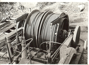
Photograph - WINDING ENGINE AT MONUMENT HILL MINE
... & Son) at Monument Hill Mine. Winding gear, large drum with wire... Hill Mine. Winding gear, large drum with wire cable wound ...Black and white photograph of a winding engine (Roberts & Son) at Monument Hill Mine. Winding gear, large drum with wire cable wound on, sitting on concrete base. Inscriptions: on back - lined paper, glued in centre 'Monument Hill Mine, Winding Engine, Roberts and Sons'.place, mining site, rope winding drum, mines and mining, equipment, mining equipment, bendigo, mines, mining, surface equipment -
 Puffing Billy Railway
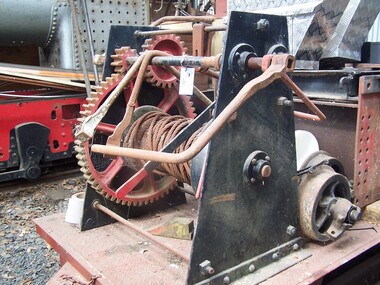
Hand Winch
Imported by Cameron, Sutherland & Seward Ltd. Machinery Merchants, Melbourne & Sydney, this example is of the type of hand winch used by the Australian Industries and timber workers in the Australian bush. The central rotating drum is operated by three interacting cog wheels. The metal cable is wound onto the central drum.Historic - Hand Winch type of hand winch used by the Australian Industries and timber workers in the Australian bush.Hand Winch made of wrought iron, metal and ironhand, winch -
 Puffing Billy Railway
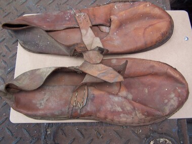
Clothing - Shoes
These leather soled shoes were used by railway workers undertaking work on overhead electrical cables and HV boxes. Known as "slippers" they were provided just inside explosives vans and worn to stop metal protectors on shoes scraping across metal floor and possibly causing a spark and a explosion. info from Syd Coles : on Explosives Slippers Beaufort station used to get a explosive wagon with drums of gelignite regularly slipper type shoes were in a little box built into the inside wall of the wagon....A Special powdervan key was sent from H/OFFICE as a VALUE which each person handling it had to sign for it.....It would arrive on the early down Passenger Train ex Melbourne...then the "P" wagon was unloaded....Prior to the wagon leaving a Railway Internal telegram was sent to the SM @Beaufort giving the wagon number...consignee (owners of dynamite) contents and the KEY number which would be sent....When all unloaded the KEY sent back as a VALUE...a Internal telegram sent as to KEY number and train it was despatched on....fair bit of security.but couldn't afford to lose a KEY as they fitted all the LOCKS used on the EXPLOSIVE "P" wagons whatever Stations they went to.Historic - Victorian Railways - leather soled shoesLeather soled slip-on shoes, with single strap across bridge of foot and featuring stitchwork along edges.VR & arrow symbolpuffing billy, victorian railways, leather soled shoes, railway slippers, explosives, worker safety, linesmen -
 Ballarat Tramway Museum
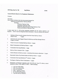
Manual, Doug Prosser, "General Electric Data for Car Equipment Maintenance", 1998
A black plastic folder containing a set of 38 General Electric Data Sheets for MMTB and tramway trust equipment, dated July 8 1924. Contained in folder with flexible clips. Pages have been punched with four holes. Copy of document made for BTM Feb 1998 by Doug Prosser. For scan of list - see btm780sheet.pdf General Electric Data for Car Equipment Maintenance Contents For scan see btm780d1 (5 pages) Title sheet Data contents summary sheet showing manual prepared for Melbourne & Metropolitan Tramways Board Including Footscray Tramway Trust Hawthorne Tramways Trust Melbourne, Brunswick and Coburg Tramway Trust Prahran and Malvern Tramways Trust. 2 sheets dated July 8, 1924 giving equipment schedules for the various operators, and diagrams. - hard to read the background sheet information. Does not reference the tramcars. For scan see btm780d2 (54 sheets - items 1 to 27) 1. Methods of Removing the Armature from Box Frame Railway Motors Dated 9/1924, 7 pages 2. Instructions for order Magnet Frames for Railways and Mine Haulage Motors 2 pages, not dated 3 Winter Covers for Ventilated Railway Motors - 2 pages 4 Better Commutation for Railway Motors - 1 page 5 Commutator Grooving Machines - 1 page 6 Railway Motor Armature Coils - 2 pages 7 Carbon Brushes for Railway motors - including brush pressure adjustment - 2 pages 8 Renewable Carbon-Way Brush holders for Railway Motors - 2 pages 9 Commutator Grooving Machines (2nd version) - 2 pages 10 The Repair of Railway Motor Commutators - 3 pages 11 Dimensions of Electrical Apparatus used with 600-volv Type PC railway control equipment, (Sheet 15380, dated 2/1/1924) - 1 sheet including · US-13-E Trolley Base, · MS-118-A main switch, · MA-13-F Fuse Box, · MD3 - lightning Arrester, · BJ-386-B Distributing Box, · Type BG Railway Resistors. 12 Connections of Type KM-63-BR Railway Controllers and Equipment - Drawing 15257, 1 page, dated 1/3/1921 with dimension details on rear of type K-63-BR railway controller equipment including: · SG Resister, · BK-13-A Insulator, · MR11 - Circuit breaker, · MD3 - Lightning Arrester box, · K63-BR Controller, · US15C Trolley Base. 13 Method of Supporting Railway Resistors using Porcelain Bolt insulators for 600 and 1500 Volt Work. Drawing dated 1/11/1923, No. 15249B - 1 page 14 Dimensions of Electrical Apparatus used with 600-volv Type M railway control equipment, (Sheet 15381, dated 2/1/1924) - 1 sheet including · US-13-E Trolley Base, · MS-118-A main switch, · MA-13-F Fuse Box, · MD3 - lightning Arrester, · BJ-386-B Distributing Box, · Type BG Railway Resistors. 15 Dimensions of Electrical Apparatus used with 600Volt, Type PC Railway Control Equipment. Drawing No. 15382, dated 2/1/1924. Includes: · C129-A Master Controller, · DA82C Coupler sockets, · MS-14-G switch, · MS-46-H switch. 16 Dimensions of Electrical Apparatus used with 600-volv Type M railway control equipment, (Sheet 15383, dated 2/1/1924) - 1 sheet including · C-169-A Controller · DA-69-B Coupler Socket and DC-66-C Coupler Plug · MS-14-G Switch · MS-46-H-Switch 17 Method of Making Tap Connections for Car Cables -= SD 15468, 1/11/1924, 1 page 18 The Repair of 600 Volt Railway Motor Armatures, 64408, 9/2/1924, 4 pages 19 Proper Method of Mounting and Dismounting Railway Motor Pinions. - 2 pages 20 Pinion Pullers for Railway Motors - 2 pages, dated 8/1/1924. 21 The Care of Railway Motor Bearings - 4 pages 22 Oil Scraper Rings for Air Compressors - 64590 - May 1924 - 1 page 23 Finger Bases for type K 63 controller 1 page 24 Adjustment of Drum Controller fingers - 29/1/1924, 64600A - 1 page 25 Star Wheels for Type K Controllers - 64603 - 1 page 26 Soldering Aluminium Controller Cylinder Castings - 2 pages 27 Porcelain Bolt Insulators for Railway Service - and drawing on rear showing mounting arrangement of resistor Grids - 2 pages. For scan see btm780d3 (13 pages) 28 Connections of Armature and Field Winding for GE-201-F and GE 263A railway motors. DS37869 29 Connections of Armature and Field Winding for GE-201-I railway motors. K1629303 30 Connections of Armature and Field Winding for GE-202 motor, DS 10472 31 Connections of Armature and Field Winding for GE-203 A and GE 226 railway motors. DS23869. 32 Connections of Armature and Field Winding for GE-241 motors - K1629077 33 Connections of Armature and Field Winding for CP25A Air compressor 34 Connections of Armature and Field Winding for CP27A Air compressor 35 Connections of Armature and Field Winding for GE-258 and GE 264 railway motors. K1629343. 36A- Dimensions of Type K-63-BR Railway Controller Equipment 36 US-13-E Trolley Base for Railway Service - 3/1/1923, 64823 - 2 pages 37 Copy of M&MTB (Eastern System) Certificate of Competency as Motorman. 38 Photocopies of a series of four photos of 22E trucks under an SEC tramcar. For scan see btm780d4 (40 pages) 39 Sprague G-E Multiple Unit Control, Type PC, Instruction Book 84772 - Oct. 1922 - 40 Pages. Images of sheets added 2-11-15 trams, tramways, general electric, motors, controllers, trolley pole bases -
 Ballarat Tramway Museum
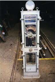
Photograph - Colour Photograph/s, Warren Doubleday, mid 12/1997
Yields information about a piece of the original equipment from the ESCo Ballarat power station.Colour photograph of the ESCo Wendouree Parade power station - DC face plate starter for one of the rotary converters - DC hand operated drum and multiple lever panel" - see Jan. 1998 issue of Fares Please! for details of the donation and a copy of the photograph as used. Photo taken by Warren Doubleday. Printed on Kodak Paper. Photo taken mid Dec. 1997. Photos of cabinet with doors opened and signs added 2/4/2018. Images .1 - Brookhirst makers plate with Patent Nos. .2 - Machine with doors open .3 - wiring diagram .4 - Brookirst cabinet latch at the bottom of the machine. .5 - Safety sign re opening the doors. .6 - bottom section of cabinet with cable found in machine .7 - top half of machine .8 - similar to .6 .9 - close up of the cable. See January 1998 Fares Please!esco, power station, rotary converters -
 Melbourne Tram Museum
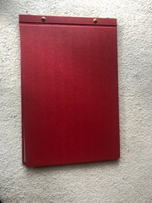
Document - Folder, William Pollock, "The Melbourne Cable Tramway System", c1940
... – Curve or Conical drum – htd4715i17.jpg 13 – Cable Separating... – htd4715i17.jpg 13 – Cable Separating pulley or cone line drum ...Folder - heavy red covers with two screw sets containing a photocopy of a report by William Pollock, prepared after the closure of the cable tram system titled ""The Melbourne Cable Tramway System". Image numbers listed: Folder – htd4715i1 Inside of folder – htd4715i2.jpg Report –Photocopy of a 14 foolscap sheets, paper titled “The Melbourne Cable Tramway System” by William Pollock, describing the system in detail, listing 26 appendices. Has notes on each Power Station, including a table of opening, closing, power produced and cables, fuel, permanent way (track), cables, underground gear, tunnels, flooding and the grip. Image – htd4714i3.pdf Appendix 1 – Handwritten table “Cost the Melbourne Tramway System” – photocopied special size sheet folded. See image htd4715i4.jpg 2 – Drawing – Typical Power House layout - image htd4715i5.jpg 3 – Drawing – Head of Cable Driver – htd4715i6.jpg 4 – Drawing – Rope Drive – htd4715i7.jpg 5 – Photocopy of a Fuel and Water test sheet for the Esplanade Power House – two sheets – 14/5/1918 – htd4715i8.jpg and htd4715i9.jpg 6 – Section of Cable Tram track – htd4715i10.jpg 7 – Tar Burner used by MTOC 1893 – 1900 - htd4715i11.jpg 8 – Yoke Bracket for line drums – A1 Pulley – htd4715i12.jpg 9 – Tunnel Yoke – htd4715i13.jpg 10 – Elevating Wheel or Pulley with shield plate – htd4715i14.jpg 11 – Curve Pulleys, curve drum and rubbing bar – 2 sheets – htd4715i15.jpg and htd4715i16.jpg 12 – Curve or Conical drum – htd4715i17.jpg 13 – Cable Separating pulley or cone line drum – htd4715i18.jpg 14 – Yoke Pulley or General Pulley – htd4715i19.jpg 15 – Yoke Bracket for Drums – htd4715i20.jpg 16 – Automatic Switch Gear – htd4715i21.jpg 17 – Hand operated switch gear – htd4715i22.jpg 18 – Hand pickup – htd4715i23.jpg 19 & 20 – Photo of bunched strands and damaged cable – htd4715i24 21 – Diagram of Rope – Clarendon St Rope No. 41 – htd4715i25.jpg 22 – Strand Alarm – htd4715i26.jpg 23 – Rope History – two sheets – htd4715i27 and htd4715i28.jpg 24 – Rope Splice – htd4715i29.jpg 25 – Cable Grip – htd4715i30.jpg 26 – Crown Pulley – two sheets – htd4715i30 and htd4715i31trams, tramways, drawings, tramcars, cable trams, trackwork, mto co, reports -
 Merri-bek City Council
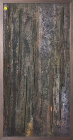
Mixed media - Callistemon charcoal and ink on marine ply, Brian McKinnon, Bush Fire I “Redgum Sleeper”, 2019
... furniture was all makeshift old banana boxes for chairs, cable drums ...