Showing 20 items matching "circuit operations"
-
 Moorabbin Air Museum
Book - Flight training - general aviation, The Flying Training Manual for Student, Private & Commercial Pilots
... ...Circuit operations...Flight training - general aviation The aeroplane Before & after flight Your first flight The controls Taxiiing Straight & level Climbing Descending Turning Stalling & slow flight Spinning Standard take off & climb to downwind leg Circuit operations First solo Advanced turning Low level flying Pilot navigation Using the flight instriuments Specific aeroplane type Exercise briefings for student , commercial & private pilots, circa 1989 The Flying Training Manual for Student, Private & Commercial Pilots Book Flight training - general aviation ...Exercise briefings for student , commercial & private pilots, circa 1989non-fictionExercise briefings for student , commercial & private pilots, circa 1989the aeroplane, before & after flight, your first flight, the controls, taxiiing, straight & level, climbing, descending, turning, stalling & slow flight, spinning, standard take off & climb to downwind leg, circuit operations, first solo, advanced turning, low level flying, pilot navigation, using the flight instriuments, specific aeroplane type -
 Tarnagulla History Archive
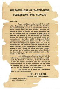
Circular from Deputy Postmaster General, Improper Use of Earth-Wire Contention For Circuit, 23rd March 1870
... A circular from the Deupty Postmaster General with title Improper Use of Earth-Wire Contention For Circuit. Relates to operation of the telegraph. Original, not copy....Tarnagulla History Archive Tarnagulla Public Hall 69-71 Commercial Rd Tarnagulla goldfields Donald Clark Collection. tarnagulla sandy creek postmaster post office postal regulations telegraph A circular from the Deupty Postmaster General with title Improper Use of Earth-Wire Contention For Circuit. Relates to operation of the telegraph. Original, not copy. ...Donald Clark Collection. A circular from the Deupty Postmaster General with title Improper Use of Earth-Wire Contention For Circuit. Relates to operation of the telegraph. Original, not copy.tarnagulla, sandy creek, postmaster, post office, postal regulations, telegraph -
 Melbourne Tram Museum
Manual, MAN, "MAN Buses - Driver's Handbook" and, "Gearbox flaw cripples bus fleet", mid 1980's
... Has a table of contents, item reference list and electric circuit diagrams. Covers the operation, equipment, driving, cold weather operation, maintenance, lubrication, fuels, general car and maintenance. .2 - newspaper clipping from The Age ""Gearbox flaw cripples bus fleet", dated 26/3/1987, by Tony Harrington, Transport Reporter reporting on the withdrawal of 20 buses from North Fitzroy - replacement parts no longer being manufactured. ...Has a table of contents, item reference list and electric circuit diagrams. Covers the operation, equipment, driving, cold weather operation, maintenance, lubrication, fuels, general car and maintenance. .2 - newspaper clipping from The Age ""Gearbox flaw cripples bus fleet", dated 26/3/1987, by Tony Harrington, Transport Reporter reporting on the withdrawal of 20 buses from North Fitzroy - replacement parts no longer being manufactured. ....1 - Manual - 116 pages centred stapled - titled "MAN Buses - Driver's Handbook". Has a table of contents, item reference list and electric circuit diagrams. Covers the operation, equipment, driving, cold weather operation, maintenance, lubrication, fuels, general car and maintenance. .2 - newspaper clipping from The Age ""Gearbox flaw cripples bus fleet", dated 26/3/1987, by Tony Harrington, Transport Reporter reporting on the withdrawal of 20 buses from North Fitzroy - replacement parts no longer being manufactured. Also has a loose note about the radiator capacity.trams, tramways, buses, maintenance, man, manual, gears -
 Kiewa Valley Historical Society
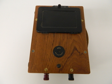
Meter Millivolt, after 1950
... It was used to measure very small voltages associated with the operation of the various Hydro Generators. The readings were able to be shown by the resistor in use in the current circuit. ...It was used to measure very small voltages associated with the operation of the various Hydro Generators. The readings were able to be shown by the resistor in use in the current circuit. ...This milli-volt meter was manufactured after 1950 and used by the SEC Vic (Kiewa Hydro Electricity Scheme) from that date until late 1900's. It was used to measure very small voltages associated with the operation of the various Hydro Generators. The readings were able to be shown by the resistor in use in the current circuit. During this time period, high quality testing instruments were either sourced from Europe or England.This milli-volt meter is very significant to the Kiewa Valley as it was used by those electrical technicians, who were part of the Kiewa Hydro Scheme. An "off spin" from the Scheme was the beginning of an explosion in "human" resources into the Kiewa Valley. This influx of population transformed the region from that of a basically quiet rural region to one which evolved into both industrial and larger residential community. This evolution in the Kiewa Valley created a change, not only in the "physical" landscape(better roads and infrastructure), but also the socio-economic growth within the Valley allowing other "tourist" based industries to expand within the valley and Alpine areas.This millivolts DC meter was used in the 1950's. It is contained in a wooden box and has two coloured (red/black, positive and negative) screw tight knobs which have bake-lite connections. It also has a covered (black tin) view meter marked from zero to 10 millivolts. Underneath this and within a round bake-lite is a small adjustment screw. The top of the box is fastened onto the main structure by six brass screws. The back of the structure is fastened by eight brass screws and there are four small bake-lite rest knobs.On the face of the millivolt compartment , and at the top "TO BE USED WITH DIAL HORIZONTAL TEMP. COEF. +- .08 % PER oC. Underneath the scale "MILLIVOLTS D.C. F.G." (LEAD RESIS. .05 OHMS)" underneath and to the left "MADE IN ENGLAND BY" "EVERSHED & VIGNOLES Ltd" and to the right "No. 857842" underneath Regd. TRADE MARK MEGGERkiewa valley tourism, victorian alps, alternate energy supplies, alpine population growth -
 Kiewa Valley Historical Society
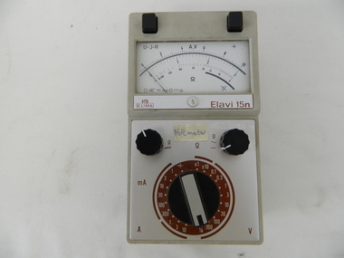
Meter Multi General Purpose, circa mid to late 1900's
... It was used to measure very small voltages associated with the operation of the various Hydro Generators. The readings were able to be shown by the resistor in use in the current circuit. ...It was used to measure very small voltages associated with the operation of the various Hydro Generators. The readings were able to be shown by the resistor in use in the current circuit. ...This general purpose Multi-meter was manufactured after 1950 and used by the SEC Vic (Kiewa Hydro Electricity Scheme) from that date until late 1900's. It was used to measure very small voltages associated with the operation of the various Hydro Generators. The readings were able to be shown by the resistor in use in the current circuit. During this time period, high quality testing instruments were either sourced from Europe or England. This particular meter was manufactured in the Netherlands. This type of "old" analogue meter was replaced by digital meters whose electronic components are a fraction of the size of the older analogue ones.This analog General Purpose multi-meter is quite a large (for handheld mobile) apparatus which permits the easy monitoring of electrical variations within the large SEC Victoria Hydro Scheme's electrical generators. These generators are powered by the hydro force of "stored" water at a higher altitude. The establishment of both the NSW and Victorian Hydro schemes was achieved from the mid 1900's to the 1960's. At this point in time the need for additional power sources to quench both an industrial and domestic demand for electricity was purely an economic and not and environmental (carbon reduction) factor. This hydro scheme was instigated by "the Government of the day" as a bold move and was the major force of the World War II refugee and "technical" workforce inclusion of skilled and unskilled migration into the Australian environment. Although this mass "invasion" of workers with families was thought of in some circles as intrusive, the expansion of population post war years and its integration into the Australian rural sector, produced the multi- lingual multi-cultural diversity of later years.This General Purpose Multimeter is an analogue meter i.e. it has a needle arm that moves across a scale of divisions. This is a large(hand held) device due to the mechanical movement system within and the large size of its electronic components of its circuitry.There are two black bake-lite push buttons operating the wire inserts Positive/negative leads at the top. The meter (protected with a glass window) has clearly marked graduations (top - volts, bottom amperes). Below this are two bake-lite dials (left "potentiometer the right one measuring range selector). Below this is a "dial" switch to input the desired resistance measuring range "V" Front "H&B ELIMA" and to the right Elavi 15n. 0n the front side is a label "STATE ELECTRICITY COMMISSION OF VICTORIA TRANSMISSION DEPT E.C.No." On the bottom of the base is a stenciled layout of the battery "layout" including the fuse . The information notice is presented in five languages starting with German, English,French, Italian, Spanish and Dutchsec vic kiewa hydro scheme, alternate energy supplies, alpine population growth -
 Kiewa Valley Historical Society
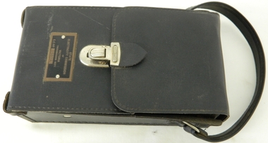
Case for G.P. Multimeter, Circa 1950
... It was used to measure very small voltages associated with the operation of the various Hydro Generators. The readings were able to be shown by the resistor in use in the current circuit. ...It was used to measure very small voltages associated with the operation of the various Hydro Generators. The readings were able to be shown by the resistor in use in the current circuit. ...This leather case holder for a general purpose Multi-meter( KVHS 0307 (A)) was manufactured after 1950 and used by the SEC Vic (Kiewa Hydro Electricity Scheme) from that date until late 1900's. It was used to measure very small voltages associated with the operation of the various Hydro Generators. The readings were able to be shown by the resistor in use in the current circuit. During this time period, high quality testing instruments were either sourced from Europe or England. This particular carry case was manufactured in the Netherlands. This carry case for an analog General Purpose multi-meter which is quite a large (for a handheld mobile) apparatus.The bag however permits the easy monitoring of electrical variations within the large SEC Victoria Hydro Scheme's electrical generators. These generators are powered by the hydro force of "stored" water at a higher altitude. The establishment of both the NSW and Victorian Hydro schemes was achieved from the mid 1900's to the 1960's. At this point in time the need for additional power sources to quench both an industrial and domestic demand for electricity was purely an economic and not and environmental (carbon reduction) factor. This hydro scheme was instigated by "the Government of the day" as a bold move and was the major force of the World War II refugee and "technical" workforce inclusion of skilled and unskilled migration into the Australian environment. Although this mass "invasion" of workers with families was thought of in some circles as intrusive, the expansion of population post war years and its integration into the Australian rural sector, produced the multi- lingual multi-cultural diversity of later years.This leather case is to provide protection for this mobile G.P. Multimeter, therefore it is made from thick leather. It has a carrying strap from a thick "D" chromed link. This link is fastened to the main cover by a looped leather strip with a black coloured rivet. All the fasteners are either chrome or black coloured rivets. The front, which when opened back exposes fully the inside of the case. It is clip fastened to the lower section of the front piece which also can be pushed back allowing the meter to be removed from the frontal position. There is a strip retaining strap slightly higher from the mid point. This is fasted by a black press stud. There are two "L" shaped tin protrusions allowing the meter to slide only down the case until it rests on these shelves. This provides for an empty space for minimal storage,.On the front bottom and below the clasp is a tag "STATE ELECTRICITY COMMISSION OF VICTORIA TRANSMISSION DEPT."sec vic kiewa hydro scheme, alternate energy supplies, alpine population growth -
 Eltham District Historical Society Inc
Photograph - Black and White Print, NASA, Tiros II - Taken from above with cover removed, 1960
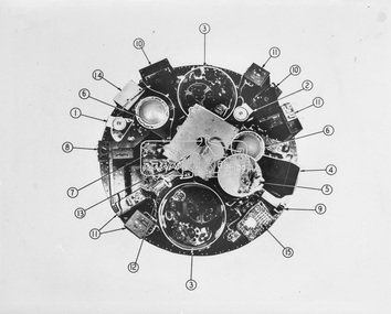
... operations sequence timing 7. Relays for magnetic stabilisation for altitude 8. Control box for electronics 9. Infra red horizon scanner 10. Electronic camera circuits...operations sequence timing 7. Relays for magnetic stabilisation for altitude 8. Control box for electronics 9. Infra red horizon scanner 10. Electronic camera circuits ...On reverse: Tiros II - Taken from above with cover removed: 1. Wide angle TV camera 2. Narrow angle TV camera 3. TV tape recorders 4. Infra red - 5 channel radiometer 5. Infra red electronics 6. Electronic operations sequence timing 7. Relays for magnetic stabilisation for altitude 8. Control box for electronics 9. Infra red horizon scanner 10. Electronic camera circuits 11. Electronic TV tape circuits 12. Telemetry switches 13. Antenna diplexer (covering storage batteries) 14. Automatic signal generator 15. Fuse board and current regulatoralan gardiner collection, space industry, 1960, satellite, tiros ii -
 Federation University Historical Collection
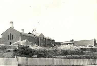
Photograph - Photograph - Digital, Geoff Little, Ballarat Gaol Under Demolition, 1968, 1968
... It is proposed, as soon as practicable, to extend the operation of the school so as to impart instruction in those branches of technical science which may be considered most likely to exert a beneficial influence on the prosperity of Victoria." School was in a disused Circuit...It is proposed, as soon as practicable, to extend the operation of the school so as to impart instruction in those branches of technical science which may be considered most likely to exert a beneficial influence on the prosperity of Victoria." School was in a disused Circuit ...The Ballarat Gaol was one of the earliest gaols. Building commenced in 1856 and was completed in 1862. It provided accommodation for 74 prisoners - male and female. The materials use to build the gaol were locally quarried basalt combined with local bricks. At that time there were about 14 brick making plants in Ballarat. 1870 saw the opening of the School of Mines, Australia's third oldest tertiary institution. The purpose of the school was "to impart instruction in the various branches of science relating to mining engineering. It is proposed, as soon as practicable, to extend the operation of the school so as to impart instruction in those branches of technical science which may be considered most likely to exert a beneficial influence on the prosperity of Victoria." School was in a disused Circuit Court House in Lydiard Street South. Sir Redmond Barry was first President of the School of Mines Council.Seven black and white and sepia photographs of the Ballarat Gaol under demolition. Progressive demolition showing rubble and machinery used. Gift of photographer. ballarat gaol, ballarat school of mines, gaol, basalt, local bricks, prisoners, circuit court house, mining engineering, sir redmond barry, lydiard street, tertiary institution, geoff little -
 Ballarat Tramway Museum
Document - Training, "Safety First - Section 1", c1974
... circuits, line breakers, insulated trams, trolley poles, light bulbs, broken trolley wires and fallen wires around trams. Section 2 - "instructions to be Observed by members and workers working on track maintenance". Possibly prepared for use by the BTPS, c1974. Demonstrates a Safety document for use by tramway crews and workers. tramways tramcars operations ...Document retyped from possibly an SECV training document titled "Safety First" outlining tram driving safety practices, awareness for motormen, electrical aspects, tram circuits, line breakers, insulated trams, trolley poles, light bulbs, broken trolley wires and fallen wires around trams. Section 2 - "instructions to be Observed by members and workers working on track maintenance". Possibly prepared for use by the BTPS, c1974.Demonstrates a Safety document for use by tramway crews and workers.Document - typed 6 Quarto pages - original.tramways, tramcars, operations, passenger services, ballarat, training -
 Ballarat Tramway Museum
Document - Instruction Book, Westinghouse Brake Company of Australasia Limited and The Westinghouse Brake & Saxby Signal Co. Ltd. of 82 York Road and Kings Cross London, "Westinghouse Railway Operating Data", 2000
... Care and repair of commutators 1 Undercutting commutators 2 Railway Motor carbon brushes 3 Brush holders 4 Flashing of railway motors 5 Soldering railway armatures 6 Armature Winding 7 Banding armatures 8 Railway Motor Bearings 9 Lubrication of railway motor bearings 10 How to babbitt motor bearings 11 Oil, grease and waster for motors and gears 12 Saturation of motor bearing waste 13 Testing Polarity of Field Coils 14 Charging of storage batteries on Interurban & street rail cars 15 Precautions to be taken with blower installations on motor cars 16 Putting on Railway Motor Pinions 17 How to take armatures out of box frame motors 18 Dipping and Baking of Railway Motors 19 War time dipping and baking outfits 20 Dipping and baking railway motors will decrease troubles 21 Protection of Motor Bearings from Dust 25 Winter Operation of Railway Motor equipments 26 Installation of Air piping to prevent freezing 27 Maintenance of Traction Brake Equipment 28 Maintenance of controller fingers and contacts 29 Hand operated circuit breakers 30 Railway Motor Testing I 31 Railway Motor Testing II 33 Railway Motor Testing III 35 Railway Motor Testing IV 36 Railway Motor Testing V 37 Removing and replacing railway motor armature shaft 39 Mounting and Maintenance of car resistors 40 Lubrication of control apparatus 41 Maintenance of fuse boxes for railway service 42 Does it pay to dip and bake armatures 43 Dipping and Baking as a financial asset 44 Shop Organisation 45 Tinning Malleable Iron Bearing shells 46 Life of armature bearings or railway motors 47 The assembly of complete sets of commutator segments 48 Electric welding as a factor in reclamation 50 Metal to Metal press, shrink and clamping fit allowances 52 Life of railway motor carbon brushes 54 General information of grid resistance design for the operating man 56 Stopping a car by braking with the motors 57 Railway Motor shafts and their maintenance 58 Axle collars 59 Gear cases 60 Ventilated railway motors 62 Revamping Loose armature bearings 64 Life of axle bearings of railway motors 65 Heat-treated bolts for railway service 66 Document imaged over 7 parts 7-9-2016 - see hi res files. ...Care and repair of commutators 1 Undercutting commutators 2 Railway Motor carbon brushes 3 Brush holders 4 Flashing of railway motors 5 Soldering railway armatures 6 Armature Winding 7 Banding armatures 8 Railway Motor Bearings 9 Lubrication of railway motor bearings 10 How to babbitt motor bearings 11 Oil, grease and waster for motors and gears 12 Saturation of motor bearing waste 13 Testing Polarity of Field Coils 14 Charging of storage batteries on Interurban & street rail cars 15 Precautions to be taken with blower installations on motor cars 16 Putting on Railway Motor Pinions 17 How to take armatures out of box frame motors 18 Dipping and Baking of Railway Motors 19 War time dipping and baking outfits 20 Dipping and baking railway motors will decrease troubles 21 Protection of Motor Bearings from Dust 25 Winter Operation of Railway Motor equipments 26 Installation of Air piping to prevent freezing 27 Maintenance of Traction Brake Equipment 28 Maintenance of controller fingers and contacts 29 Hand operated circuit breakers 30 Railway Motor Testing I 31 Railway Motor Testing II 33 Railway Motor Testing III 35 Railway Motor Testing IV 36 Railway Motor Testing V 37 Removing and replacing railway motor armature shaft 39 Mounting and Maintenance of car resistors 40 Lubrication of control apparatus 41 Maintenance of fuse boxes for railway service 42 Does it pay to dip and bake armatures 43 Dipping and Baking as a financial asset 44 Shop Organisation 45 Tinning Malleable Iron Bearing shells 46 Life of armature bearings or railway motors 47 The assembly of complete sets of commutator segments 48 Electric welding as a factor in reclamation 50 Metal to Metal press, shrink and clamping fit allowances 52 Life of railway motor carbon brushes 54 General information of grid resistance design for the operating man 56 Stopping a car by braking with the motors 57 Railway Motor shafts and their maintenance 58 Axle collars 59 Gear cases 60 Ventilated railway motors 62 Revamping Loose armature bearings 64 Life of axle bearings of railway motors 65 Heat-treated bolts for railway service 66 Document imaged over 7 parts 7-9-2016 - see hi res files. ...Photocopy of 54 data sheets published by Westinghouse Electric & Manufacturing Company of East Pittsburgh Pa, USA c1920. Consists of plastic cover, header page with Westinghouse logo, contents sheets (2 pages), forward, 67 pages (single side photocopy) and heavy rear card cover bound with a green comb binder. Original material lent by Craig Tooke of the Melbourne Tramcar Preservation Association at Haddon. Photocopied by Warren Doubleday March 2000. List of contents produced 30/6/2000 and then bound. Contains data sheets regarding motors, commutators, brushes, armatures, bearings, field coils, pinions, lubrication, air piping, axle collars, resistance grids, gear cases and other technical information. Westinghouse Railway Operating Data 30/6/2000 List of Contents Page No. Care and repair of commutators 1 Undercutting commutators 2 Railway Motor carbon brushes 3 Brush holders 4 Flashing of railway motors 5 Soldering railway armatures 6 Armature Winding 7 Banding armatures 8 Railway Motor Bearings 9 Lubrication of railway motor bearings 10 How to babbitt motor bearings 11 Oil, grease and waster for motors and gears 12 Saturation of motor bearing waste 13 Testing Polarity of Field Coils 14 Charging of storage batteries on Interurban & street rail cars 15 Precautions to be taken with blower installations on motor cars 16 Putting on Railway Motor Pinions 17 How to take armatures out of box frame motors 18 Dipping and Baking of Railway Motors 19 War time dipping and baking outfits 20 Dipping and baking railway motors will decrease troubles 21 Protection of Motor Bearings from Dust 25 Winter Operation of Railway Motor equipments 26 Installation of Air piping to prevent freezing 27 Maintenance of Traction Brake Equipment 28 Maintenance of controller fingers and contacts 29 Hand operated circuit breakers 30 Railway Motor Testing I 31 Railway Motor Testing II 33 Railway Motor Testing III 35 Railway Motor Testing IV 36 Railway Motor Testing V 37 Removing and replacing railway motor armature shaft 39 Mounting and Maintenance of car resistors 40 Lubrication of control apparatus 41 Maintenance of fuse boxes for railway service 42 Does it pay to dip and bake armatures 43 Dipping and Baking as a financial asset 44 Shop Organisation 45 Tinning Malleable Iron Bearing shells 46 Life of armature bearings or railway motors 47 The assembly of complete sets of commutator segments 48 Electric welding as a factor in reclamation 50 Metal to Metal press, shrink and clamping fit allowances 52 Life of railway motor carbon brushes 54 General information of grid resistance design for the operating man 56 Stopping a car by braking with the motors 57 Railway Motor shafts and their maintenance 58 Axle collars 59 Gear cases 60 Ventilated railway motors 62 Revamping Loose armature bearings 64 Life of axle bearings of railway motors 65 Heat-treated bolts for railway service 66 Document imaged over 7 parts 7-9-2016 - see hi res files. trams, tramways, westinghouse, motors, data sheets, technical information -
 Eltham District Historical Society Inc
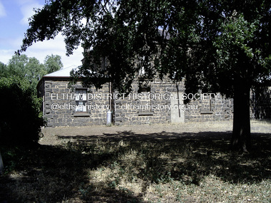
Photograph - Digital Photograph, Russell Yeoman, Carisbrook Jusice Precinct, 2005
... circuit as Maryborough and Dunolly. Design: It was designed in a similar style to the Maryborough courthouse but was constructed of bluestone. Closure & Reuse: Due to declining use, it was closed and sold in 1925, after which it became the Carisbrook Masonic Lodge. Police Station: The associated Carisbrook police camp was largely abandoned in 1881, with operations...circuit as Maryborough and Dunolly. Design: It was designed in a similar style to the Maryborough courthouse but was constructed of bluestone. Closure & Reuse: Due to declining use, it was closed and sold in 1925, after which it became the Carisbrook Masonic Lodge. Police Station: The associated Carisbrook police camp was largely abandoned in 1881, with operations ...Comparitive example from the mid 1880s with the Eltham Justice Precinct of 1859/1860. AI Overview - The historical Carisbrook Court House was a significant component of the local justice system in the mid-19th century, built in 1858 of bluestone to serve as a Court of General Sessions and Court of Mines for the area. Key Historical Details: Construction: The courthouse was built in 1858 and was part of the same circuit as Maryborough and Dunolly. Design: It was designed in a similar style to the Maryborough courthouse but was constructed of bluestone. Closure & Reuse: Due to declining use, it was closed and sold in 1925, after which it became the Carisbrook Masonic Lodge. Police Station: The associated Carisbrook police camp was largely abandoned in 1881, with operations moving to a newer station on Bucknall Street. Location: The building is situated at 25 Carisbrook Streetrussell yeoman collection, carisbrook justice precinct -
 Brighton Historical Society
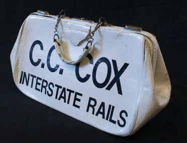
Bag, Bookmaker's bag, circa 1960s-1990s
... operations primarily during the 1920s and 1930s. After serving in the Air Force during the Second World War, Charlie entered the business during the 1940s, initially fielding at greyhound, trots and gallop meetings. In the early 1960s he moved to Melbourne, where he got his first big financial break when he was offered an interstate license to operate on the rails at all city tracks. He was a leading Melbourne bookmaker on the interstate rails racing circuit...operations primarily during the 1920s and 1930s. After serving in the Air Force during the Second World War, Charlie entered the business during the 1940s, initially fielding at greyhound, trots and gallop meetings. In the early 1960s he moved to Melbourne, where he got his first big financial break when he was offered an interstate license to operate on the rails at all city tracks. He was a leading Melbourne bookmaker on the interstate rails racing circuit ...Bags such as this one were used by bookmakers to collect and securely hold punters' bets at racing events. This bag belonged to Charlie Cox, a second-generation Australian bookmaker. His father, George Gordon Cox, ran bookmaking operations primarily during the 1920s and 1930s. After serving in the Air Force during the Second World War, Charlie entered the business during the 1940s, initially fielding at greyhound, trots and gallop meetings. In the early 1960s he moved to Melbourne, where he got his first big financial break when he was offered an interstate license to operate on the rails at all city tracks. He was a leading Melbourne bookmaker on the interstate rails racing circuit from the 1960s to the 1990s, from which period this bag originated.White painted leather bag with metal fastening mechanism. A short painted leather handle is joined to the bag by metal fastening clips.Painted on one side of the bag in black letters: "C.C. COX / INTERSTATE RAILS".bookmakers, horse racing, charlie cox, c. c. cox, interstate rails -
 Brighton Historical Society
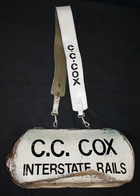
Bag, Bookmaker's bag, circa 1960s-1990s
... operations primarily during the 1920s and 1930s. After serving in the Air Force during the Second World War, Charlie entered the business during the 1940s, initially fielding at greyhound, trots and gallop meetings. In the early 1960s he moved to Melbourne, where he got his first big financial break when he was offered an interstate license to operate on the rails at all city tracks. He was a leading Melbourne bookmaker on the interstate rails racing circuit...operations primarily during the 1920s and 1930s. After serving in the Air Force during the Second World War, Charlie entered the business during the 1940s, initially fielding at greyhound, trots and gallop meetings. In the early 1960s he moved to Melbourne, where he got his first big financial break when he was offered an interstate license to operate on the rails at all city tracks. He was a leading Melbourne bookmaker on the interstate rails racing circuit ...Bags such as this one were used by bookmakers to collect and securely hold punters' bets at racing events. This bag belonged to Charlie Cox, a second-generation Australian bookmaker. His father, George Gordon Cox, ran bookmaking operations primarily during the 1920s and 1930s. After serving in the Air Force during the Second World War, Charlie entered the business during the 1940s, initially fielding at greyhound, trots and gallop meetings. In the early 1960s he moved to Melbourne, where he got his first big financial break when he was offered an interstate license to operate on the rails at all city tracks. He was a leading Melbourne bookmaker on the interstate rails racing circuit from the 1960s to the 1990s, from which period this bag originated.White painted leather bag with metal fastening mechanism. A short painted leather handle is joined to the bag by metal fastening clips. A long painted leather strap is joined to the bag by metal fastening clips.Painted on one side of the bag in black letters: "C.C. COX / INTERSTATE RAILS". "C.C. COX" is also painted in black at either end of the shoulder strap.bookmakers, horse racing, charlie cox, c. c. cox, interstate rails -
 Ballarat Tramway Museum
Document, State Electricity Commission of Victoria (SECV), SEC "Rules Governing Depot Employees", 1960s
... Document details General rules such as hours of duty, fire, accidents behaviour; Depot Operation - Safety Rules detailing many procedural rules about work safety on trams. The 5th page details rules governing track repair employees, such as safety, breaking of rail circuits and use of bitumen boilers. ...Document details General rules such as hours of duty, fire, accidents behaviour; Depot Operation - Safety Rules detailing many procedural rules about work safety on trams. The 5th page details rules governing track repair employees, such as safety, breaking of rail circuits and use of bitumen boilers. ...Set of documents - copies and originals titled 2440.1 - Copy of original document on heat sensitive photocopy foolscap size paper - Photostatted. 2440.2 - copy - from above on toner printed photocopy and reduced to A4 size - made June 2003 by Alan Bradley. 2440.3 - original copy on foolscap paper, stapled in top left hand corner - two copies held. Document details General rules such as hours of duty, fire, accidents behaviour; Depot Operation - Safety Rules detailing many procedural rules about work safety on trams. The 5th page details rules governing track repair employees, such as safety, breaking of rail circuits and use of bitumen boilers. See Also Reg Item 3705 for an earlier version. 2nd copy added 12/5/2021 - original copy. Scanned and added. 2440 - Copy of original document on heat sensitive photocopy foolscap size paper - Photostatted. 2440 - copy - copy from above on toner printed photocopy and reduced to A4 size - made June 2003 by Alan Bradley. Document details General rules such as hours of duty, fire, accidents behaviour; Depot Operation - Safety Rules detailing many procedural rules about work safety on trams. The 5th page details rules governing track repair employees, such as safety, breaking of rail circuits and use of bitumen boilers. See Also Reg Item 3705 for an earlier version. 2nd copy added 12/5/2021 - original copy. Scanned and added.Demonstrates a SECV Safety and procedures document.Photocopy and original of 'State Electricity Commission of Victoria / Ballarat Electricity Supply and Tramways / Rules Governing Depot Employees' consisting of four pages.trams, tramways, sec, safety, depot, rules, instructions -
 Ballarat Tramway Museum
Document - Instruction, State Electricity Commission of Victoria (SECV), SEC "Rules Governing Depot Employees" and "Rules Governing Track Repair Employees", 1958
... Document details General rules such as hours of duty, fire, accidents behaviour; Depot Operation - Safety Rules detailing many procedural rules about work safety on trams. The 4th page details rules governing track repair employees, such as safety, breaking of rail circuits and use of bitumen boilers. ...Document details General rules such as hours of duty, fire, accidents behaviour; Depot Operation - Safety Rules detailing many procedural rules about work safety on trams. The 4th page details rules governing track repair employees, such as safety, breaking of rail circuits and use of bitumen boilers. ...Gestetner reproduced 'State Electricity Commission of Victoria / Ballarat Electricity Supply and Tramways / Rules Governing Depot Employees' consisting of three pages and a single page "Rules Governing Track Repair Employees", with welding repair notes on the rear in pencil and ink showing location and where welds done and some dates (1958). Document details General rules such as hours of duty, fire, accidents behaviour; Depot Operation - Safety Rules detailing many procedural rules about work safety on trams. The 4th page details rules governing track repair employees, such as safety, breaking of rail circuits and use of bitumen boilers. See Also Reg Item 2440 and 2441 for copies of later versions. Was originally located with item 3692 - 1958 Trackwork diary.Yields information about the procedures, instructions and rules that tramway (depot and track) worked under in Ballarat.Four page duplicated foolscap document stapled in the top left hand corner.trams, tramways, sec, safety, depot, rules, instructions, welding -
 Vision Australia
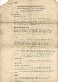
Equipment - Object, Telesensory Systems, Optacon, 1974
... Circuit Breaker protrudes from the right-hand wall inside the chassis compartment. From left to right when the back panel is facing you, are located: the jack for connecting the battery charger; the Battery Check button; the Normal-Invert switch; and the Input/Output I/O connector for use with the Visual Display, when using the Repeater Cable to connect two Optacons to one another or with other accessories. Designed not be removed from the leather case during normal operation...Circuit Breaker protrudes from the right-hand wall inside the chassis compartment. From left to right when the back panel is facing you, are located: the jack for connecting the battery charger; the Battery Check button; the Normal-Invert switch; and the Input/Output I/O connector for use with the Visual Display, when using the Repeater Cable to connect two Optacons to one another or with other accessories. Designed not be removed from the leather case during normal operation ...The Optacon OPtical-to-TActile-CONverter is a compact, portable reading aid for the blind. It is about the size of a textbook, and weighs less than 2kg. It works by converting a printed image into a tactile image that a blind person can feel with one finger. After a period of training and practice, a blind person can use the Optacon to read ordinary books, magazines, newspapers, and other printed materials. The Optacon was developed after intensive research at Standford University, California, USA and was trialed by clients of the Royal Victorian Institute for the Blind (now part of Vision Australia) in 1973. It has three main sections: 1 a miniature camera, 2 an electronics section, and 3 a tactile stimulator array. The miniature camera, about the size of a pocket knife, is mounted in a housing that has rollers for easy movement along a line of print. The camera is connected to the electronics section by a lightweight cable. The electronics section and the tactile stimulator array are in the main chassis. The array consists of 144 tiny metal rods arranged in six vertical columns and 24 horizontal rows. Each of the rods can vibrate independently. The tips of these rods protrude through holes in a concave finger plate where the index finger is placed flat in order to read. These three components act together to convert the image of a printed letter or other shape into a pattern of vibrating rods, a tactile image of the letter or shape. The letter shape is tactually perceived as an image that moves from right to left on the finger, showing the left or leading edge of the letter first. Letters are felt sequentially rather than all at once, and the image should be kept moving. The Optacon converts a printed O into a tactile form that resembles a crater with a vibrating rim -- a completed circle. C would have a gap or opening on the right side of the curve. The letter F would be felt, sequentially, as a vertical line with two trailing horizontal lines. Because it can convert any ordinary printed image into a corresponding tactile image, the Optacon is not restricted to any special typestyle or language. The camera has a zoom lens that compensates for differences in the size of type. The standard Optacon lens can accommodate type sizes from 6 point to 20 point. With the optional F4A magnifier lens, type sizes as small as 4 point can be read. Powered by a rechargeable battery, and comes with its own battery charger. The battery is contained within the main chassis, and is not removable by the user. There are four basic controls on the Optacon: the Magnification Adjustment zoom button located on the camera section on the side opposite the rollers; and the On-Off switch, the Stimulator Intensity Adjustment knob, and the Threshold Adjustment knob located on the right side of the front panel. The Circuit Breaker protrudes from the right-hand wall inside the chassis compartment. From left to right when the back panel is facing you, are located: the jack for connecting the battery charger; the Battery Check button; the Normal-Invert switch; and the Input/Output I/O connector for use with the Visual Display, when using the Repeater Cable to connect two Optacons to one another or with other accessories. Designed not be removed from the leather case during normal operation, the On-Off switch is a slide switch located on the right side of the front panel. It slides up and snaps into place in the on position. 1 black with orange front, rectangular device in leather case assistive devices, audio equipment -
 Melbourne Tram Museum
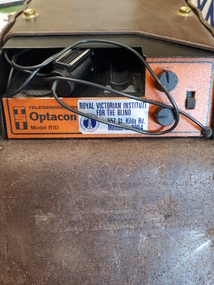
Document - Notebook, Charlie Willoughby, personal notes on tramcar maintenance, operations, recovery etc of C. Willoughby, late 1950's to early 1960's
... operations, recovery etc of C. Willoughby in a Spicers Tudor Exercise book - 64 pages with arithmetical tables on the rear cover. Topics covered: Rail Grinder - details on how to operate and maintain it North Fitzroy Dick Kerr, Clyde, K35 and RC2 Controller sequences and diagrams - notes on testing and faults Buzzer wiring diagrams Maintenance of trams interiors and rooves - items to be checked for Line Breakers Lighting Circuits Compressors Trolley poles etc Air operated doors Re-railing of Maximum Traction trams - 22E ditto for equal wheel bogies ditto when split points Use of false trucks Derailments on the Royal Park line Electrical equipment faults Adjusting Trolley Poles heights and tension Notes on truck types and braking Brake diagram summary, giving specifications and a list of relevant drawings Forms for the insulation testing of the Rail Grinders Checking motor leads and electrical equipment - written on the rear of a St Patrick's Day Procession notice for 1962. ...operations, recovery etc of C. Willoughby in a Spicers Tudor Exercise book - 64 pages with arithmetical tables on the rear cover. Topics covered: Rail Grinder - details on how to operate and maintain it North Fitzroy Dick Kerr, Clyde, K35 and RC2 Controller sequences and diagrams - notes on testing and faults Buzzer wiring diagrams Maintenance of trams interiors and rooves - items to be checked for Line Breakers Lighting Circuits Compressors Trolley poles etc Air operated doors Re-railing of Maximum Traction trams - 22E ditto for equal wheel bogies ditto when split points Use of false trucks Derailments on the Royal Park line Electrical equipment faults Adjusting Trolley Poles heights and tension Notes on truck types and braking Brake diagram summary, giving specifications and a list of relevant drawings Forms for the insulation testing of the Rail Grinders Checking motor leads and electrical equipment - written on the rear of a St Patrick's Day Procession notice for 1962. ...Exercise book with personal notes on tramcar maintenance, operations, recovery etc of C. Willoughby in a Spicers Tudor Exercise book - 64 pages with arithmetical tables on the rear cover. Topics covered: Rail Grinder - details on how to operate and maintain it North Fitzroy Dick Kerr, Clyde, K35 and RC2 Controller sequences and diagrams - notes on testing and faults Buzzer wiring diagrams Maintenance of trams interiors and rooves - items to be checked for Line Breakers Lighting Circuits Compressors Trolley poles etc Air operated doors Re-railing of Maximum Traction trams - 22E ditto for equal wheel bogies ditto when split points Use of false trucks Derailments on the Royal Park line Electrical equipment faults Adjusting Trolley Poles heights and tension Notes on truck types and braking Brake diagram summary, giving specifications and a list of relevant drawings Forms for the insulation testing of the Rail Grinders Checking motor leads and electrical equipment - written on the rear of a St Patrick's Day Procession notice for 1962. Advice from Neil Elfick, 23/6/2018 knew him when the Running Shed Foreman at Kew Depot.trams, tramways, tramcars, faults, controllers, 22e trucks, derailments, accidents, royal park, grinder, notices and information, st patricks day -
 Kiewa Valley Historical Society
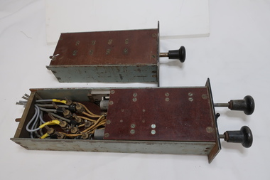
Electrical Equipment - Relays
... operation of the system. Relays protect the electrical system in 2 ways: Prevent failure or damage to electrical systems. Mitigate the effects of failure when it occurs. Switches that control other switches. Relays are used where it is necessary to control a circuit...operation of the system. Relays protect the electrical system in 2 ways: Prevent failure or damage to electrical systems. Mitigate the effects of failure when it occurs. Switches that control other switches. Relays are used where it is necessary to control a circuit ...Protective relays are one of the critical components of the elctrical power grid that serve to detect defective equipment or other dangerous or intolerable conditions and can either initiate or permit switching or simply provide an alarm to provide an alarm to provide a safer, more reliable delivery system. Used in power stations. The function of relay is to quickly remove from service any equipment that might suffer damage or otherwise affect the operation of the system. Relays protect the electrical system in 2 ways: Prevent failure or damage to electrical systems. Mitigate the effects of failure when it occurs. Switches that control other switches. Relays are used where it is necessary to control a circuit by an independent low-power signal, or where several circuits must be controlled by one signal.Used by the State Electricity Commission of Victoria for the Kiewa Hydro Electric Scheme in the power stations. Manually operated by remote control for an external circuit breaker. The relays were from a Kiewa Hydro Power Station control panel.Collection of black metal rectangular boxes (heavy) containing electrical wires forming a circuit. The longer, narrower rectangles have a bakelite knob at one end. Some of the boxes have one side of clear perspex and another has all sides of clear perspex. One is labelled "group relay". Another has windows with labels eg. 'turbine overspeed' 'emergency trip' and one has 3 steel knobs. - with 'stop', 'start'. One box is larger than the rest and has clear perspex side showing 'overcurrent relay' and workings.One has a plaque attached. Manufacture: "The English Co. Ltd. Londonpower circuits, electrical equipment, electric power control, power relays, power station, circuit breaker -
Marysville & District Historical Society
THE TRIANGLE NEWS-VOL 41 NO 42-OCTOBER 31 2014
... marysville victoria australia surprised by permaculture what's on when in october the committee of management of the gallipoli park precinct marysville community market creative triangle marysville art show 2014 party time at el kanah marysville golf report church notices 2015 goulburn river valley holiday planner mayor's chair by cr margaret rae murrindindi shire council intrepid triangle bushwalkers remembrance day services marysville & triangle community men's shed advertisements melbourne cup day office closures marysville town circuit bus marysville district football & netball club agm residential & rural real estate marysville triangle real estate dalton fiske foundation great victorian bike ride expression of interest street stall for christ church adventurous cooks triangle community dinner the outdoor education group operations shed assistant casual bus driver operations co ordinator meet the candidates for the seat of eildon pink lunch pink ribbon day national breast cancer foundation taggerty 4 seasons spring market murrindindi inc agm real estate australian sparkling wine show crossways inn live music fats wah wah marysville villains marysville & district football club new vacuum mat technology for our ambulances meet the candidates for eildon rubicon hotel motel THE TRIANGLE NEWS-VOL 41 NO 42-OCTOBER 31 2014 ...marysville, victoria, australia, surprised by permaculture, what's on when in october, the committee of management of the gallipoli park precinct, marysville community market, creative triangle, marysville art show 2014, party time at el kanah, marysville golf report, church notices, 2015 goulburn river valley holiday planner, mayor's chair by cr margaret rae, murrindindi shire council, intrepid triangle bushwalkers, remembrance day services, marysville & triangle community men's shed, advertisements, melbourne cup day office closures, marysville town circuit bus, marysville district football & netball club agm, residential & rural real estate, marysville triangle real estate, dalton fiske foundation, great victorian bike ride expression of interest, street stall for christ church, adventurous cooks, triangle community dinner, the outdoor education group, operations shed assistant, casual bus driver, operations co ordinator, meet the candidates for the seat of eildon, pink lunch, pink ribbon day, national breast cancer foundation, taggerty 4 seasons spring market, murrindindi inc agm, real estate, australian sparkling wine show, crossways inn live music fats wah wah, marysville villains, marysville & district football club, new vacuum mat technology for our ambulances, meet the candidates for eildon, rubicon hotel motel -
 Department of Energy, Environment and Climate Action
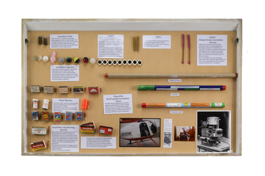
Incendiaries (various)
... Incendiaries used for planned burning operations All kind of pyrotechnics have been developed over the years from “strike anywhere” wax vestas, safety fusees, large DAIDs, burning tyres dragged behind vehicles, humble drip torches, incendiary shotguns and mortars, flame throwers of various designs, blow torches, jellied petrol blivets wired up to electrical circuits ...Department of Energy, Environment and Climate Action 71-79 Kyle Road Altona North Incendiaries used for planned burning operations All kind of pyrotechnics have been developed over the years from “strike anywhere” wax vestas, safety fusees, large DAIDs, burning tyres dragged behind vehicles, humble drip torches, incendiary shotguns and mortars, flame throwers of various designs, blow torches, jellied petrol blivets wired up to electrical circuits Forests Commission Victoria (FCV) Bushfire Planned Burning Display table that includes various type of incendiaries including windproof matches, Fusse matches, self propelled incendiary flares, incendiary capsules, vials and balls, Delayed Action Incendiary Devices (DAIDS), Gun Operated Flares (GOF) Incendiaries (various) ...Incendiaries used for planned burning operations All kind of pyrotechnics have been developed over the years from “strike anywhere” wax vestas, safety fusees, large DAIDs, burning tyres dragged behind vehicles, humble drip torches, incendiary shotguns and mortars, flame throwers of various designs, blow torches, jellied petrol blivets wired up to electrical circuits Display table that includes various type of incendiaries including windproof matches, Fusse matches, self propelled incendiary flares, incendiary capsules, vials and balls, Delayed Action Incendiary Devices (DAIDS), Gun Operated Flares (GOF)forests commission victoria (fcv), bushfire, planned burning