Showing 15 items matching "connecting rods"
-
 Moorabbin Air Museum
Book - Rotary engines, Bentley BR2 World War 1 Rotary Aero Engine
... ...Connecting rods...Rotary engine Building the quarter scale model Crankcase Crankshaft Cylinders & cylinder heads Valve gear Connecting rods Pistons Induction system Lubrication system Ignition system Propeller Technical guide for building a Bentley BR2 WW1 rotary engine, circa 1986 Bentley BR2 World War 1 Rotary Aero Engine Book Rotary engines ...Technical guide for building a Bentley BR2 WW1 rotary engine, circa 1986non-fictionTechnical guide for building a Bentley BR2 WW1 rotary engine, circa 1986building the quarter scale model, crankcase, crankshaft, cylinders & cylinder heads, valve gear, connecting rods, pistons, induction system, lubrication system, ignition system, propeller -
Moorabbin Air Museum
Manual - Griffon Engines, Maintenance Notes Griffon Mk 74 Engine ( As Fitted to Firefly Mk 4,5 & 6 Aircraft )
... Crankshaft & connecting rods...Griffon engines Crankshaft & connecting rods Pistons & rings Crankcase & reduction gear Cylinder block & camshaft assembly Sumps Wheelcase Supercharger Valve & ignition timing Oil system Auxiliary gear box Maintenance instructions for Griffon Mk 74 engine, as fitted to Firefly. ...Maintenance instructions for Griffon Mk 74 engine, as fitted to Firefly.Photocopies in blue manila walletnon-fictionMaintenance instructions for Griffon Mk 74 engine, as fitted to Firefly.crankshaft & connecting rods, pistons & rings, crankcase & reduction gear, cylinder block & camshaft assembly, sumps, wheelcase, supercharger, valve & ignition timing, oil system, auxiliary gear box -
 Kiewa Valley Historical Society
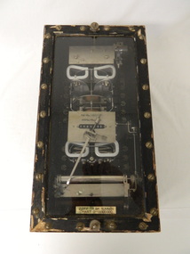
22KV Transformer Summation - S.E.C.V
... A metal cylinder is at the bottom of the instruments with a connecting rod to the 7 digit meter in the middle of the instrument panel. ...A metal cylinder is at the bottom of the instruments with a connecting rod to the 7 digit meter in the middle of the instrument panel. ...This meter belonged to the State Electricity Commission of Victoria. This meter measured the power used by all the houses in Mount Beauty and provided an inked one month period chart. This information was used to quantify and pay for the power consumption to the Transmission and Generating Department from the Distribution Department which then went on to bill local consumers.The State Electricity Commission of Victoria constructed the Kiewa Hydro Electric Scheme from the late 1930's to the 1960's. The construction towns of Bogong and Mt Beauty used electricity which was measured by this meter resulting in billing customers for the power they used.Black box with black painted wooden frame top and bottom screwed on holding clear glass at the front so that the instruments can be seen. A metal cylinder is at the bottom of the instruments with a connecting rod to the 7 digit meter in the middle of the instrument panel. In the middle of each end of the front of the box are 2 screws with knobs wound on. 22KV. BK. summation Chart 0-1 x 100,000state electricity commission of victoria. meter. transformer summation. kiewa hydro scheme. mt beauty. power. electricity. -
 National Wool Museum
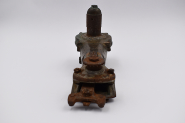
Tool - Shearing Handpiece, c.1890
... This is likely where a connecting rod to the shearing plant would be found. ...This is likely where a connecting rod to the shearing plant would be found. ...Ford and McFarlane shearing handpiece c.1890. This shearing handpiece is from ‘Wellington Lodge” in Tailem Bend, South Australia. Wellington Lodge today is an Angus beef farm; however, the property has a long history which includes wool farming. Wellington Lodge has been in the McFarlane family since the 1840’s and was originally around 19000 acres. The donor, Brian Licence, assembled this handpiece out of spare parts he found while classing wool on the property in the 1960s. Brian showed the finished handpiece to the owners once his classing work was completed and was told he could keep the handpiece as a souvenir. Brian also classed wool at “Jockwar” and “Pleasant Park” in Penola for members of the McFarlane family during the 1960s. The handpiece is named after Ford, the name of the engineer who designed the handpiece and McFarlane, the owners of Wellington Lodge Station and employers of Ford. This handpiece was developed as a prototype for use on the property. The handpiece which is made of solid brass is in a “used condition” and has been patched with solder. The handpiece is stamped with the number 10. Internally, the handpiece is powered from a drive mechanism of compressed air, this compressed air was typically produced by burning mutton fat. The handpiece comes from the pre-electrical– steam engine era of shearing. Brass metal shearing handpiece. A three-pronged fitting to hold both the comb and the blade protrudes from one end. A cylindrical stem extends vertically from the other. This is likely where a connecting rod to the shearing plant would be found. Below this vertical stem, the handpiece has an additional threaded hose fitting. This is likely where compressed air was delivered into the handpiece. The inscriptions can be found on the rear, near the previously mentioned vertical stem. Around this stem is also where the repairs of solder can be found. These repairs are unique to this handpiece and are not common practise.Etched. Base of handle. “FORD & McFARLANE . SHEEP SHEARER . Etched. Base of handle. “10”sheep shearing, shearing equipment, ford & mcfarlane, wellington lodge, tailem bend, south australia, shearing handpiece, shearing -
 Bay Steamers Maritime Museum
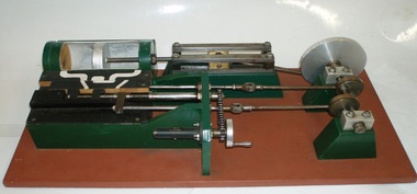
model steam engine
... From this cross-head, a connecting rod joins the piston-rod to the flywheel via the crank-pin attached to the flywheel which is part of the crankshaft. ...From this cross-head, a connecting rod joins the piston-rod to the flywheel via the crank-pin attached to the flywheel which is part of the crankshaft. ...This model was found in the collection of Bay Steamers Maritime Museum. It is not knowt who created it but it is supposed that it was constructed to educate the many masters of the Wattle in the operation of a steam engine - a not so common mode of power these days. A Bay Steamers Maritime Museum examined the model in March 2012 and discovered that is was in poor repair. Using his existing knowledge, and with reference to some historic texts, he made some repairs and returned the model to working order. Here is his anaylsis of the situation as an excerpt from the Bay Steamers Maritime Museum newsletter Steamlines May 2012 "I was confronted with a model of a steam engine used years ago as a training aid for hopeful steam engineers. Already having a knowledge of steam operations, I considered a museum write-up for that model a ‘piece of cake’. However, on turning the model’s crankshaft, the valve timing seemed ‘out of kilter’ with the movement of the piston. Problem was that the two eccentrics on the crankshaft were not properly secured to it. Eventually I fastened the two eccentrics to the crankshaft where I felt that they should be and then realized that one of them had a chain-driven valve-timing device attached. This would be adjusted while an engine was running to achieve best performance and fuel economy whilst in operation by accurately controlling the period of time during which steam under pressure from the boiler would be admitted to the cylinder and give greater time for the steam to expand in the cylinder, move the piston and turn the crankshaft and thus, drive the attached apparatus. When the valves were correctly set up it was then possible to get the model to function properly.The model comprises a green section, which is the actual the model mounted on a brown painted board. There are two parts of the model, painted white representing the steam passages, and black representing the cast- iron portions of the cylinder-block casting, and of the main valve sliding between the cylinder a second sliding valve. Of the black portions, one slides back and forth being connected to a rod which is connected to an eccentric clamped to the crankshaft and is the nearer to the flywheel of two eccentrics. This eccentric is attached to the crankshaft at an angle of 90 degrees to the crank-pin attached to the flywheel. To operate the model simply turn the flywheel by means of the handle attached to its crank-pin. A second eccentric is also attached to the crankshaft, further away from the first eccentric, and it is adjusted to operate 90 degrees from the first eccentric (that is, 180 degrees from the crank-pin) A piston (painted silver) is located in a plastic cylinder and has a piston rod which passes through one end of the cylinder, (in actual practice a steam-proof gland seals the cylinder against loss of steam) terminating in a cross-head slide between four rails guiding it. From this cross-head, a connecting rod joins the piston-rod to the flywheel via the crank-pin attached to the flywheel which is part of the crankshaft. (In actual practice, a flywheel may not be used, particularly in a multi-cylinder engine.) The white portions of the model painted nearest to the cylinder represent the two steam ports cast into the main cylinder block, whilst one section painted in between those two represents the exhaust outlet (which may be connected to a condenser to conserve water, or to the open air). The main slide valve has three white-painted portions painted thereon. It has two white-painted marks representing the steam passages to the steam ports into the cylinder, and a third section in between the other two, being that part of the valve through which exhaust steam passes in line with the ports in the cylinder block. By rotating the flywheel, the operations of an engine will be observed as steam is admitted to the main valve via the gap between the two jaws of two moveable portions of a second sliding valve which is operated by the second eccentric attached to the crank-shaft. This eccentric is used to finely tune the valve timing of this model to obtain best running results of an engine. There are various methods used for reversing a steam engine. model compound steam engine, steam engine, model, crankshaft, valve, flywheel, wattle, engineer, eccentrics -
 Flagstaff Hill Maritime Museum and Village
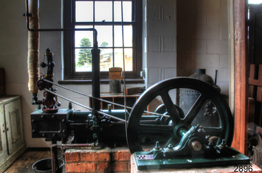
Machine - Steam Engine, Tangyes engineering, Mid-1880s
... In other words, the connecting rod is pushed by steam via the piston and piston rod and then pulled back again by steam pushing on the opposite side of the piston. ...In other words, the connecting rod is pushed by steam via the piston and piston rod and then pulled back again by steam pushing on the opposite side of the piston. ...This Tangye B-size, single-cylinder, horizontal steam engine was likely manufactured in England around the mid-1880s. It was distributed by Melbourne machinery merchants Cameron & Sutherland, which also operated in Bendigo and Ballarat. A local cheese maker once used the engine to drive factory equipment. It was later donated to the Warrnambool Technical School, which then donated it to Flagstaff Hill to add to its historical steam engine collection. Between its manufacture and its donation to Flagstaff Hill, the governor had been replaced by the current Pickering governor. This engine design was very popular in the late 19th and early 20th centuries. When connected and powered up, the engine could drive an overhead line shaft via a flat belt off its flywheel. The line shaft would then drive the machinery via flat belts. It could drive virtually any type of machinery, such as water and sewerage pumps, mine elevators, winches, cranes, metal forges, air blowers, and marine machinery. This engine features a mechanical governor, which controls the speed of the engine regardless of whether it is under load. It also has a water pump built into the valve rod, which is used to supply the boiler with water. Steam enters the cylinder via a slide valve and applies pressure to the piston; it is like a modern internal combustion engine, but in the case of the steam engine, the pressure is exerted in turn on either side of the piston. In other words, the connecting rod is pushed by steam via the piston and piston rod and then pulled back again by steam pushing on the opposite side of the piston. Thus, power is exerted almost continuously, except at the end of each piston stroke, when it reverses direction. In the 1880s, many local butter and cheese manufacturers installed Tangye steam engines to power their machinery. A comprehensive article in the Gippsland Mercury in September 1889 extolled the magnificence of the Farnham Butter Factory in Dennington, Warrnambool, and described how one Tangye engine was used to drive several machines in the cheese- and butter-making processes. A report in the Warragul Guardian in December 1890 notes that the newly opened Warrnambool Butter Factory used a Tangye steam engine to pump water from a 60-foot well. Tangye: Richard Tangye (1833–1906) and four of his brothers—James, Joseph, Edward, and George—were the sons of Joseph Tangye, a Quaker Cornish miner. In 1857, they founded the engineering firm Richard Tangye & Brothers in Birmingham, UK. In 1860, the firm became Tangye Brothers and moved to Cornwall Works in Birmingham. The business encouraged inventors to join the company and develop their patents there, as happened with Weston’s differential pulley block, invented by the Englishman Thomas Aldridge Weston in 1854. Tangye bought the patent in 1858, giving the firm the sole right to manufacture it. The design received a medal for “original application, practical utility and success” at the 1862 International Exhibition in London. Also in 1858, the Tangye firm was commissioned by Brunel’s shipping company to manufacture hydraulic lifting jacks, or rams, to launch the steamship SS Great Eastern. The success of this project brought favourable attention to the firm, and it became involved in other notable projects, including the erection of Cleopatra’s Needle in London in 1878 and work on the Forth Road Bridge in Scotland. The firm underwent several name changes over the years, including James Tangye and Brothers (1857), Tangye Brothers and Price (1859), Tangye Brothers (1860), Tangye Brothers & Holman (1876), Tangye Brothers (by 1878), Tangye Ltd. (1881), and then simply Tangye. Its machinery and equipment were exported worldwide. In 1884, a branch with showrooms, offices, and a warehouse was opened in Melbourne at Cornwall House, Collins Street West. The firm was well known for producing high-quality machinery for agriculture and industry. Even today, new Tangye machinery is available for a subsidiary of Allspeeds. An extensive account of the firm’s history, names, inventions, and further references is available in Grace’s Guide, which also includes references to and diagrams of the Tangye horizontal steam engine. The horizontal steam engine was made by the well-known engineering firm Tangye, known for its high quality of manufacture. It was an important development in machinery because it helped improve productivity. Engines of this type are still used in some parts of the world today. This engine is a good example of a late 19th-century steam engine used in industry and agriculture and adapted for many different purposes. It is also important locally because it was connected to a local cheese making business and part of the thriving western district dairy industry. It may have been one of the Tangyes engines used at the Farnham butter factory or the Warrnambool Butter Factory, which was reported to be one of the most important in the Colony. It is also connected to the Warrnambool Technical School, established in 1968. Steam engine: stationary Tangye Size B, single-cylinder, horizontal Mill type steam engine. It has a 4-inch diameter cylinder with an 8-inch stroke. The body is painted green, and the Pickering governor is red. It was manufactured in Birmingham, England, in accordance with Tangye's Patent 238930, and distributed by Cameron and Sunderland, Melbourne, in the mid-1880s. TANGEYS PATENT BIRMINGHAM B SIZE 238930 CAMERON & SUTHERLAND MELBOURNE THE PICKERING PORTLAND . GOVERNOR . CONN. U.S.A.flagstaff hill, warrnambool, maritime village, maritime museum, flagstaff hill maritime museum and village, shipwreck coast, great ocean road, machine, invention, engine, steam, steam engine, horizontal steam engine, tangyes horizontal steam engine, stationary steam engine, single cylinder steam engine, manufacturing, farming, pumps, lifting equipment, engines, machine tools, hydraulic rams, hydraulic pumps, steam pumps, differential pulleys, mill type steam engine, 4 inch cylinder, weston’s differential pulley, thomas aldridge weston, 1862 international exhibition in london, brunel, ss great eastern, cleopatra’s needle, forth road bridge, cornwall house, collins street melbourne, agricultural machinery, industrial machinery, allspeeds, dairy, pump, richard tangye & brothers, james tangye and brothers, tangye brothers and price, tangye brothers, tangye brothers & holman, tangyes ltd., tangye, richard tangye, james tangye, joseph tangye, edward tangye, george tangye, cornwall works, birmingham, pickering governor, pickering portland connecticut usa, 19th century, dairy plant, steam power, tangye's patent 238930, tangye b size engine, cameron & sutherland, machine merchants, 1880s, mid-1880s, cheese manufacturer, butter manufacturer, diary industry, warrnambool technical school, belt driven machinery, agriculture, mechanical governor, farnham butter factory, warrnambool butter factory -
 Emerald Museum & Nobelius Heritage Park
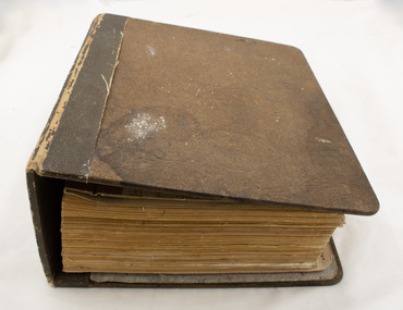
Manual - Police Manual, F. D. Atkinson, Government Printer, Victoria Police Manual, Circa 1957
... This police manual is bound as a binder, connecting upwards of 420 pages with metal rods inserted through the loose-leaf paper to form the spine. ...Atkinson, Government Printer, Melbourne" This police manual is bound as a binder, connecting upwards of 420 pages with metal rods inserted through the loose-leaf paper to form the spine. ...This copy of the 1957 Police Manual was purchased from collectibles shop in Olinda by a previous manager of the Fernlea Shop of Opportunities. Fernlea was on the site of the original Emerald Police Station, so this police manual was acquired as a relevant tie to that history. It was in turn donated to the Emerald and District Museum when the Fernlea Shop of Opportunities closed in 2025. The manual was designed as a binder such that new pages could be added if regulations were updated or amended after publication - for example, one page was inserted with greater detail on radioactive materials. The book has five sections, labelled with tabs protruding from the fore-edge: 'Regulations', 'Determinations', 'Standing Orders', 'Index', and 'List of Amendments'. The index is a short section near the end using a different paper to the rest of the book, and the List of Amendments is an unmarked table, intended to catalogue amendments to the manual. The Regulations and Determinations sections are both sizeable, containing a significant number of various guidelines, but by far the largest section is 'Standing Orders'.This police manual is bound as a binder, connecting upwards of 420 pages with metal rods inserted through the loose-leaf paper to form the spine. The outer hardcover, enclosing the book, its inner covers, and the metal binder mechanism, is brown board with leatherette spine binding. The inner cover is card with a bluje and yellow pattern decorating it; the inside of the outer cover also has a decorative pattern, in pink, blue, and white, which is peeling slightly on the front cover.non-fictionThis copy of the 1957 Police Manual was purchased from collectibles shop in Olinda by a previous manager of the Fernlea Shop of Opportunities. Fernlea was on the site of the original Emerald Police Station, so this police manual was acquired as a relevant tie to that history. It was in turn donated to the Emerald and District Museum when the Fernlea Shop of Opportunities closed in 2025. The manual was designed as a binder such that new pages could be added if regulations were updated or amended after publication - for example, one page was inserted with greater detail on radioactive materials. The book has five sections, labelled with tabs protruding from the fore-edge: 'Regulations', 'Determinations', 'Standing Orders', 'Index', and 'List of Amendments'. The index is a short section near the end using a different paper to the rest of the book, and the List of Amendments is an unmarked table, intended to catalogue amendments to the manual. The Regulations and Determinations sections are both sizeable, containing a significant number of various guidelines, but by far the largest section is 'Standing Orders'.1950s, policing -
 Flagstaff Hill Maritime Museum and Village
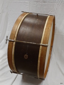
Instrument - Bass Drum, Ludwig & Ludwig, Early 1920's
... The drum is supported by a shoulder harness with a pin that connects to the eyelet incorporated on the shell of the drum, which keeps the drumheads vertical. The drum is played with one or two felt-covered drum mallets. The six tension rods...The drum is supported by a shoulder harness with a pin that connects to the eyelet incorporated on the shell of the drum, which keeps the drumheads vertical. The drum is played with one or two felt-covered drum mallets. The six tension rods ...This Marching Bass Drum is mid-size at 68 cm; these drums can range from 35 to 81 cm (14 to 32 inches). A Marching Bass Drum is slightly smaller than a Concert Base Drum and larger than a Kit or Drum Set Bass Drum. The drum is supported by a shoulder harness with a pin that connects to the eyelet incorporated on the shell of the drum, which keeps the drumheads vertical. The drum is played with one or two felt-covered drum mallets. The six tension rods connected between the drumheads can be screwed tighter or looser to change the tension of the calfskins on the drumheads, which changes their tune. This Marching base drum was made in the early 1920s by the firm Ludwig & Ludwig of Chicago, Illinois, USA. LUDWIG & LUDWIG: - William F. Ludwig was a professional drummer. He and his brother Theobold established the Ludwig & Ludwig drum factory in Chicago in 1909. They became famous for their invention of a bass drum pedal that could play faster beats on the bass drum. Theobald passed away in 1918. By 1923 Ludwig was the biggest drum manufacturer in the world. William continued on when his business was bought by C.O. Conn, but in 1937 he left to begin his own company; the WFL Drum Company. William and his son Bill purchased the Ludwig & Ludwig name back from Conn, and the name William F. Ludwig II continued on. The brand was sold to the Selmer Company and moved to Monroe, North Carolina in 1998, at the time of the 75th anniversary of the Ludwig name. Ludwig drums are still being manufactured over 100 years later. Many famous musicians and bands played the Ludwig bass drum, including Ringo Star who was the drummer in the 1960’s group The Beatles.This marching bass drum is significant for its connection to Ludwig & Ludwig, a famous and popular drum manufacturer established in 1909. The firm was once the largest drum manufacturer in the world. It is known for supplying drummers of fame, such as Ringo Star of The Beatles. This is the only drum in our collection. It is also rare, having only six tension rods, where most have from eight to twelve.Marching Bass Drum; the polished shell around the body is one continuous sheet of timber that has been steamed, shaped into a cylinder and joined together. The drumheads on the sides of the shell are strong timber strips joined into hoops that hold stretched, hand-painted white calfskin. Six Long Tube threaded nickel-plated brass tension rods are evenly spaced around the drumheads between the drumheads. A brass eyelet is fitted into the shell halfway between each drumhead, providing a connection point for the drummer’s shoulder harness. The eyelet has an indecipherable inscription. An oval brass plaque with a central formed hole has a stamped inscription. The imperial size is 27 x 13 inches. The drum was made by Ludwig and Ludwig, Chicago, Illinois, in early 1920's. On brass plaque; “LUDWIG / TRADE MARK / LUDWIG & LUDWIG / CHICAGO”flagstaff hill, warrnambool, maritime village, maritime museum, flagstaff hill maritime museum and village, shipwreck coast, great ocean road, shipwreck artefact, marching drum, bass drum, marching bass drum, pitched drum, band drum, drum mallet, marching band, military band, percussion instrument, calfskin, shoulder harness, ludwig & ludwig, wfl drum company, william f. ludwig, chicago, north carolina, the beatles, tension taps, tension rods, drum pedal, long tube tension rods -
 Flagstaff Hill Maritime Museum and Village
Accessory - Hook, ca. 1891
... connecting the Melbourne distributor to the importing of goods from the well-known German manufacturer of early domestic sewing machines, Joseph Wertheim. Flagstaff Hill Flagstaff Hill Maritime Museum and Village Warrnambool Maritime Museum Maritime Village Great Ocean Road Shipwreck Coast Wertheim sewing machine Victorian era sewing machine accessory Wertheim Sewing Machine and Hapsburg Piano Depot Wertheim Sewing Machines domestic machines dressmaking home industry fashion Hook; thin metal rod bent at one end into a curved upward arc. ...This sewing machine accessory was donated with our collection's Wertheim sewing machine accessory box. The box contains twelve accessories, the instruction book and the receipt for the purchase of a Wertheim sewing machine. The receipt was written on July 23rd 1891 by the Wertheim distributor in Melbourne, Hugo Wertheim. His business was the Wertheim Sewing Machine and Hapsburg Piano Depot, trading at 173 Williams Street, Melbourne. The purchaser was Mrs Burrowes from Burrumbeet, Victoria, a district northwest of Ballarat. She paid £6-6 (six pounds and six shillings) in cash. The receipt was signed by H. Wertheim and the other signatory looks like John A. Cherry. Hugo Wertheim (1854-1919) was an agent for his father’s cousin Joseph Wertheim, a well-established sewing machine manufacturer in Germany. He was born in Lispenhausen, Germany, and migrated to Melbourne in October 1875, where he opened a merchandising business at 39 Flinders Lane East. He returned to Germany in 1885 to marry Joseph Wertheim's daughter Sophie Emilie. The couple came back to Melbourne, and Hugo quickly established a substantial business selling sewing machines, bicycles, pianos and other mechanical devices, under brands such as Wertheim, Electra, Planet, Griffin and Hapsburg. He exhibited at agricultural shows and in 1901 at the Pan American Exposition, Buffalo, United States of America. One of his staff was O. C. Beale, who later set up his own piano business in New South Wales. Hugo continued to own 25 per cent of one of Beale's companies, which became Wertheim's Queensland business. In 1908 Hugo Wertheim opened a piano factory in Richmond, Melbourne, aiming to produce 2000 pianos and player pianos a year, predominantly using Australian materials. In laying the foundation stone, Prime Minister Alfred Deakin observed that “few men with such opportunities for a life of ease would have embarked on such an enterprise” Hugo died of chronic hepatitis in 1919 at his home in South Yarra. His eldest son, Herbert Joseph (1886-1972), continued the business. The piano factory closed in 1935, becoming a Heinz food processing plant and in 1955, GTV Channel 9 studios and offices. The Wertheim Sewing Machine Company – Joseph Wertheim (1804–1899) founded the company in 1868 in Frankfurt, Germany. At this time Joseph was the Frankfurt city delegate for the Democratic Party. At its height, the Wertheim factory employed approximately 650 workers. The company used a trademark of a dwarf holding a hammer which is known to have been used until at least 1925, however in 1909 a Star of David was also registered. In 1870 a Wertheim subsidiary was formed in Barcelona, Spain. The business imported and sold complete machines, including the English Jones machine. Locals began calling the sewing machines “las rapidas”, and the business became known as “las casa de las rapidas”. In 1915 production began of a totally manufactured Spanish Wertheim machine. Wertheim in Germany continued manufacturing machines until 1932 when the Wertheim family fled to Spain. Despite converting to Christianity from Judaism, they feared the political unrest in Germany during that time. Wertheim Spain became Rapida SA and was then the sole manufacturer of the Wertheim machines. The factory was managed by Karl Wertheim under the alias Carlos Vallin. The sewing machine accessory is part of a donation that connected to domestic life in 1891 during the Victorian era. It is significant for connecting the Melbourne distributor of Wertheim sewing machines, Hugo Wertheim, to Victoria’s northwest district where the purchaser lived. It is also significant for connecting the Melbourne distributor to the importing of goods from the well-known German manufacturer of early domestic sewing machines, Joseph Wertheim. Hook; thin metal rod bent at one end into a curved upward arc. Thais sewing machine part was made for a Wertheim sewing machine by Joseph Wertheim, Germany, and distributed by Hugo Wertheim, William Street Melbourne. Circa 1891.flagstaff hill, flagstaff hill maritime museum and village, warrnambool, maritime museum, maritime village, great ocean road, shipwreck coast, wertheim, sewing machine, victorian era, sewing machine accessory, wertheim sewing machine and hapsburg piano depot, wertheim sewing machines, domestic machines, dressmaking, home industry, fashion -
 Glenelg Shire Council Cultural Collection
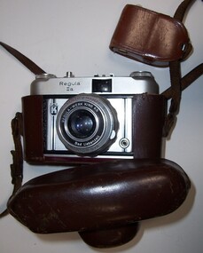
Functional object - Regula IIIa Camera with Case and Light Reader, Regula, Germany, 1956-1959
... connector on the bottom right stripe. The other common things across the range are the film advance/film counter lever, a "cold" accessory shoe, rewind knob, 1/4" tripod socket, textured leatherette and having the model name engraved on the front of the camera. The film counter on all models is on the film advance lever but has a reliability issue, it relies on a tiny rod...connector on the bottom right stripe. The other common things across the range are the film advance/film counter lever, a "cold" accessory shoe, rewind knob, 1/4" tripod socket, textured leatherette and having the model name engraved on the front of the camera. The film counter on all models is on the film advance lever but has a reliability issue, it relies on a tiny rod ...Displayed in History House. The King Regula III series were a range of 35mm viewfinder and rangefinder cameras made by King between 1956-1959. The Regula III series models all have a similar look and have a characteristic front plate. This is a flat rectangular Eloxal (ELectrolytic OXidation of ALuminum) plate, with distinctive chrome-black-chrome stripes each side. The King logo is at the top of the left-hand stripe, and a PC flash sync connector on the bottom right stripe. The other common things across the range are the film advance/film counter lever, a "cold" accessory shoe, rewind knob, 1/4" tripod socket, textured leatherette and having the model name engraved on the front of the camera. The film counter on all models is on the film advance lever but has a reliability issue, it relies on a tiny rod in the film advance lever, and a fixed rod on the camera body pushing against each other every time the lever is advanced; the problem is the rods are so small that they wear down with repeated use until the film counter stops working.Regula IIIa Camera Regula IIIa is a basic viewfinder camera with a Prontor-SVS shutter, but no focus aids, light meter, frame lines in the viewfinder or strap lugs on the body. 367.1 - Single lens reflex camera. 367.2 - Light metre in leather case. 367.3 - Brown leather case.Front: Regula-werk king KG/Bad Liebenzell/Prontor - SVS (on lens) Regula/IIIa (on body)camera, photography -
 Flagstaff Hill Maritime Museum and Village
Machine - Steering Gear, 1889
... connect the rudder to the ship's wheel, often housed in a box-like construction behind the helm. The rudder was, in turn, mounted on a pintle or stern-post held in place by gudgeon's (sockets). The steering was activated with lines attached to the blocks on the two threads (half left hand, half right hand) of the steering gear. As the helmsman turned the helm in the direction in which he wished the ship to travel, the central screw of the steering gear, which was attached to the back of the helm, turned horizontally. This caused the rods...connect the rudder to the ship's wheel, often housed in a box-like construction behind the helm. The rudder was, in turn, mounted on a pintle or stern-post held in place by gudgeon's (sockets). The steering was activated with lines attached to the blocks on the two threads (half left hand, half right hand) of the steering gear. As the helmsman turned the helm in the direction in which he wished the ship to travel, the central screw of the steering gear, which was attached to the back of the helm, turned horizontally. This caused the rods ...Steering Gear Operation: All steering was done from the stern of the ship and a steering mechanism was used to connect the rudder to the ship's wheel, often housed in a box-like construction behind the helm. The rudder was, in turn, mounted on a pintle or stern-post held in place by gudgeon's (sockets). The steering was activated with lines attached to the blocks on the two threads (half left hand, half right hand) of the steering gear. As the helmsman turned the helm in the direction in which he wished the ship to travel, the central screw of the steering gear, which was attached to the back of the helm, turned horizontally. This caused the rods on either side of the gear to move backwards or forwards at the same time, which then turned the pintle and rudder to port or starboard. A brief history of the Newfield (1889-1892): - The Newfield was an iron and steel sailing barque of 1306 tons, built in 1889 by Alexander Stephen & Sons Dundee (Yard No 89) for Brownelles & Co., Liverpool. The Newfield was on a voyage from Sharpness to Brisbane on 29 August 1892, with a cargo of 1850 tons of fine rock salt. The Cape Otway light had been sighted in squally, bumpy weather, but the captain was under the impression it was the King Island light. The ship’s chronometers were wrong, and orders were given to tack the ship away from the light, which headed it straight for the cliffs of the Victorian coast. The vessel struck rocks about 100 yards from shore, and five feet of water immediately filled the holds. The captain gave orders to lower the boats which caused a disorganised scramble for safety among the crew. The panic resulted in the deaths of nine men, including the captain when they drowned after the boats capsized in heavy seas. The seventeen men who regained the ship decided to wait until daylight and rowed to Peterborough in the ship’s jolly boat and gig after locals had failed to secure a rocket apparatus line to the ship. The Marine Board inquiry found the wreck was caused by a "one-man style of navigation" and that the captain had not heeded the advice of his crew.The Newfield wreck and its collection of recovered items are heritage listed and are regarded as historically significant. They represent aspects of Victoria’s shipping history and their potential for us today to interpret the maritime history and social themes of the time. The assemblage of various Newfield artefacts held in the Flagstaff Hill Museum is not only significant for its association with the shipwreck but helps archaeologists when examining the relationship between the objects to better understand our colonial marine past.Ship’s steering gear, cast iron, consists of a long round metal rod into which gears have been machined. The thread of the gear from one end to almost the centre winds in a left hand direction while the thread of the gear from the other end to almost the centre winds in the right hand direction. Each end of the rod has a metal coupler attached and two narrower round rods are also attached to the coupling, one each side of the gear rod, the same length as it and parallel to it. Two more ‘S’ shaped couplers are joined to the gear rod. Each of these have an opening through which the gear rod is threaded and can move along. There is another opening in these couplers through which one of the narrower rods is threaded. The other end of this coupler has half length metal rod attached to it by a bolt through the ring at the end of the rod. One end of the steering gear still has the brass hub of the ship’s wheel solidly attached. The hub no longer has its wooden spokes but the ten holes for the spokes can be easily recognised.Noneflagstaff hill, maritime museum, shipwreck coast, warrnambool, peter carmody, carmody, newfield, shipwreck, peterborough, south west victoria, rocket, rocket crew, shipwreck artefact, flagstaff hil maritime museum, steering, steering gear, screw steering gear, sailing ship -
 Flagstaff Hill Maritime Museum and Village
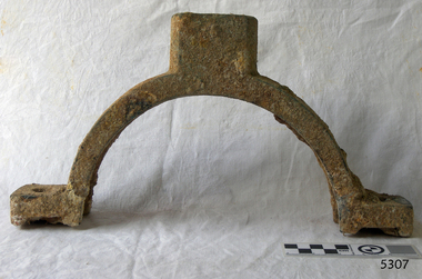
Bearing cap, (estimated); Before The Newfield completion in 1889
... The bearing cap could have been used on the donkey engine to hold the rod of the winch gear wheel in place, or bolted to another bearing cap around the neck on the top of the boiler’s cylinder, connecting it to the flue. ...The bearing cap could have been used on the donkey engine to hold the rod of the winch gear wheel in place, or bolted to another bearing cap around the neck on the top of the boiler’s cylinder, connecting it to the flue. ...This bearing cap is thought to be from a donkey winch engine, (or steam donkey, or donkey winch), which is a small secondary steam engine with a cylindrical shaped boiler. In 19th century merchant sailing a steam donkey was often used in marine applications such as to help raise and lower larger sails, load and unload cargo or to power pumps. The bearing cap could have been used on the donkey engine to hold the rod of the winch gear wheel in place, or bolted to another bearing cap around the neck on the top of the boiler’s cylinder, connecting it to the flue. The Newfield was a three-masted iron and steel barque, built in Dundee, Scotland, in 1889 by Alexander Stephen and Sons. It was owned by the Newfield Ship Company in 1890 and later that year It was registered in Liverpool to owners Brownells and Co. The Newfield left Sharpness, Scotland, on 28th May 1892 with a crew of 25 under the command of Captain George Scott and on 1st June left Liverpool. She was bound for Brisbane, Australia, with a cargo of 1850 tons of fine rock salt, the main export product of Sharpness. At about 9pm on 28th August 1892, in heavy weather, Captain Scott sighted, between heavy squalls, the Cape Otway light on the mainland of Victoria but, due to a navigational error (the ship’s chronometers were wrong), he assumed it to be the Cape Wickham light on King Island, some 40 miles south. He altered his course to the north, expecting to enter Bass Strait. The ship was now heading straight for the south west Victorian coast. At about 1:30am the Newfield ran aground on a reef about 100 yards from shore and one mile east of Curdie’s Inlet, Peterborough. The ship struck heavily three times before grounding on an inner shoal with 6 feet of water in the holds. Rough sea made the job of launching lifeboats very difficult. The first two lifeboats launched by the crew were smashed against the side of the ship and some men were crushed or swept away. The third lifeboat brought eight men to shore. It capsized when the crew tried to return it to the ship for further rescue The rescue was a difficult operation. The Port Campbell Rocket Crew arrived and fired four rocket lines, none of which connected with the ship. Peter Carmody, a local man, volunteered to swim about one mile off shore to the ship with a line to guide the fourth and final lifeboat safely to shore. He was assisted by James McKenzie and Gerard Irvine. Seventeen men survived the shipwreck but the captain and eight of his crew perished. The Newfield remained upright on the reef with sails set for a considerable time as the wind slowly ripped the canvas to shreds and the sea battered the hull to pieces. The Marine Board inquiry found the wreck was caused by a "one man style of navigation" and that the Captain had not heeded the advice of his crew. According to Jack Loney ‘… when the drama was over . . the Newfield was deserted except for the Captain’s dog and two pigs.’ Peter Carmody was awarded the Bramley-Moore medal by the Liverpool Shipwreck and Humane Society for Saving Life at Ssea, which he received by mail on January 21st 1893. The medal and a letter of congratulations were donated to Flagstaff Hill Maritime Museum by Peter Carmody’s grand-daughter Norma Bracken and her son Stuart Bracken on 25th May 2006. The Bearing Cap joins other items in the Newfield collection.Flagstaff Hill’s collection of artefacts from the Newfield is significant for its association with the shipwreck Newfield, which is listed on the Victorian Heritage Registry. The collection is significant because of the relationship between the objects. The Newfield collection is archaeologically significant as the remains of an international cargo ship. The Newfield collection is historically significant for representing aspects of Victoria’s shipping history and its association with the shipwreck.Brass bearing cap from the wreck of the sailing ship “Newfield” is possibly from a donkey winch engine. The half-circle shaped cuff with a rectangular brass block attached to the outside of each end of the half-circle. Both blocks have a round hole in their centre and are approximately the same depth and width as the cuff. Midway around the half-circle cuff is another brass block that is about twice the depth of the cuff. It appears to have been a circular shape that has been modified to match the width of the collar, having had the sides of the circle cut off to leave straights edge parallel to the edges of the cuff. In the centre of this block is another hole, and there appears to be the head of a bolt inside this hole. The bearing cap is lightly encrusted.1893, flagstaff hill, flagstaff hill maritime museum, maritime museum, warrnambool, newfield, 1892, 28 august 1892, port campbell, shipwreck, nineteenth century, ship, curdie s river, victorian shipwrecks, barque, ship wreck, 29 august 1892, 19th century, bearing cap, donkey engine, donkey winch, steam donkey -
 Alfred Hospital Nurses League - Nursing History Collection
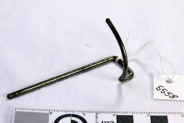
Functional object - Medical Equipment - proctoscope, unknown
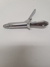
... connects to the body of the proctoscope. Part two is the obturator, which has an olivary tip, and handle (four sided) connected by narrow rod...connects to the body of the proctoscope. Part two is the obturator, which has an olivary tip, and handle (four sided) connected by narrow rod Functional object Medical Equipment - proctoscope ...A proctoscope was used in wards/outpatient or emergency department for examination of the anus and rectum Of significance to the AHNL as nurses were involved in the preparation of equipment and patient.Consist of two parts, both made of siler coloured metal. Part one is the speculum, flared at one end and has an angled handle, with a small inlet that connects to the body of the proctoscope. Part two is the obturator, which has an olivary tip, and handle (four sided) connected by narrow rodmade in England stamped on one side of handle of speculum at base, previous catalogue number written in black ink. ward 12 No 6. engraved on other side of handle.' On one face of obturator handle Alfred Hospital is engraved. on second face Wd22/23 is engraved, on third face a letter T is engraved, on the fourth face is a scratched out engraving and the letter T. The old catalogue number is written in permanent black in on this fourth face. medical equipment, proctoscope, medical procedures -
 Vision Australia
Photograph - Image, Operating a switchboard
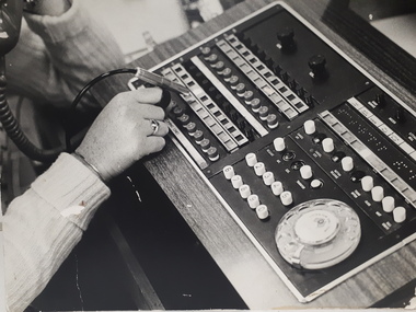
... connecting outside callers to internal lines. The switchboard has a series of buttons with printed labels and some with Braille underneath them. On the operator's forefinger is a silver metal rod...connecting outside callers to internal lines. The switchboard has a series of buttons with printed labels and some with Braille underneath them. On the operator's forefinger is a silver metal rod ...A female hand operates a switchboard, connecting outside callers to internal lines. The switchboard has a series of buttons with printed labels and some with Braille underneath them. On the operator's forefinger is a silver metal rod, probably used to depress the switches. To the bottom right of the image are both buttons with individual numbers as well as a rotary dial. In the background, her arm rests on the bench as she listens to the handset.Digital image of female using a switchboardemployment -
 Ballarat Tramway Museum
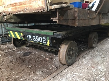
Vehicle - Four Wheel Flat top Trolley, Commonwealth Railways - Port Augusta Workshops (Understood), 1940's?
... Metal tie rods in front over axles and metal has connecting tow/couplers. ...Metal tie rods in front over axles and metal has connecting tow/couplers. ...Four wheel flat top track trolley- deck wood frame and sides on four fabricated/pressed wheels, with bearings, axles- Used to transport materials- hand pushed or towed. Metal tie rods in front over axles and metal has connecting tow/couplers. Relocated to Bungaree c2015 when 22 moved. Photographed at Bungaree 6-4-2020 by Neville Britton, see image btm18i1.jpg. Record updated 6-4-2020. See detailed information on back of sheet in folder for sketches, timber damaged, notes re a number plate and a note regarding work done 7/97 in replacing underside diagonal bracing supports.On underside in paint, "To Cargeeg, 50 Pasadena East Bentleigh, Melbourne"trams, tramways, commonwealth railways, maintenance equipment, railway trolley