Showing 79 items matching "control system operation"
-
 Melbourne Tram Museum
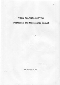
Document - Instruction Book, B. Manser Pty Ltd, "Tram Control System - Operation and Maintenance Manual", 2003
... "Tram Control System - Operation and Maintenance Manual"...Instruction Book - 20 pages contained with a clear plastic cover and black retaining block or strip, titled "Tram Control System - Operation and Maintenance Manual", giving details of the system to control tramcars within depots, which tracks, timetables, dispatching, computer system, caters for run-ins, varying lengths and other criteria. ...Manser Pty Ltd 2003 on front cover. "Tram Control System - Operation and Maintenance Manual" Document Instruction Book B. ...Instruction Book - 20 pages contained with a clear plastic cover and black retaining block or strip, titled "Tram Control System - Operation and Maintenance Manual", giving details of the system to control tramcars within depots, which tracks, timetables, dispatching, computer system, caters for run-ins, varying lengths and other criteria. Has copyright - B. Manser Pty Ltd 2003 on front cover.trams, tramways, depots, depot trackwork, tramcars, instructions, depot starter, software -
 Moorabbin Air Museum
Manual (Item) - Astra Israel Aircraft Industries Flight Control System Description and Operation FCS-80
... Astra Israel Aircraft Industries Flight Control System Description and Operation FCS-80...Astra Israel Aircraft Industries Flight Control System Description and Operation FCS-80...Moorabbin Air Museum Moorabbin Airport 12 First Street Moorabbin melbourne Astra Israel Aircraft Industries Flight Control System Description and Operation FCS-80 Manual Astra Israel Aircraft Industries Flight Control System Description and Operation FCS-80 ... -
Moorabbin Air Museum
Manual - Boeing 747 APU, GTCP 660-4 747 APU
... system...Control electrical/electronic turbine systems...Control system operation...Moorabbin Air Museum Moorabbin Airport 12 First Street Moorabbin melbourne Boeing 747 APU Installation & specifications Basic function & construction Lubrication system Fuel system components Bleed air system Control electrical/electronic turbine systems Control system operation Indicating systems Trouble shooting Installation & maintenance of Boeing 747 GTCP 660-4 auxiliary power unit ( APU ) , circa 1970 Loose pages stapled top left hand corner GTCP 660-4 747 APU Manual Boeing 747 APU ...Installation & maintenance of Boeing 747 GTCP 660-4 auxiliary power unit ( APU ) , circa 1970Loose pages stapled top left hand cornernon-fictionInstallation & maintenance of Boeing 747 GTCP 660-4 auxiliary power unit ( APU ) , circa 1970installation & specifications, basic function & construction, lubrication system, fuel system components, bleed air system, control electrical/electronic turbine systems, control system operation, indicating systems, trouble shooting -
Moorabbin Air Museum
Manual - Lockheed Hercules technical training, Customer Training Power Plant APU Supplement
... ...Load control system....Operation...Moorabbin Air Museum Moorabbin Airport 12 First Street Moorabbin melbourne Lockheed Hercules technical training APU - general Gas turbine operating Electrical controls Functions Airflow path Lubrication system Fuel system Load control system .Operation/inspection/maintenance Technical overview of Hercules auxiliary power unit, circa 1976 Customer Training Power Plant APU Supplement Manual Lockheed Hercules technical training ...Technical overview of Hercules auxiliary power unit, circa 1976non-fictionTechnical overview of Hercules auxiliary power unit, circa 1976apu - general, gas turbine operating, electrical controls, functions, airflow path, lubrication system, fuel system, load control system, .operation/inspection/maintenance -
 Melbourne Tram Museum
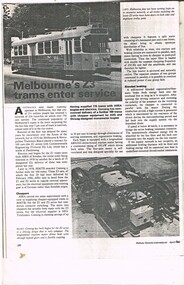
Document - Photocopy, Railway Gazette International, "Melbourne's Z3 trams enter service", c1980
... Photocopy, two foolscap sheets, stapled in top left hand corner, of an article that appeared in the April 1980 issue of Railway Gazette International, pages 286 - 287, titled "Melbourne's Z3 trams enter service", giving details of the Z3 class trams, its control systems, construction, operation, braking, bogies and suppliers. ...Melbourne Tram Museum 8 Wallen Road Hawthorn melbourne Trams tramways Z3 class New Trams Comeng Duwag Assembly ASEA Photocopy, two foolscap sheets, stapled in top left hand corner, of an article that appeared in the April 1980 issue of Railway Gazette International, pages 286 - 287, titled "Melbourne's Z3 trams enter service", giving details of the Z3 class trams, its control systems, construction, operation, braking, bogies and suppliers. ...Photocopy, two foolscap sheets, stapled in top left hand corner, of an article that appeared in the April 1980 issue of Railway Gazette International, pages 286 - 287, titled "Melbourne's Z3 trams enter service", giving details of the Z3 class trams, its control systems, construction, operation, braking, bogies and suppliers. Also has an article on the Frankfurt U3 metro cars.trams, tramways, z3 class, new trams, comeng, duwag, assembly, asea -
 Bendigo Military Museum
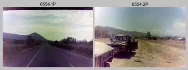
Photograph - RA Svy Project C4 Aerodist Operation, Eastern Arnhem Land, NT, 1967
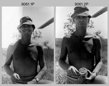
... operations for 12 years from 1964 to 1975. Aerodist MRC2 was a tellurometer-based system adapted for aircraft to accurately measure distances between non-intervisible ground survey stations, using the aircraft as an intermediate station. Lower order geodetic results could be achieved by survey network trilateration. The measured distances between stations formed survey networks from which each station’s latitude and longitude was computed. Aerodist MRC2 was RA Svy’s major horizontal control...operations for 12 years from 1964 to 1975. Aerodist MRC2 was a tellurometer-based system adapted for aircraft to accurately measure distances between non-intervisible ground survey stations, using the aircraft as an intermediate station. Lower order geodetic results could be achieved by survey network trilateration. The measured distances between stations formed survey networks from which each station’s latitude and longitude was computed. Aerodist MRC2 was RA Svy’s major horizontal control ...This is a set of 30 photographs of Royal Australian Survey Corps (RA Svy) personnel from Central Comd Fd Svy Unit (Adelaide) on Aerodist survey operation - Project C4 in Eastern Arnhem Land, Northern Territory in 1967. Photos of personnel were taken either at the operations base at Numbulwar or the main base at Gove (Nhulunbuy). RA Svy conducted nineteen Aerodist operations for 12 years from 1964 to 1975. Aerodist MRC2 was a tellurometer-based system adapted for aircraft to accurately measure distances between non-intervisible ground survey stations, using the aircraft as an intermediate station. Lower order geodetic results could be achieved by survey network trilateration. The measured distances between stations formed survey networks from which each station’s latitude and longitude was computed. Aerodist MRC2 was RA Svy’s major horizontal control survey tool for mainly medium scale topographic mapping (scale 1:100,000 Class A being spatially accurate to within 50 metres) in PNG, northern NT, north-west WA, Kalimantan Barat (West) Indonesia, Sumatra Indonesia, Gulf of Carpentaria and Cape York, QLD. In 1967, the Aerodist MRC2 Master equipment was installed in the aircraft featured in this set of photos, Executive Air Services’ (Essendon VIC) Grand Aero Commander VH-EXX. It was the same aircraft type and company contracted to Division of National Mapping for Aerodist MRC2 surveys. From July to October 1967 the aircraft was attached to Central Comd Fd Svy Unit (Adelaide - Major Don Ridge) on Project C4 eastern-Arnhem Land NT, where 317 Aerodist lines measuring 17,300 line miles were successfully completed. This was the most productive Aerodist project thus far. The most common helicopter used by RA Svy up to 1972 was the civilian Bell 47G-2 and the Sioux Light Observation Helicopters (LOH), the Australian Army’s equivalent featured in this photo set. These light observation helicopters had a limiting load carrying capacity of up to about 500 pounds. By comparison, one Aerodist team including two people weighed up to 1,500 pounds. Source: Royal Australian Survey Corps – Aerodist Years 1964-1975 by Peter Jensen. Refer to Item 9061.26P for more photos taken during this Aerodist survey operation.This is a set of 30 photographs of Royal Australian Survey Corps (RA Svy) personnel on Aerodist survey operations in Eastern Arnhem Land, Northern Territory in 1967. The photographs are on 35mm negative film and scanned at 96 dpi. They are part of the Army Survey Regiment’s Collection. .1) to .4) - black & white, 20th August 1967, Project C4 Aerodist Operations Base - Numbulwar, NT. .5) - Photo, black & white, 1967. Probable wrecked Indonesian fishing vessel. .6) to .8) - Photo, black & white, 1967. Unidentified survey operations base, L to R: unidentified personnel. .9) - Photo, black & white, 1967. Unidentified survey operations base, unidentified soldier driving a Haflinger 4x4 Light utility vehicle. .10) - Photo, black & white, 1967. Unidentified survey operations base, L to R: unidentified technician. .11) - Unidentified technician reading two survey altimeters to compute corrections to the measured distances for atmospheric refraction and to compute the sea level distances from the slope distances aircraft to the ground stations. .12) - Photo, black & white, 1967. Survey operations base, L to R: unidentified (x3), W01 Pat Wood BEM, unidentified. .13) to .16) - Photo, black & white, 1967. Unidentified personnel operating remote Aerodist MRC2 ground instruments. .17) to .18) - Photo, black & white, 1967. Unknown RA Svy office location. .19) to .20) - Photo, black & white, 1967. Aerodist MRC2 Master equipment. .21) to .22) - Photo, black & white, 1967. Aero Commander VH-EXX probably at Gove, NT, Central Comd Fd Svy Unit (Adelaide) – OC Major Don Ridge. .23) to .25) - Photo, black & white, 1967. Aero Commander VH-EXX probably at Gove, NT. Unidentified personnel. .26) - Photo, black & white, 1967. Aero Commander VH-EXX probably at Gove, NT. Aerodist antenna pods are visible on the aircraft. .27) to .29) - Photo, black & white, 1967. Australian Army Sioux Light Observation Helicopter (LOH) probably at Gove, NT. .30) - Photo, black & white, 1967. Panelled U337 survey station, visible as a white cross on aerial identification photo..1P to .2P – date and location on edge of film negative. .5P to .28P – no annotations .29P - annotated in white ‘RW-JEP Gove NT’ .30P - annotated in white ‘U337 Spool No1 Jun67’royal australian survey corps, rasvy, army survey regiment, army svy regt, fortuna, asr, aerodist, surveying, central comd fd svy unit -
 Bendigo Military Museum
Administrative record - Joint Committee for the exchange of Information on ADP within the RASvy Corps, Activities Jun- Dec 1985, Army Survey Regiment, December 1985
... operation of the Royal Australian Survey Corps Mapping capability and production. This paper describes elements of the ADP with a comprehensive description of each. They Include, PDP 11/70 Memory, Map Stock Control System...operation of the Royal Australian Survey Corps Mapping capability and production. This paper describes elements of the ADP with a comprehensive description of each. They Include, PDP 11/70 Memory, Map Stock Control System ...Automated Computer Processing (ADP) was instrumental to the successful operation of the Royal Australian Survey Corps Mapping capability and production. This paper describes elements of the ADP with a comprehensive description of each. They Include, PDP 11/70 Memory, Map Stock Control System, Digital Terrain Elevation Data, Digital Terrain Model Package, ASMAPS, ASTIS, Reflectance Hill Shading, Aerial Triangulation and Terrain Analysis.Two page paper report about Automated Data Processing, unstapledHand annotated "Folio 74" in top right hand cornerroyal australian survey corps, rasvy, fortuna, army survey regiment, army svy regt, asr -
 Bendigo Military Museum
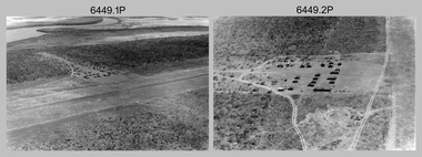
Photograph - RA Svy Project C4 Aerodist Operation, Eastern & Western Arnhem Land, NT, 1967, 1968
... In 1968, after completion of the Kimberley Aerodist Operation project, the Aerodist system in VH-EXX was immediately deployed to western-Arnhem Land NT for Central Comd Fd Svy Unit (Adelaide - Major Don Ridge) to complete the mapping control across northern NT from mid-July to October. ...In 1968, after completion of the Kimberley Aerodist Operation project, the Aerodist system in VH-EXX was immediately deployed to western-Arnhem Land NT for Central Comd Fd Svy Unit (Adelaide - Major Don Ridge) to complete the mapping control across northern NT from mid-July to October. ...This is a set of 26 photographs of Royal Australian Survey Corps (RA Svy) personnel from Central Comd Fd Svy Unit (Adelaide) on Aerodist survey operation - Project C4 in Eastern Arnhem Land, Northern Territory in 1967 (photos .4P to .26P) and in Western Arnhem Land, Northern Territory in 1968 (photos .1P to .3P). Photos of personnel were taken either at the operations base at Numbulwar or the main base at Gove (Nhulunbuy). RA Svy conducted nineteen Aerodist operations for 12 years from 1964 to 1975. Aerodist MRC2 was a tellurometer-based system adapted for aircraft to accurately measure distances between non-intervisible ground survey stations, using the aircraft as an intermediate station. Lower order geodetic results could be achieved by survey network trilateration. The measured distances between stations formed survey networks from which each station’s latitude and longitude was computed. Aerodist MRC2 was RA Svy’s major horizontal control survey tool for mainly medium scale topographic mapping (scale 1:100,000 Class A being spatially accurate to within 50 metres) in PNG, northern NT, north-west WA, Kalimantan Barat (West) Indonesia, Sumatra Indonesia, Gulf of Carpentaria and Cape York, QLD. In 1967, the Aerodist MRC2 Master equipment was installed in the aircraft featured in this set of photos, Executive Air Services’ (Essendon VIC) Grand Aero Commander VH-EXX. It was the same aircraft type and company contracted to Division of National Mapping for Aerodist MRC2 surveys. From July to October 1967 the aircraft was attached to Central Comd Fd Svy Unit (Adelaide - Major Don Ridge) on Project C4 eastern-Arnhem Land NT, where 317 Aerodist lines measuring 17,300 line miles were successfully completed. This was the most productive Aerodist project thus far. The most common helicopter used by RA Svy up to 1972 was the civilian Bell 47G-2 and the Sioux Light Observation Helicopters (LOH), the Australian Army’s equivalent featured in this photo set. These light observation helicopters had a limiting load carrying capacity of up to about 500 pounds. By comparison, one Aerodist team including two people weighed up to 1,500 pounds. In 1968, after completion of the Kimberley Aerodist Operation project, the Aerodist system in VH-EXX was immediately deployed to western-Arnhem Land NT for Central Comd Fd Svy Unit (Adelaide - Major Don Ridge) to complete the mapping control across northern NT from mid-July to October. The Aerodist MRC2 Remote antenna seen in Photos .24P to .26P is mounted on a 20 foot pole tower. The antenna direction was controlled by wires/ropes to the two arms under the dish at right angles. The antenna elevation could be changed to the vertical for aircraft height checks as seen in photo .25P. Source: Royal Australian Survey Corps – Aerodist Years 1964-1975 by Peter Jensen. Refer to Item 6449.30P for more photos taken during these Aerodist survey operations.This is a set of 26 photographs of Royal Australian Survey Corps (RA Svy) personnel on Aerodist survey operations in Eastern Arnhem Land, Northern Territory in 1967 and Western Arnhem Land, Northern Territory in 1968. The photographs are on 35mm negative film and scanned at 96 dpi. They are part of the Army Survey Regiment’s Collection. .1) to .2) – Photo, black & white, 1968, unidentified soldier with an opened can of food, possibly bully beef. .3) – Photo, black & white, 15 Aug 1968, aerial view of terrain taken from a helicopter in vicinity of MILINGIMBI SIERRA. .4) – Photo, black & white, 1967, aerial view of an island taken from a helicopter. .5) & .6) – Photo, black & white, 1967, unidentified soldier driving a Haflinger 4x4 Light utility vehicle with trailer. .7) – Photo, black & white, 1967, unidentified surveyors taking vertical measurements with a leveling instrument and staff. .8) – Photo, black & white, 1967, Australian Army Sioux Light Observation Helicopter (LOH) with float removed. .9) to .11) – Photo, black & white, 1967, Australian Army Sioux Light Observation Helicopter (LOH) with floats. .12) – Photo, black & white, 1967, civilian Bell 47G-2 helicopter (Australian Army Sioux LOH equivalent) refuelled. .13) – Photo, black & white, 1967, survey station on coastline surrounded by white plastic aerial photographic identification panels lined with rocks. .14) & .15) – Photo, black & white, 1967, soldier (possibly a signaller from RA Sigs) operating a radio. .16) – Photo, black & white, 1967, Central Comd Fd Svy Unit Operations Section tent, Main Base Gove (Nhulunbuy) L to R: SPR Harry Dunn, WO1 Pat Wood BEM. .17) – Photo, black & white, 1967, Central Comd Fd Svy Unit Operations Section tent, Main Base Gove (Nhulunbuy) L to R: unidentified, WO1 Pat Wood BEM. .18) – Photo, black & white, 1967, Central Comd Fd Svy Unit Operations Section, Main Base Gove (Nhulunbuy), unidentified Australian Army Catering Corps cook preparing meals. .19) – Photo, black & white, 1967, Central Comd Fd Svy Unit Operations Section, Main Base Gove (Nhulunbuy) mess tent in readiness for meals. .20) – Photo, black & white, 1967, Bank of batteries in transit boxes undergoing recharging using generators. .21) – Photo, black & white, 1967, A topographic survey identification plaque set in a concrete block being weighed using a set of scales hanging from slaughtering gallows. .22) – Photo, black & white, 1967, CPL (Geoff or Gary) Larkin operating the remote Aerodist MRC2 ground instrument at Veronica Island, located north of Nhulunbuy. .23) – Photo, black & white, 1967, L to R: CPL (Geoff or Gary) Larkin with unidentified surveyor operate the remote Aerodist MRC2 ground instrument at Venica Island, located north of Nhulunbuy. .24) & .25 – Photo, black & white, 1967, The Aerodist MRC2 Remote antenna. .26) – Photo, black & white, 1967, The Aerodist MRC2 Remote antenna.The following photos are annotated in black ink on edge of film negative: .3P – ’15 Aug ’68, 2000’, 1-C18 ’68 MILINGIMBI SIERRA’ .4P – ’U462’ .8P – ‘1-C3/67 Float Removed’ .13P – ‘U477 10-C3/67 .20P - ‘2-C3/67 Bank of Chargers’ .21P - ‘3-C3/67 Gallows & Scales’ .22P - ‘0462 VERONICA ISLAND NT, CPL Larkin’ .23P - ‘0462 VERONICA ISLAND NT’ .24P - ‘4-C3/67 20’ Aerodist Tower’ .25P - ‘5-C3/67 20’ Aerodist Tower’ .26P - ‘6-C3/67 20’ Aerodist Tower’royal australian survey corps, rasvy, army survey regiment, army svy regt, fortuna, asr, aerodist, surveying, central comd fd svy unit -
 Kiewa Valley Historical Society
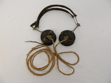
Headphones - Transmitter radio, c1924
... controls in an unusual system of radio telephone providing communication. At the time it was unique in Australia and installed by the S.E.C.V. technicians. It provided an unattended shortwave radio link between two ordinary telephone switchboards, connecting any of the S.E.C.V.'s internal lines with the telephone system at Bogong and the construction camps beyond. From Bogong, radio phones connect to the outpost stations on the High Plains far above the snow-line. In operation...controls in an unusual system of radio telephone providing communication. At the time it was unique in Australia and installed by the S.E.C.V. technicians. It provided an unattended shortwave radio link between two ordinary telephone switchboards, connecting any of the S.E.C.V.'s internal lines with the telephone system at Bogong and the construction camps beyond. From Bogong, radio phones connect to the outpost stations on the High Plains far above the snow-line. In operation ...Radio Telephone was minuted during the war. It was approved in 1944 for State Electricity Commission of Victoria use only. It was completed by the end of 1946. Used by the State Electricity Commission of Victoria at Bogong during the construction of the Kiewa Hydro Electric Scheme to connect with head office in Melbourne. It allows one conversation at a time using traffic controls in an unusual system of radio telephone providing communication. At the time it was unique in Australia and installed by the S.E.C.V. technicians. It provided an unattended shortwave radio link between two ordinary telephone switchboards, connecting any of the S.E.C.V.'s internal lines with the telephone system at Bogong and the construction camps beyond. From Bogong, radio phones connect to the outpost stations on the High Plains far above the snow-line. In operation, the service is similar to a normal telephone system but dispenses with the physical connection of wires and poles between the main terminals. Historical: This type of headphone was recommended for amateurs. It may have been used by operators on the Switchboard at Bogong or one of the construction camps on the Kiewa Hydro Electric Scheme. The S.E.C.V installed this unique system of communication to operate their branches especially at Bogong and beyond where the distance was great and often limited by the terrain and weather.Used for a transmitter radio or Radio Telephone as installed by the State Electricity Commission of Victoria 2 round ear pieces. Outside of ear piece has the brand inscribed and 3 points where wires are attached. On opposite edges of the earpieces a metal piece with handle is attached from which the 2 earpieces are connected with curved wire covered by leather to fit on top of the head. Each earpiece has a cord hanging from the middle attachment (on the outside) which joins and then continues as one to 2 metal pins that would fit into holes in the switchboard. On outside of each earpiece - 'Brunet & Co. / Paris' in oval 'Type f' underneathradio telephone. ear phones. head phones.communications.state electricity commission of victoria. kiewa hydro electric scheme. bogong. switchboards. -
 Kiewa Valley Historical Society
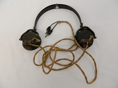
Headphone - Transmitter radio
... controls in an unusual system of radio telephone providing communication. At the time it was unique in Australia and installed by the S.E.C.V. technicians. It provided an unattended shortwave radio link between two ordinary telephone switchboards, connecting any of the S.E.C.V.'s internal lines with the telephone system at Bogong and the construction camps beyond. From Bogong, radio phones connect to the outpost stations on the High Plains far above the snow-line. In operation...controls in an unusual system of radio telephone providing communication. At the time it was unique in Australia and installed by the S.E.C.V. technicians. It provided an unattended shortwave radio link between two ordinary telephone switchboards, connecting any of the S.E.C.V.'s internal lines with the telephone system at Bogong and the construction camps beyond. From Bogong, radio phones connect to the outpost stations on the High Plains far above the snow-line. In operation ...Radio Telephone: Minuted during the war. It was approved in 1944 for State Electricity Commission of Victoria use only. It was completed by the end of 1946. Used by the State Electricity Commission of Victoria at Bogong during the construction of the Kiewa Hydro Electric Scheme to connect with head office in Melbourne. It allows one conversation at a time using traffic controls in an unusual system of radio telephone providing communication. At the time it was unique in Australia and installed by the S.E.C.V. technicians. It provided an unattended shortwave radio link between two ordinary telephone switchboards, connecting any of the S.E.C.V.'s internal lines with the telephone system at Bogong and the construction camps beyond. From Bogong, radio phones connect to the outpost stations on the High Plains far above the snow-line. In operation, the service is similar to a normal telephone system but dispenses with the physical connection of wires and poles between the main terminals.Historical: This type of headphone was used by operators on the switchboards at Bogong, Mt Beauty or on one of the construction camps on the Kiewa Hydro Electric Scheme. The S.E.C.V. installed this unique system of communication to operate their branches especially at Bogong and beyond where the distance was great and often limited by the weather and terrain.Used for a transmitter radio or Radio Telephone as installed by the State Electricity Commission of Victoria 2 round ear pieces. Outside of each ear piece has the brand inscribed, 4 screws and 1 small piece of metal. The metal has 2 screws attaching the the cord that goes to the 'switchboard'. On opposite edges of the earpieces is a thick metal piece that curves up to which the curved metal headpiece is attached and therefore connecting the earpieces. Each earpiece has a cord hanging from the small metal piece of earphone. This cord joins and then continues as one to the end where there are 2 metal pins coming out of the soft cover.'C-LR ST & C of Sydney'radio telephone. ear phones. headphones. communications. state electricity commission of victoria. kiewa hydro electric scheme. bogong. switchboards. -
 Kiewa Valley Historical Society
Headphone Set x2
... controls in an unusual system of radio telephone providing communication. At the time it was unique in Australia and installed by the S.E.C.V. technicians. It provided unattended shortwave radio link between two ordinary telephone switchboards, connecting any of the S.E.C.V.'s internal lines with the telephone system at Bogong and the construction camps beyond. From Bogong, radio phones connected to the outpost stations on the High Plains far above the snow-line. In operation...controls in an unusual system of radio telephone providing communication. At the time it was unique in Australia and installed by the S.E.C.V. technicians. It provided unattended shortwave radio link between two ordinary telephone switchboards, connecting any of the S.E.C.V.'s internal lines with the telephone system at Bogong and the construction camps beyond. From Bogong, radio phones connected to the outpost stations on the High Plains far above the snow-line. In operation ...Radio Telephone was minuted during the war. it was approved in 1944 for the State Electricity Commission of Victoria's use only. it was completed by the end of 1946. used by the State Electricity Commission of Victoria at Bogong during the construction of the Kiewa Hydro Electric Scheme to connect with head office in Melbourne. It allows one conversation at a time using traffic controls in an unusual system of radio telephone providing communication. At the time it was unique in Australia and installed by the S.E.C.V. technicians. It provided unattended shortwave radio link between two ordinary telephone switchboards, connecting any of the S.E.C.V.'s internal lines with the telephone system at Bogong and the construction camps beyond. From Bogong, radio phones connected to the outpost stations on the High Plains far above the snow-line. In operation, the service was similar to a normal telephone system but dispensed with the physical connection of wires and poles between the main terminals.Historical: This headphone set superseded headphones with two earpieces and those without a microphone. This one may have been used by operators on the switchboard at Bogong or Mt Beauty or one of the construction camps on the Kiewa Hydro Electric Scheme. The S.E.C.V. installed this unique system of communication to operate their branches especially at Bogong and beyond where the distance was great and often limited by the terrain and weather.Radio Telephone for SECV switchboard. Black plastic earpiece with microphone. Ear side circular with inscription on outer side then formed into elongated shape narrowing to the curved speaker piece at the narrow end. On top of the narrow end a long rubber cord is attached to a thick brass pin. On top of the wider end a thin stiff wire is attached to curve around the head to a blank rubber earpiece. This head piece has a piece of rectangular rubber attached at the top for comfort.'4408A IW61 / 1'radio telephone, ear phones, head phones. head set. communications, state electricity commission of victoria. kiewa hydro electric scheme. bogong. switchboards -
 Bendigo Military Museum
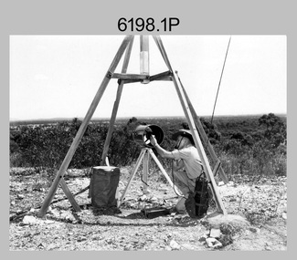
Photograph - Royal Australian Survey Corps Electronic Distance Measuring Equipment Demonstration, c1960s
... control operations. The photos were most likely taken in the late 1950s or early 1960s. The tellurometers of this era were man-portable systems that improved geodetic survey efficiencies for rapid network extension and densification replacing triangulation with EDM and theodolite traverse sometimes using Bilby Towers to extend line lengths. ...control operations. The photos were most likely taken in the late 1950s or early 1960s. The tellurometers of this era were man-portable systems that improved geodetic survey efficiencies for rapid network extension and densification replacing triangulation with EDM and theodolite traverse sometimes using Bilby Towers to extend line lengths. ...This is a set of five photographs of CAPT James ‘Jim’ Leslie Stedman in the field demonstrating the setup of prisms used as electric distance measurement (EDM) receiver reflectors for tellurometer equipment and the sighting of a large surveyor’s light. This equipment was deployed in establishing mapping and geodetic control operations. The photos were most likely taken in the late 1950s or early 1960s. The tellurometers of this era were man-portable systems that improved geodetic survey efficiencies for rapid network extension and densification replacing triangulation with EDM and theodolite traverse sometimes using Bilby Towers to extend line lengths. Jim Stedman later reached the rank of Colonel, was Director of Military Survey from 1975 to 1978 and was appointed as Colonel Commandant (honorary appointment, Retd) of the Royal Australian Survey Corps from 1978 to 1983. Jim Stedman is demonstrating EDM equipment. See item 6180.16P, photos .14) to .16) for more information and photos of Jim Stedman’s EDM demonstration. This is a set of five photographs of a surveyor in the field demonstrating electric distance measurement (EDM) equipment. c1950s – 1960s. The photographs were printed on photographic paper and are part of the Army Survey Regiment’s Collection. The photographs were scanned at 300 dpi. .1) to .2) - Photo, black & white, c1960s, CAPT Jim Stedman demonstrating the sighting of a large surveyor’s light. .3) to .5) – Photo, black & white, c1960s, CAPT Jim Stedman demonstrating EDM prism equipment. .1P to .5P on back – CAPT Stedman EDM Eqpt.royal australian survey corps, rasvy, army survey regiment, army svy regt, fortuna, asr, surveying -
 Bendigo Military Museum
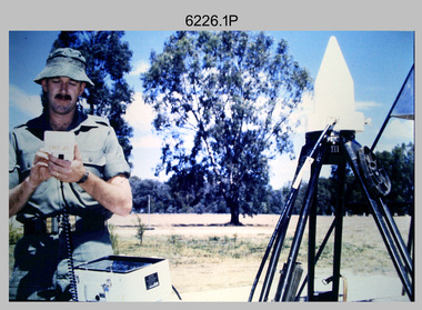
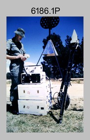
Photograph - Demonstration of TI4100 GPS Receiver, Royal Australian Survey Corps, c1988
... operation of Global Positioning System equipment in c1988. The photos were probably taken at the School of Military Survey (SMS), Bonegilla, VIC. Texas Instruments TI4100 portable Global Positioning System (GPS) geodetic receivers were introduced from 1986–1988. The GPS receivers and Ferranti FILS3 helicopter and vehicle mounted Inertial Positioning System (IPS) replaced the TRANSIT satellite receivers. The equipment was deployed to establish the baseline for a GPS controlled...operation of Global Positioning System equipment in c1988. The photos were probably taken at the School of Military Survey (SMS), Bonegilla, VIC. Texas Instruments TI4100 portable Global Positioning System (GPS) geodetic receivers were introduced from 1986–1988. The GPS receivers and Ferranti FILS3 helicopter and vehicle mounted Inertial Positioning System (IPS) replaced the TRANSIT satellite receivers. The equipment was deployed to establish the baseline for a GPS controlled ...This is a set of four photographs of WO2 Graham Ragless from the Royal Australian Survey Corps demonstrating the operation of Global Positioning System equipment in c1988. The photos were probably taken at the School of Military Survey (SMS), Bonegilla, VIC. Texas Instruments TI4100 portable Global Positioning System (GPS) geodetic receivers were introduced from 1986–1988. The GPS receivers and Ferranti FILS3 helicopter and vehicle mounted Inertial Positioning System (IPS) replaced the TRANSIT satellite receivers. The equipment was deployed to establish the baseline for a GPS controlled air camera and photogrammetric system to significantly reduce the requirement for ground survey to accurately control air photography for topographic mapping. Personnel from the four field survey squadrons at this time were trained at the SMS to operate the TI4100 receivers. Field survey operations using GPS and IPS equipment followed in the late 1980s. This technology is described in more detail in the RA Svy booklet titled An Introduction to Topographic Mapping. See record ID - 6010. WO2 Graham Ragless progressed to the rank of WO1 and was appointed as RSM of the Army Survey Regiment from 1990 to 1992. Refer to item 6186.2P for more photographs of WO2 Graham Ragless demonstrating the TI4100.This is a set of four photographs of a technician from the Royal Australian Survey Corps demonstrating the operation of Global Positioning System equipment in c1988. Colour photos are on 35mm slide film and were scanned at 96 dpi. .1) to .4) - Photo, colour, c1988, WO2 Graham Ragless demonstrating the operation of a TI4100 GPS receiverThere are no annotations.royal australian survey corps, rasvy, army survey regiment, army svy regt, fortuna, asr, surveying -
 Bendigo Military Museum
Photograph - Demonstration of TI4100 GPS Receiver, Royal Australian Survey Corps, c1988
... operation of Global Positioning System equipment in c1988. The photos were probably taken at the School of Military Survey (SMS), Bonegilla, VIC. Texas Instruments TI4100 portable Global Positioning System (GPS) geodetic receivers were introduced from 1986–1988. The GPS receivers and Ferranti FILS3 helicopter and vehicle mounted Inertial Positioning System (IPS) replaced the TRANSIT satellite receivers. The equipment was deployed to establish the baseline for a GPS controlled...operation of Global Positioning System equipment in c1988. The photos were probably taken at the School of Military Survey (SMS), Bonegilla, VIC. Texas Instruments TI4100 portable Global Positioning System (GPS) geodetic receivers were introduced from 1986–1988. The GPS receivers and Ferranti FILS3 helicopter and vehicle mounted Inertial Positioning System (IPS) replaced the TRANSIT satellite receivers. The equipment was deployed to establish the baseline for a GPS controlled ...This is a set of two photographs of WO2 Graham Ragless from the Royal Australian Survey Corps demonstrating the operation of Global Positioning System equipment in c1988. The photos were probably taken at the School of Military Survey (SMS), Bonegilla, VIC. Texas Instruments TI4100 portable Global Positioning System (GPS) geodetic receivers were introduced from 1986–1988. The GPS receivers and Ferranti FILS3 helicopter and vehicle mounted Inertial Positioning System (IPS) replaced the TRANSIT satellite receivers. The equipment was deployed to establish the baseline for a GPS controlled air camera and photogrammetric system to significantly reduce the requirement for ground survey to accurately control air photography for topographic mapping. Personnel from the four field survey squadrons at this time were trained at the SMS to operate the TI4100 receivers. Field survey operations using GPS and IPS equipment followed in the late 1980s. This technology is described in more detail in the RA Svy booklet titled An Introduction to Topographic Mapping. See record ID - 6010. WO2 Graham Ragless progressed to the rank of WO1 and was appointed as RSM of the Army Survey Regiment from 1990 to 1992. Refer to item 6226.4P for more photographs of WO2 Graham Ragless demonstrating the TI4100.This is a set of two photographs of a technician from the Royal Australian Survey Corps demonstrating the operation of Global Positioning System equipment in c1988. Colour photos are on 35mm slide film and were scanned at 96 dpi. .1) and .2) - Photo, colour, c1988, WO2 Graham Ragless demonstrating the operation of a TI4100 GPS receiverThere are no annotations.royal australian survey corps, rasvy, army survey regiment, army svy regt, fortuna, asr, surveying -
 Bendigo Military Museum
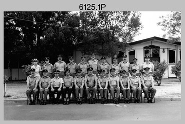
Photograph - Army Survey Regiment’s Officers, Warrant Officers and Sergeants and Squadrons, at Fortuna, Bendigo, 1982
... system and computer programming by civilians. Cartographic Squadron was responsible for the production of the following military products: Joint Operation Graphics, small-scale RAAF Air Charts, large-scale topographic line maps and orthophotomaps. Cartographic technician tasks were scribing, compiling, retouching, masking, type setting, type stickup, terrain embossing, correcting and proving quality control...system and computer programming by civilians. Cartographic Squadron was responsible for the production of the following military products: Joint Operation Graphics, small-scale RAAF Air Charts, large-scale topographic line maps and orthophotomaps. Cartographic technician tasks were scribing, compiling, retouching, masking, type setting, type stickup, terrain embossing, correcting and proving quality control ...This is a set of six staff photographs of the Army Survey Regiment’s Officers, Warrant Officers and Sergeants, and each of its four Squadrons at Fortuna, Bendigo in December 1982. Note - Air Survey Squadron’s photo was probably taken in July 1982 as they appear in winter dress. Air Survey Squadron was responsible for aerotriangulation, photogrammetric feature extraction and the AUTOMAP 1 system. Typical tasks were flight planning the acquisition of aerial photography, pugging, mensuration and block adjustments, photogrammetric extraction of topographic features from aerial photography, digital feature editing, map compilation, operating the scanner/plotter, operating the AUTOMAP 1 system and computer programming by civilians. Cartographic Squadron was responsible for the production of the following military products: Joint Operation Graphics, small-scale RAAF Air Charts, large-scale topographic line maps and orthophotomaps. Cartographic technician tasks were scribing, compiling, retouching, masking, type setting, type stickup, terrain embossing, correcting and proving quality control. Headquarters Squadron was responsible for the planning and coordination of map production and contracts. It also performed administrative and support functions such as personnel administration, pay, finance, transportation, records, map Library, kitchens, messes and facility maintenance. It was staffed by Army personnel from RASvy, RACT, AACC, RAAOC and RAEME corps. Other supporting staff at this time included the RAAF Liaison Officer, RAN Liaison Officer and several civilians employed in administration, the Q-Store and grounds maintenance. A component of the Army Svy Regt’s cartographic map production was carried out by the Detachment, a sub-unit located at Bonegilla next to the School of Military Survey. Lithographic Squadron was responsible for the reproduction of map materials and printing of military map products. The main tasks undertaken by photographic technicians were photographic enlargements, reductions and duplication of map reproduction material and processing of aerial photography. Printing technician tasks included platemaking, offset printing, map stock despatching and proofing.This is a set of six staff photographs of the Army Survey Regiment’s Officers, Warrant Officers and Sergeants, and its four Squadrons, at Fortuna, Bendigo, 1982. The black and white photographs were printed on photographic paper and are part of the Army Survey Regiment’s Collection. The photograph was scanned at 300 dpi. No personnel are identified. No personnel are identified. .1P – Annotated on front “OFFICERS MESS DEC ’82” .2P – Annotated on back “SGTS MESS DEC ’82” .4P– Annotated on front “CARTO SQN DEC ’82” .5P– Annotated on front “HQ SQN DEC ’82”royal australian survey corps, rasvy, army survey regiment, army svy regt, fortuna, asr, air survey, carto, litho -
 Kiewa Valley Historical Society
Timer Favag, Circa 1950
... This Favag Timer apparatus was a part of the first electronic control system -(1960's), in Victoria), which worked using telephone stepping selectors to convey a change in voltage providing a regulated pulse from the control centre(Mount Beauty) to the remote Power Stations opening and closing (stop/start) of various devices at the Power Station and a return signal confirmed the action taken. Testing of this unit was carried out using a "dummy" device at the remote Power Station so as not to disrupt the power plant's operation...Kiewa Valley Historical Society Mount Beauty Information Centre 31 Bogong High Plains Rd Mt Beauty high-country This Favag Timer apparatus was a part of the first electronic control system -(1960's), in Victoria), which worked using telephone stepping selectors to convey a change in voltage providing a regulated pulse from the control centre(Mount Beauty) to the remote Power Stations opening and closing (stop/start) of various devices at the Power Station and a return signal confirmed the action taken. Testing of this unit was carried out using a "dummy" device at the remote Power Station so as not to disrupt the power plant's operation ...This Favag Timer apparatus was a part of the first electronic control system -(1960's), in Victoria), which worked using telephone stepping selectors to convey a change in voltage providing a regulated pulse from the control centre(Mount Beauty) to the remote Power Stations opening and closing (stop/start) of various devices at the Power Station and a return signal confirmed the action taken. Testing of this unit was carried out using a "dummy" device at the remote Power Station so as not to disrupt the power plant's operation. This timer was one of many electrical apparatus connected to the large SEC Victoria Hydro Scheme's electrical power producing generators. These generators are powered by the hydro force of "stored" water at a higher altitude. The establishment of both the NSW and Victorian Hydro Schemes was achieved from the early 1900's to the 1960's. At this point in time the need for additional power sources to quench both an industrial and domestic demand for electricity was purely an economic and not and environmental (carbon reduction) factor. This hydro scheme was instigated by "the Government of the day" as a bold move and was the major force of the World War II refugee and "technical" workforce,inclusion of skilled and unskilled, migration into the Australian environment. Although this mass "invasion" of workers with families was thought of in some circles as intrusive, the expansion of population post war years and its integration into the Australian rural sector, produced the multi- lingual multi-cultural diversity of later years.This Favag Timer was one of the crucial pieces of equipment that made it possible for the Mount Beauty Terminal Station to control the operations of these Power Stations; McKay, Clover, West Kiewa Power Stations and the Dederang Terminal Station.This aluminium and anodised "FAVAG" (pulse) timer is fastened to a base structure which comes with its own metal cover that is fastened by two metal hooks. From the top of these hooks runs a thick leather "carry" strap.The instrument, itself, a small "micro motor" at one end tape feeding spool on the other. Aluminium metal structures offer a preventative barrier against any electronic spikes from static electricity sources. There are two toggle switches to the bottom right hand side and twelve coloured "pin" connection points.There is a sliding access sleeve which exposes a circuit board.with various leads fastened on each side. In front of one of this slide are two "screw in" fuses, spare fuses are in a small envelope taped above. Circuit diagrams are etched white on black background on the top face of the main structure. At the base of the back section is a two pronged input terminal. There is a fine black rubber layer (cushioning) for the mian top cover.On the cover fastened with two rivets "FAVAG" underneath in small print "Fabrique d'appareils electriques S.A." underneathe "NEUCHATEL-SUISSE". on one end is a "STATE ELECTRICITY COMMISSION OF VICTORIA" metal label screwed on.The back label has manufacturers' type and model number.sec vic kiewa hydro scheme, alternate energy supplies, alpine population growth -
 Bendigo Military Museum
Photograph - 4th Field Survey Squadron deployed on Operation NERIGHT, Queensland & Northern Territory, 1989
... Operation NERIGHT 89 Part 2 was the acquisition of mapping control by GPS field parties utilising Texas Instruments TI4100 Global Positioning System receivers around Weipa on Cape York Peninsula from the 22nd of September to the 22nd of October 1989. ...Operation NERIGHT 89 Part 2 was the acquisition of mapping control by GPS field parties utilising Texas Instruments TI4100 Global Positioning System receivers around Weipa on Cape York Peninsula from the 22nd of September to the 22nd of October 1989. ...This is a set of 19 photographs taken in 1989 during 4th Field Survey Squadron’s deployment on Operation NERIGHT 89 in Queensland and the Northern Territory. It was a two-part operation in 1989 with work conducted in the areas of Camooweal and Weipa. Part 1 was the field completion of topographic maps conducted near Camooweal QLD, along the Barkley Highway on the border between NT and QLD, from the 12th of September to the 20th of October 1989. A Bell Kiowa LOH helicopter from 162 Recce Sqn supported topographic field completion. Operation NERIGHT 89 Part 2 was the acquisition of mapping control by GPS field parties utilising Texas Instruments TI4100 Global Positioning System receivers around Weipa on Cape York Peninsula from the 22nd of September to the 22nd of October 1989. Part 2 Two Bell UH-1H Iroquois helicopters from RAAF’s 35 Squadron were principally used to deploy GPS field parties. Identification photography of control points was taken by air camera operators in AAAvn Pilatus Porter aircraft from 173 Gen Spt Sqn fitted with an RC10 aerial camera. The two parts of the operation were conducted concurrently. This is a set of 19 photographs taken in 1989 during 4th Field Survey Squadron’s deployment on Operation Neright in Queensland & the Northern Territory. The colour photographs are on 35mm negative film and are part of the Army Survey Regiment’s Collection. The photographs were scanned at 96 dpi. .1) to .3) - Photo, colour, 1989. En-route to areas of survey operations. .4) to .5) - Photo, colour, 1989. Unidentified personnel relax next to river/waterhole. .6) - Photo, colour, 1989. Two Bell UH-1H Iroquois helicopters from RAAF’s 35 SQN utilised in the movement of GPS parties. .7) to .9) - Photo, colour, 1989. Unidentified soldier practices repelling from a UH1H Iroquois helicopter. .10) - Photo, colour, 1989. Inside the cockpit of a UH1H Iroquois helicopter. .11) - Photo, colour, 1989. Field Party camp with GPS equipment in foreground. Unidentified soldier prepares a meal. .12) - Photo, colour, 1989. GPS antenna plumbed over a survey ground mark. Witness post on left. .13) & .14) - Photo, colour, 1989. Unknown Cape York Peninsula beaches. .15) & .16) - Photo, colour, 1989. Dramatic fire next to base camp. .17) - Photo, colour, 1989. Aboriginal rock art at unknown location. .18) - Photo, colour, 1989. Aboriginal rock art at unknown location. L to R: unidentified, SPR Andrew Quin. .19) - Photo, colour, 1989. Aboriginal rock art at unknown location. LT Chris Topovsek..1P to .19P – There are no personnel identified. ‘1989 OP NERIGHT’ annotated on negative sleeve.royal australian survey corps, rasvy, 4 fd svy sqn, op neright 89 -
 Bendigo Military Museum
Photograph - 4th Field Survey Squadron – Operation ARIGHT 91, Queensland, 1991
... operations was the top end of the Cape York Peninsula, islands of the Torres Strait and the southern coast of PNG. Field parties utilised Texas Instruments TI4100 Global Positioning System receivers. Concurrent with GPS operations Doppler point positioning observations were carried out by field parties using Magnavox MX 1502 receivers on six of the control points. ...operations was the top end of the Cape York Peninsula, islands of the Torres Strait and the southern coast of PNG. Field parties utilised Texas Instruments TI4100 Global Positioning System receivers. Concurrent with GPS operations Doppler point positioning observations were carried out by field parties using Magnavox MX 1502 receivers on six of the control points. ...This is a set of 16 photographs taken during 4th Field Survey Squadron’s deployment on Operation ARIGHT 91 in Queensland from the 8th of July to the 5th of September 1991. The area of operations was the top end of the Cape York Peninsula, islands of the Torres Strait and the southern coast of PNG. Field parties utilised Texas Instruments TI4100 Global Positioning System receivers. Concurrent with GPS operations Doppler point positioning observations were carried out by field parties using Magnavox MX 1502 receivers on six of the control points. Two Bell UH-1H Iroquois helicopters from RAAF’s 171 COMD and Liaison Squadron were primarily used to deploy GPS field parties. Identification photography of control points was taken by air camera operators in AAAvn Pilatus Porter aircraft from 173 Gen Spt Sqn fitted with an RC10 aerial camera.This is a set of 16 photographs taken in 1991 during 4th Field Survey Squadron’s deployment on Operation ARIGHT in Queensland. The colour photographs are on 35mm negative film and are part of the Army Survey Regiment’s Collection. The photographs were scanned at 96 dpi. .1) to .3) - Photo, colour, 1991. Area of Operations (AO) coordination maps. .4) - Photo, colour, 1991. GPS acquisition post-processing. L to R: LT Simon Buckpitt, SSGT Steve Winner, WO2 Ken Talbot-Smith. .5) to .6) - Photo, colour, 1991. Base camp unidentified personnel. .7) - Photo, colour, 1991. L to R: OPS WO - WO2 Ken Talbot-Smith, DET SSM WO1 Stevo Hinic. .8) - Photo, colour, 1991. Base camp unidentified personnel. .9) - Photo, colour, 1991. Base camp L to R: unidentified (x2), OPS WO - WO2 Ken Talbot-Smith. .10) - Photo, colour, 1991. Base camp unidentified soldier. .11) - Photo, colour, 1991. Base camp L to R: CPL Andy Love, unidentified, SGT Steve McGuiness. .12) - Photo, colour, 1991. Base camp at Horn Island Army Compound. .13 to .16) - Photo, colour, 1991. Unknown locations in Area of Operations..1P to .16P – There are no personnel identified. ‘1991 OP ARIGHT’ annotated on negative sleeve.royal australian survey corps, rasvy, 4 fd svy sqn, op aright 91 -
 Bendigo Military Museum
Photograph - 4th Field Survey Squadron – Operation MIZMAZE 92, Kimberley region, Western Australia, 1992
... It was a two-part operation involving the field completion of topographic maps and the acquisition of mapping control by GPS field parties utilising Texas Instruments TI4100 Global Positioning System receivers. ...It was a two-part operation involving the field completion of topographic maps and the acquisition of mapping control by GPS field parties utilising Texas Instruments TI4100 Global Positioning System receivers. ...This is a set of 40 photographs taken in 1992 during 4th Field Survey Squadron’s deployment on Operation MIZMAZE 92 in the Kimberley region of Western Australia from the 13th of May to the 14th of July 1992. The area of operations was Wyndham, Halls Creek and Sandfire Flat. It was a two-part operation involving the field completion of topographic maps and the acquisition of mapping control by GPS field parties utilising Texas Instruments TI4100 Global Positioning System receivers. Survey parties conducted field checking of topographic maps and GPS control acquisition in Perentie 110 Series Survey variant FFR Land Rovers. Three Bell Kiowa LOH helicopters provided by 162 Recce Sqn supported field checking and limited deployment of GPS surveys parties. C-l30 Hercules from 36 Sqn supported deployment and extraction of personnel and equipment to and from from the AO. A Cessna 404 Titan Ambassador from Vee-H Aviation was used as the Wild RC10 camera platform for aerial photography acquisition.This is a set of 40 photographs taken in 1992 during 4th Field Survey Squadron’s deployment on Operation MIZMAZE 92 in the Kimberley region of Western Australia. The colour photographs are on 35mm negative film and are part of the Army Survey Regiment’s Collection. The photographs were scanned at 96 dpi. .1) - Photo, colour, 1992. CAPT Craig Hersant. .2) - Photo, colour, 1992. Unidentified officer/soldier. .3) & .4) - Photo, colour, 1992. Aboriginal rock art - Wandjina Gunduran, Donkey Creek. .5) - Photo, colour, 1992. Aboriginal rock art - Track Wandjinas, Donkey Creek. .6) & .7) - Photo, colour, 1992. CAPT Craig Hersant. .8) - Photo, colour, 1992. Kimberley region topography. CPL Glen Weatherell. .9) - Photo, colour, 1992. Unidentified personnel .10) - Photo, colour, 1992. Supermarket at unknown location. .11) to .13) - Photo, colour, 1992. Caravan park at unknown location. .14) - Photo, colour, 1992. Old bridge at Fitzroy Crosssing. .15) & .16) - Photo, colour, 1992. Survey party in Perentie 110 Series Land Rover. .17) & .18) - Photo, colour, 1992. Kimberley region topography. .19) - Photo, colour, 1992. Kimberley region topography. CPL Glen Weatherell. .20) - Photo, colour, 1992. Kimberley region topography, possibly the Bungle Bungles. .21) - Photo, colour, 1992. Kimberley region topography. SGT Frank Downie. .22) - Photo, colour, 1992. Kimberley region topography: the Bungle Bungles. .23) - Photo, colour, 1992. Kimberley region topography: the Bungle Bungles. .24) - Photo, colour, 1992. Kimberley region topography: the Bungle Bungles. SPR Neil Pedler. .25) & .26) - Photo, colour, 1992. Kimberley region topography: the Bungle Bungles. .27) - Photo, colour, 1992. Kimberley region topography. .28) - Photo, colour, 1992. Survey party with Perentie 110 Series Land Rover. .29) - Photo, colour, 1992. Kimberley region topography. .30) - Photo, colour, 1992. Survey party outside Perentie 110 Series Land Rover. .31) & .32) - Photo, colour, 1992. Survey party operating TI4100 GPS Receiver next to Perentie 110 Series Land Rover. SGT Eddie Jacobs. .33) & .34) - Photo, colour, 1992. Survey party operating TI4100 GPS Receiver next to Perentie 110 Series Land Rover. Unidentified surveyor. .35) - Photo, colour, 1992. Kimberley region topography. Hand water pump at well. .36) - Photo, colour, 1992. Survey party in Perentie 110 Series Land Rover. .37) - Photo, colour, 1992. Kimberley region topography. CPL Glen Weatherell. .38) - Photo, colour, 1992. Kimberley region topography viewed from Bell Kiowa LOH helicopter. .39) & .40) - Photo, colour, 1992. Unidentified surveyor field checking a preliminary map in a Bell Kiowa LOH helicopter..1P to .40P – There are no personnel identified. ‘1992 OP MIZMAZE annotated on negative sleeve.royal australian survey corps, rasvy, 4 fd svy sqn, op mizmaze 92 -
 Orbost & District Historical Society
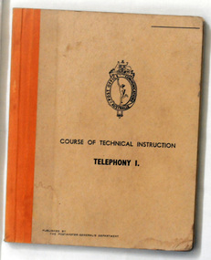
book, Australian Postmaster General's Dept, Course of Technical Instruction and Telegraphy, 1940's -1950's
... control over all six Colonies (States) Postal and Telegraphic services within Australia to form the national Postal and Telegraphic services within Australia. The Department was administered by the Postmaster-General. This manual was produced as a syllabus of training for Army Personnel units in P.M.G's Department schools. In war times the postal organisation was a vital link between the services, the community and overseas centres. The Postmaster-General's Department co-operated with service departments in the installation and operation of radio, telephone and telegraph systems ...The Postmaster-General's Department (P.M.G.) of Australia was created in 1901 with Federation taking control over all six Colonies (States) Postal and Telegraphic services within Australia to form the national Postal and Telegraphic services within Australia. The Department was administered by the Postmaster-General. This manual was produced as a syllabus of training for Army Personnel units in P.M.G's Department schools.In war times the postal organisation was a vital link between the services, the community and overseas centres. The Postmaster-General's Department co-operated with service departments in the installation and operation of radio, telephone and telegraph systems. Its laboratories also designed, developed and manufactured vital defence equipment. This item reflects that contribution and history.A 31 pp buff colored book with orange cloth binding. Black print on the front cover - a oval shaped logo with Post Office Communication Australia around a small sketch depicting Mercury, the messenger of the gods below an Australian coat-of-arms. Below that is the title,"COURSE OF TECHNICAL INSTRUCTION TELEPHONY 1".manual-telephony postmaster-general's-training-department instruction-book communications -
 Eltham District Historical Society Inc
Document - Folder, Aerospace Industry, 1958-1961
... The missile submarine system; The New Scientist, 10 November 1960, pp 1238-1239 8. Satellite Situation Report, February 14, 1961; Space operations Control Center, Goddard Space Flight Center, National Aeronautics and Space Administration, Greenbelt, Maryland; 4 pages 9. ...The missile submarine system; The New Scientist, 10 November 1960, pp 1238-1239 8. Satellite Situation Report, February 14, 1961; Space operations Control Center, Goddard Space Flight Center, National Aeronautics and Space Administration, Greenbelt, Maryland; 4 pages 9. ...honeywell, scout rocket, echo satellite, mercury rocket, centaur rocket, advent rocket, mariner satellite, dyna soar, x-15, midas rocket, tiros satellite, discoverer rocket, vanguard satellite, aerospace industry, alan gardiner collection, space industry -
 Flagstaff Hill Maritime Museum and Village
Timer, 1940s
... system became increasingly unsuitable. More trunk operators had to be employed and so labour costs increased. It was a tedious and slow way of making a long-distance call, and it was sometimes hard to hear, particularly when several exchanges were linked With technical advances, trunk switching moved from manual operation through a partly automatic phase. Automatic transit switching equipment was used and only a single operator was required to connect a trunk call to a wanted automatic subscriber. Until well beyond the middle of this century, the majority of trunk traffic went through this single telephonist control...system became increasingly unsuitable. More trunk operators had to be employed and so labour costs increased. It was a tedious and slow way of making a long-distance call, and it was sometimes hard to hear, particularly when several exchanges were linked With technical advances, trunk switching moved from manual operation through a partly automatic phase. Automatic transit switching equipment was used and only a single operator was required to connect a trunk call to a wanted automatic subscriber. Until well beyond the middle of this century, the majority of trunk traffic went through this single telephonist control ...Australia's first telephone exchange was opened in Melbourne in August 1880. It was operated by the Melbourne Telephone Exchange Company. Owned by W. H. Masters and T. T. Draper, the Manager of the Company was H. Byron Moore. This was only two years after the world's first exchange in the United States, and just four years after Bell first spoke on a telephone. The exchange was located in the old Stock Exchange building at 367 Collins Street, a site now occupied by the Commonwealth Bank. In 1884, the operations of the Company, by then known as the Victorian Telephone Exchange Company, had grown considerably and were transferred to Wills Street, Melbourne. Private ownership of this company continued until 1887 when it was bought out by the Victorian Colonial Government. Other colonial governments followed this example. By 1910, the growth in telephone services made additional accommodation necessary. This could not be provided in the existing building in Wills Street and arrangements were made for a new exchange in Lonsdale Street. Alexander Graham Bell visited Australia in 1910 to advise the Federal Government's Postal Commission. Telephone exchanges were established in Adelaide with (48 subscribers), Hobart (10 subscribers) and Launceston (35 subscribers). The first exchange in Western Australia was established in 1887 and located in a small three-room cottage in Wellington Street, Perth with 17 subscribers. The year 1888 marked the opening of the Fremantle exchange in a small room at the rear of the Town Hall. There were nine subscribers. Australia's first automatic exchange was installed in the GPO in Sydney, in 1911, for internal use. But the first automatic exchange for public use was opened at Geelong in Victoria in the next year July 1912 with 800 subscribers. Melbourne's first automatic exchange was opened in the suburb of Brighton in 1914; the first public automatic exchange in NSW began operating at Newtown, Sydney in 1915; and Queensland's first was installed at South Brisbane in 1925. 1929 saw the opening of Tasmania's first automatic exchange in Hobart. an automatic telephone service. In June 1977, the manual telephone exchange at Swansea was replaced with an automatic service and made Tasmania the first State in Australia to have a fully automatic net work. The half-century following Federation saw the growth of the automatic operation; a great extension of trunk line services; The automatic telephone contributed greatly to the early popularity of telephones in Australia. It was a quicker and more convenient way of communicating with another person on the same exchange — instead of having to go through tedious processes with the operator. From its introduction, the number of automatic telephones in operation grew to a remarkable extent. In 1886, the first trunk link of 16 km was connected to the exchanges of Adelaide and Port Adelaide in South Australia. Then, in 1907, the first inter-capital telephone trunk line was opened between Sydney and Melbourne. It was followed by a line between Melbourne and Adelaide in 1914. Sydney and Brisbane were linked in 1923, and Perth and Adelaide in 1930. In 1930, the first overseas calls from Australia came possible with the introduction of a radio telephone service to England, and through there to Europe and America. A similar service opened to New Zealand in the same year. Initially, trunk channels linked different manual trunk exchanges. It was necessary for a succession of trunk operators to connect the appropriate channels, one after the other until the connection was made. As trunk traffic grew. the system became increasingly unsuitable. More trunk operators had to be employed and so labour costs increased. It was a tedious and slow way of making a long-distance call, and it was sometimes hard to hear, particularly when several exchanges were linked With technical advances, trunk switching moved from manual operation through a partly automatic phase. Automatic transit switching equipment was used and only a single operator was required to connect a trunk call to a wanted automatic subscriber. Until well beyond the middle of this century, the majority of trunk traffic went through this single telephonist control. In 1953, the number of telephones in use in Australia passed the one million mark. By then, the need for improvement in the automatic exchanges was be coming well recognised. The need was for a telephone switching system which would do a better job more economically than the conventional step-by-step ex-change. This led to the adoption of the Crossbar system as the standard in automatic telephone exchanges in 1960. The introduction of Crossbar switching was a big step forward in the automation of trunk calls. It substituted automatic switching and charging equipment for the originating trunk operator, and improved the quality of the system radically. Before the introduction of the Crossbar system there were often very long delays in obtaining a booked trunk call, and the quality of sound was often very poor. With Crossbar, Subscriber Trunk Dialing (STD) became a reality. A trunk call by STD was as easy to make and almost as fast to connect as a local call.The item was made around the 1940s and used up until the 1970s in manual cord telephone exchanges as a way to time and charge users for trunk calls made over the telecom system of the time. Post Master General dept. - Trunk Call Timer.Inscribed PMG, C. of A, 37. Bell chimes at 3 min increments.flagstaff hill, warrnambool, shipwrecked-coast, flagstaff-hill, flagstaff-hill-maritime-museum, maritime-museum, shipwreck-coast, flagstaff-hill-maritime-village, timer, trunk call, telephone, cord exchange -
 City of Moorabbin Historical Society (Operating the Box Cottage Museum)
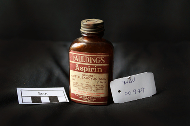
Manufactured Glass, brown bottle 'Fauldings Aspirin', c1950
... operations in Exhibition Street, Melbourne, eventually adding wholesale activities. 1986 With a presence in every city, from Darwin to Tasmania. Faulding becomes a truly national company. 2008 Zuelllig Group takes control Focusing solely on pharmaceutical wholesaling and distribution, Hong Kong based Zuelllig Group takes over control of Symbion Pharmacy Services. 2008 Symbion Pharmacy Services exceeds $3 billion with one of the country's largest networks of warehousing systems and service ...operations in Exhibition Street, Melbourne, eventually adding wholesale activities. 1986 With a presence in every city, from Darwin to Tasmania. Faulding becomes a truly national company. 2008 Zuelllig Group takes control Focusing solely on pharmaceutical wholesaling and distribution, Hong Kong based Zuelllig Group takes over control of Symbion Pharmacy Services. 2008 Symbion Pharmacy Services exceeds $3 billion with one of the country's largest networks of warehousing systems and service pharmacy medicines faulding f.h. scammell luther faulding's aspirin glassware bottles moorabbin bentleigh cheltenham antiseptics analgesics pharmaceuticals south australia ss nabob f.h.faulding & co. ...Francis Hardy Faulding 1816 – 1868 arrived in Sydney 1842. He was a Surgeon on the emigrant ship Nabob. 1845 Francis Hardy Faulding opened his first pharmacy at 5 Rundle Street in Adelaide and the business prospered. In 1867 he formed F.H Faulding & Co with Luther Scammel. as wholesale druggists and manufacturing chemists. Two of the Faulding company's major innovations were the development of a process for distillation of eucalyptus oil, and the development of the test for determining the eucalyptol content of the oil. Faulding's success was founded on eucalyptus oil, which formed the basis of an antiseptic marketed as "Solyptol" In 1868 Francis Hardy Faulding died, aged 52 at his suburban Glen Osmond home in Adelaide. Scammel’s two sons took over the business in 1888 and in 1890 the Company expanded to West Australia, then Sydney, Brisbane and finally, in 1924, Faulding began operations in Exhibition Street, Melbourne, eventually adding wholesale activities. 1986 With a presence in every city, from Darwin to Tasmania. Faulding becomes a truly national company. 2008 Zuelllig Group takes control Focusing solely on pharmaceutical wholesaling and distribution, Hong Kong based Zuelllig Group takes over control of Symbion Pharmacy Services. 2008 Symbion Pharmacy Services exceeds $3 billion with one of the country's largest networks of warehousing systems and service A brown glass, bottle with a metal screw top containing ‘Faulding's Aspirin’ tabletsFront label : FAULDINGS / ASPIRIN / GENUINE / ACETYL SALICYLIC ACID / 100 Gr 5 / for / Colds, .............. / DOSE ........... / F.H.FAULDING & CO LTD / MANUFACTURING CHEMISTS / AUSTRALIApharmacy, medicines, faulding f.h., scammell luther, faulding's aspirin, glassware, bottles, moorabbin, bentleigh, cheltenham, antiseptics, analgesics, pharmaceuticals, south australia, ss nabob, f.h.faulding & co. -
 Federation University Historical Collection
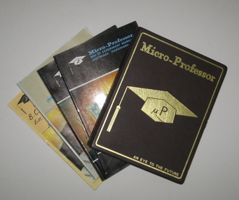
Computer, Mutlitech Industrial Corporation, Micro-Professor MPF-IP and manuals, 1983 (estimated)
... system featuring sophisticated software and hardware capabilities. (MPF-IP) boasted a display panel with the ability to display 20 characters using 16-segment fonts. All 64 standard ASCII characters could be displayed. The operation of the MPF-IP was controlled...system featuring sophisticated software and hardware capabilities. (MPF-IP) boasted a display panel with the ability to display 20 characters using 16-segment fonts. All 64 standard ASCII characters could be displayed. The operation of the MPF-IP was controlled ...The Micro-Professor I Plus (MPF-IP) was a low cost, versatile microcomputer system featuring sophisticated software and hardware capabilities. (MPF-IP) boasted a display panel with the ability to display 20 characters using 16-segment fonts. All 64 standard ASCII characters could be displayed. The operation of the MPF-IP was controlled by an 8k monitor program which resides in the Read Only Memory (ROM). The monitor, aided by 4k Random Access Memory (RAM), enabled the user to enter a comprehensive set of single keystroke commands, making it easier for the user to use the CPU, memory and I/0 devices. This allowed the user to concentrate of microprocessor software development and application design. The system allowed printing at 48 lines per minute, and the ability to permanently record the commands, data, programs, status and other messaged. Each character printed by the printer is in a 5 by 7 dot matrix. Although the prime purpose of the programming was for machine language object code formed as hexadecimal numbers, the Micro-Professor has an embedded Tiny Basic interpreter for which formation of some of the alpha characters using a standard 7 segment display was ingenious. The program memory consisted of non volatile 2 kilobytes electrically programmable ROM whilst the Random Access Memory came with 2 kilobytes of static RAM but could be upgraded to 4 kilobytes by insertion of another chip. The entire memory space of 64 kilobytes was accessible by way of the terminals on the left hand side of the board. Engineering and Science students from the Ballarat School of Mines and the Ballarat College of Advanced Education used a class set (as they were relatively inexpensive at approx. $100 each) during the mid to late 1980s. Student were encouraged to borrow the Micro-Professors in order to assist in learning how to use them. Only one was ever not returned on time. When pressed to return the device the student confessed that his dog had chewed the plastic case. This is still in our collection complete with bite marks! The Micro-Professor used a Zilog Z80 microprocessor. This was the most powerful of the 8 bit microprocessors at the time. Zilog was derived from the Intel 8080 microprocessor. The Z80 had 158 instructions of which the Intel 78 instructions were a subset. The Intel processor continued on through development in the IBM computers as 8086, 80286, 80386, 80486 and later the pentiums. Zilog lost most of its market share when it developed the 16 bit Z8000 microprocessor. Although the microprocessor was excellent, the lack of peripherals caused users to abandon Zilog products. A brown and gold plastic box containing a microcomputer for use in classrooms. Four manuals are titled 'Micro-Professor MPF-IP user's Manual', 'MPF-I Experiment Manual (Software/Hardware)', Micro-professor MPF-IP experiment Manual (Software/Hardware)' and Micro-Professor MPF-I Monitor Program Source Listing.microcomputer, micro computer, micro professor, electronics -
 Federation University Historical Collection
Object, Synchronome Co. Ltd, Synchronome Frequency Checking Master Clock No. 2191, c1930
... operation for precise time regulation. There are two normal time dials and one is controlled by the pendulum and the other is operated by the system frequency. ...operation for precise time regulation. There are two normal time dials and one is controlled by the pendulum and the other is operated by the system frequency. ...Information from Norman F. Dalton: Ballarat had a reticulated DC supply in the early part of last century and in 1905 had sufficient generating capacity to enable the trams to be changed from horse drawn to DC electricity. The use of electricity increased with the main power station located on Wendouree Parade, near Webster Street, under the ownership of The Electric Supply Company of Victoria. AC generating plant was installed in 1925 and conversion to AC proceeded. In 1934 the company was taken over by the State Electricity Commission Victoria (SECV) and more AC generation was installed and the changeover of customers was accelerated. This is around the time that the Synchronome Frequency Checking Mast Clock was installed at the Wendouree Parade Power Station. The SECV Annual Report of 1921 states: ::Section 11 of the act directed the COmmission to enquire into the question of securing the adoption of such standards of plant and equipment of a system, frequency and pressure for the generation and distribution of electricity as will admit of the efficient interconnection of undertakings throughout the State. In 1934 when the SECV took over the Ballarat operations the question of linking with the State grid had been a planned operation for some years but due to financial considerations had hindered it and in fact would continue to do so for a further 10 years. So while the need for close frequency control for interconnection was hardly an issue, the need to keep electric clocks correct was important, particularly as this item was a frequent sales point to cover the inconvenience and sometimes expense of converting from DC to AC. The clock is a very accurate pendulum clock with provision for varying effective length during operation for precise time regulation. There are two normal time dials and one is controlled by the pendulum and the other is operated by the system frequency. When the clock was in use it was installed by the MEter and Tests Laboratory and the time was checked daily by radio time signals. The two dials were repeated in the operators control panel in the Power Station. A maximum deviation between the two dials was set in the operating instructions (eg 5 seconds) and the operator would correct this when necessary by remote manual alteration of the turbine governor set point. The clock was used to drive and regulate a system of "slave" clocks which were used to display the time in various locations around the power station. A slave clock is a simple clock which is driven by a small electric motor, its accuracy is regulated by the master clock every 30 seconds to ensure that it and all the other slave clocks in the station are on exactly the right time; slave clocks were placed in various locations, from common rooms to workshops. A master clock could potentially run thousands of slave clocks at one plant. The clock also contains a rectifier. A rectifier is a device that is used to convert AC power to more stable DC current.Two clocks in a timber case. Both are electric, one is powered by the main pendulum mechanism, the other is a self contained electric clock. The main mechanism is of the gravity arm and roller type, which sends an impulse to the slave clocks every 30 seconds. The This Synchronome Frequency Checking Master Clock was used at the Ballarat Power Station. Below the main section of the case is a smaller cabinet containing a rectifier to provide consistent DC power for the clock. The rectifier was made by the Victorian company Hilco, which was located in Burwood. There is a high chance this is not the original rectifier from this clock as there appears to be brackets to hold a larger device in the space the rectifier occupies.Front below main clock face on front of case: "Patented Sychronome Brisbane" Lower left-hand clock face: "Frequency time" Lower right-hand clock face: "Standard Seconds" Synchronous electric clock mechanism on door (Frequency time clock): >200/250 V. 50~ >"Synchronomains" Made in England >Direction indicator for clock starting switch >"To start move lever in direction of arrow and release" >"Patent applied for" Mechanism for "standard seconds" clock: >"English Made" >"Patented" >Serial number "321" >0 above right-hand pillar on front-plate Mechanism for "standard seconds" clock: >"English Made" >"Patented" >Serial number "321" >0 above right-hand pillar on front-plate Mechanism for main clock face: >"English Made" >"Patented" >Serial number "8751" >0 above right-hand pillar on front-plate Inside case, back panel, top enamel plate: >Seconds Battery + Pos. > Battery Common or - Neg. >1/2 min dials Inside case, back panel, bottom enamel plate: external seconds dial Inside case, right hand side, electrical knobs: two switches, both "A.C. mains" Pendulum rod, below suspension spring: Serial number (?) 0000005 Rectifier in bottom cabinet: >"Hilco Rectifier" >"A.C. Volts 230/240" >"Model 1060/S" >"A.C. Amperes" >"Serial No. 1060/S >"Phases 1" >"D.C. Volts 6" >"C.P.S. 50" >"D.C. Amperes 1" >"Made in Australia by Hilco Transformers McIntyre St., Burwood, Victoria." Bakelite electrical plug: makers mark Lower cabinet, RH side panel, pressed tin plate: "AC" (upside down) Brass speed adjustment, outer right RH side: "S" and "F" Ivory and wood pendulum beat ruler: >Ruler, with 0 in centre and numbers 1-5 in ascending order from centre on left and right. > "Synchronome Patent." Steel plate, back panel, inside case, right hand side: >N R A" (descending) >"2191" serial number/part number Face of main clock: "Synchronome Electric" synchronome frequency checking master clock, electricity, state electricity commission, wendouree parade power station, secv, clock, time, pendulum, electric supply company of victoria, norman f. dalton, ballarat power station, rectifier, slave clock -
Ballarat Tramway Museum
Drawing - VB4/8757/7, State Electricity Commission of Victoria (SECV), "Signalling System. Modified type by non-car counting signals. Line diagram of operation", 1938
... control wiring diagrams and how the drawing was used in the workshops in Ballarat. SECV State Electricity Commission of Victoria Ballarat Ballarat Tramways Motors Controllers Wiring Diagrams Westinghouse Some damage to the bottom right hand corner near "Passed". SEC drawing number VB4/8757/7, "Signalling System. Modified type by non-car counting signals. Line diagram of operation ...Yields information about motor and control wiring diagrams and how the drawing was used in the workshops in Ballarat.SEC drawing number VB4/8757/7, "Signalling System. Modified type by non-car counting signals. Line diagram of operation". Drawn 26/02/1938 BTM. Black dyeline print on beige paper.Some damage to the bottom right hand corner near "Passed".secv, state electricity commission of victoria, ballarat, ballarat tramways, motors, controllers, wiring diagrams, westinghouse -
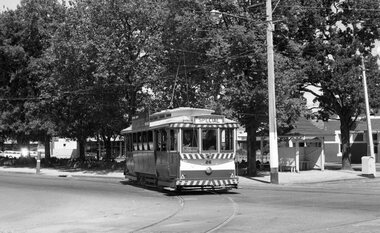 Ballarat Tramway Museum
Negative - SECV Ballarat operations set of 6, Robert Green, 2/3/1969
... Set of 6 photographs by Robert Green during 3/2/1969, showing the tramcar operations of the SECV system when the TMSV visited Ballarat. 1 -Tram 26 Turning from Ripon St into Sturt St 2 -Tram 26 reversing at Hospital corner for Drummond St South 3 -Trams 26, 12 crossing at the Grey St loop 4 -Tram 26 Bob Prentice at the controls 5 -Tram 26 at Sebastopol terminus with Keith Kings standing inside the tram 6 -Trams 13, 26 at the Sebastopol terminus. ...Ballarat Tramway Museum South Gardens Reserve Wendouree Parade Ballarat Ballarat goldfields Set of 6 photographs by Robert Green during 3/2/1969, showing the tramcar operations of the SECV system when the TMSV visited Ballarat. 1 -Tram 26 Turning from Ripon St into Sturt St 2 -Tram 26 reversing at Hospital corner for Drummond St South 3 -Trams 26, 12 crossing at the Grey St loop 4 -Tram 26 Bob Prentice at the controls 5 -Tram 26 at Sebastopol terminus with Keith Kings standing inside the tram 6 -Trams 13, 26 at the Sebastopol terminus. ...Set of 6 photographs by Robert Green during 3/2/1969, showing the tramcar operations of the SECV system when the TMSV visited Ballarat. 1 -Tram 26 Turning from Ripon St into Sturt St 2 -Tram 26 reversing at Hospital corner for Drummond St South 3 -Trams 26, 12 crossing at the Grey St loop 4 -Tram 26 Bob Prentice at the controls 5 -Tram 26 at Sebastopol terminus with Keith Kings standing inside the tram 6 -Trams 13, 26 at the Sebastopol terminus. Tram 13 has a Twin Lakes and a Trotting Bray Raceway Auxiliary board Yields information about the SECV Ballarat tramways operations on the day of the visit of the TMSV to Ballarat.35mm negative in a film strip - set of 6tramways, tmsv tours, tram 21, tram 26, ripon st, sturt st, hospital corner, drummond st sth, tram 12, grey st, sebastopol, tram 13 -
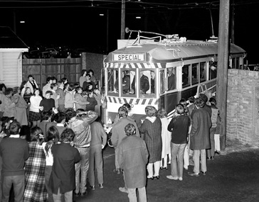 Ballarat Tramway Museum
Photograph - Digital Image, Greg Triplett, No 40 the very last tram at the depot gates, 19-9-1971
... controls. Taken on the last day of operation of the SEC Ballarat tramway system - 19-9-1971. ...controls. Taken on the last day of operation of the SEC Ballarat tramway system - 19-9-1971. ...No 40 the very last tram at the depot gates - Greg Triplett, with Lou Walker at the controls. Taken on the last day of operation of the SEC Ballarat tramway system - 19-9-1971. Yields information about the last day of operation of the Ballarat SEC tramways.Digital image - 120 negative tramways, tramcars, ballarat, last day, closure, tram 40, last tram -
 Ballarat Tramway Museum
Pamphlet, The Forest City Electric Co. Limited England, "Collins Patent Automatic Point Turner", c1940's?
... systems, not actually used in Ballarat or Bendigo. Trams tramways Forest City Signals Level Crossings Signals Has “217” in biro in bottom left hand corner. Four page Pamphlet or Brochure Forest City No. 19, "Collins Patent Automatic Point Turner". Four page printed brochure with illustrations 1940’s? describing the Point turning mechanism with illustrations, of the equipment, method of operation advantages, wiring, the street box and curb (kerb) control ...Yields information about the types of automatic point Turing mechanisms used on tramway systems, not actually used in Ballarat or Bendigo.Four page Pamphlet or Brochure Forest City No. 19, "Collins Patent Automatic Point Turner". Four page printed brochure with illustrations 1940’s? describing the Point turning mechanism with illustrations, of the equipment, method of operation advantages, wiring, the street box and curb (kerb) control box. c1940's? Has “217” in biro in bottom left hand corner.trams, tramways, forest city signals, level crossings, signals -
 Ballarat Tramway Museum
Document - Photocopy, The Courier Ballarat, "Tramway book is on track", 4/01/2008 12:00:00 AM
... controls of a bogie tram. Gives a quick detail of the three SEC systems and the Museum's operations. ...controls of a bogie tram. Gives a quick detail of the three SEC systems and the Museum's operations. ...Colour Photocopy of a newspaper clipping, A4 size, from The Courier, Ballarat, 4/1/2008 - titled "Tramway book is on track", about the forthcoming publication "Last Tram at 11" by William Scott. Features a photograph of Richard Gilbert at the controls of a bogie tram. Gives a quick detail of the three SEC systems and the Museum's operations. Article by Marcus Power with photo by Lachlan Bence. Has source and date of publication in ink under the photograph "p5 Ballarat Courier, Fri 4 Jan 2008" and "Ian" in red pence in top left hand corner of the A4 sheet.trams, tramways, book, btm