Showing 67 items matching "electric generator"
-
 Stawell Historical Society Inc
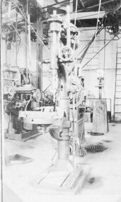
Photograph, Stawell Technical School's Large Vertical Drill, Belt driven Lathes & Electric generator plant -- 3 Photos
... Stawell Technical School's Large Vertical Drill, Belt driven Lathes & Electric generator plant -- 3 Photos...Belt driven Lathes. Electric generator plant....Belt driven Lathes. Electric generator plant. Stawell Education Stawell Technical School's Large Vertical Drill, Belt driven Lathes & Electric generator plant -- 3 Photos Photograph ...Stawell Technical School Three photos. Large Vertical Drill. Belt driven Lathes. Electric generator plant.stawell education -
 Whitehorse Historical Society Inc.
Newspaper, 'His Invention Set To Fire'
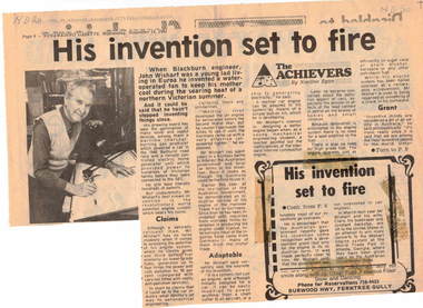
... ...electric generator...Blackburn Engineer, John Wishart, has invented gas producer used in 1940 Bathurst race, electric home generator which provided power to country properties. ...Whitehorse Historical Society Inc. 2-10 Deep Creek Road Mitcham melbourne wishart john gas producer electric generator wishart engine engineering inventions Blackburn Engineer, John Wishart, has invented gas producer used in 1940 Bathurst race, electric home generator which provided power to country properties. ...Blackburn Engineer, John Wishart, has invented gas producer used in 1940 Bathurst race, electric home generator which provided power to country properties. His best known invention is the Wishart Engine system,. Visit to Trade fair in Atlanta, Georgia in 1982wishart, john, gas producer, electric generator, wishart engine, engineering, inventions -
 Federation University Historical Collection
Instrument, General Electric Company (GEC), General Electric Company Generator used at the Ballarat Power Station at Lake Wendouree, near Ripon Street
... General Electric Company Generator used at the Ballarat Power Station at Lake Wendouree, near Ripon Street...Barker Library (top floor) Mount Helen goldfields This generator is associated with James Oddie, and possibly Henry Sutton. electricity generator ballarat power station ballarat electricity supply Early Grey generator General Electric Company Generator used at the Ballarat Power Station at Lake Wendouree, near Ripon Street Instrument General Electric Company (GEC) ...This generator is associated with James Oddie, and possibly Henry Sutton. Early Grey generatorelectricity generator, ballarat power station, ballarat electricity supply -
 Kiewa Valley Historical Society
Photos - Kiewa Hydro Electric Scheme - Dartmouth, Official S.E.C.V. photos
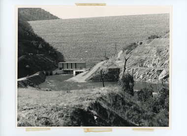
... The power station has the largest hydro-electric generator in Victoria (2022)....The power station has the largest hydro-electric generator in Victoria (2022). Official S.E.C.V. photos Photos - Kiewa Hydro Electric Scheme - Dartmouth ...Dartmouth Dam was built on the Mitta Mitta River in the 1970s. It is the highest dam in Australia (2022). It is the largest storage in Victoria (2022). It was built primarly for irrigation and urban use. The power station has the largest hydro-electric generator in Victoria (2022). -
 Wodonga & District Historical Society Inc
Domestic object - Airzone Vacuum Cleaner, 1950
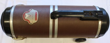
... Following the First World War, Western Electric diversified to include electric generators and wireless receivers, all still imported. ...Following the First World War, Western Electric diversified to include electric generators and wireless receivers, all still imported. ...Standard Telephones and Cables Pty Ltd was a telecommunications company that began as part of Western Electric, a telephone manufacturing company set up by Alexander Graham Bell. Following the First World War, Western Electric diversified to include electric generators and wireless receivers, all still imported. In 1925, Western Electric was sold to the International Telephone and Telegraph Company. In Australia, it became known as Standard Telephones and Cables (Australasia) They worked closely the Postmaster Generals department to set up telephone and radio networks throughout Australia. Its first factory was in Chippendale, New South Wales but ut developed to have branches in all stated of Australia. By the end of the Second World War STC was Australia's biggest manufacturer due to its critical role in producing telecommunications equipment, domestic radio receivers, telecom cables, military equipment and electron tubes. The company returned to peacetime manufacture. Rather than reduce staff it used its excess capacity to produce electric irons and other domestic appliances including vacuum cleaners and floor polishers. This model was produced at the beginning of the 1950s. It was once owned by Mr. Stiff from Stiff and Gannon, Wodonga.This item has local and national significance. It was used in a local Wodonga business and is representative of domestic appliances used in the 1950s. It also has national significance as it is an excellent example of good produced by the manufacturing industry in Australia during that period.Model 30 Airzone Vacuum Cleaner and accessories. Manufactured in AustraliaMetal logo for Airzone including engine specificationsdomestic appliances, standard telephones and cables pty ltd -
 Federation University Historical Collection
Book, Alfred P. Morgan (revised by J.W. Sim), The Boy Electrician, 1941 (exact); George G. Harrap (publisher)
... Contents include: Magnets and magnetism, static electricity, cells and batteries, cables, measuring, telegraphs, telephones, microphones, coils, transmission, transformers, generators, electric motors, radio, electric railways, lighting, circuits, gas-discharge tubes, Tesla coil, copper wire....Contents include: Magnets and magnetism, static electricity, cells and batteries, cables, measuring, telegraphs, telephones, microphones, coils, transmission, transformers, generators, electric motors, radio, electric railways, lighting, circuits, gas-discharge tubes, Tesla coil, copper wire. ...Graham Beanland, and his father, C.H. Beanland, both attended the Ballarat School of Mines.Red hard covered book of 328 pages. Contents include: Magnets and magnetism, static electricity, cells and batteries, cables, measuring, telegraphs, telephones, microphones, coils, transmission, transformers, generators, electric motors, radio, electric railways, lighting, circuits, gas-discharge tubes, Tesla coil, copper wire.Book Plate: Yallourn Technical School. Presented to G. Beanland. Second Prize Form I. Dec 1942 C.H. Beanland, pricipallighting, telephones, ammeter, magnets, magnetisn, static electricity, cells, batteries, cables, measuring, telegraphs, microphones, coils, transmission, transformers, generators, electric motors, radio, electric railways, circuits, gas dischatge tubes, tesla coil, copperiwire, morse code, galvanometer, television, ohm, x ray, xray, graham beanland, c h beanland, charles beanland, yallourn -
 Ballarat Tramway Museum
Book, Australian Commonwealth Engineering Standards Association, "Flame proof air break switches for Voltages Not Exceeding 600Volts"s", 1926-1932
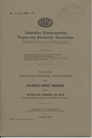
... .1 - Book - 20 pages + grey covers, side stapled, issued by the Australian Commonwealth Engineering Standards Association, Tentative Australian Standard - "Air-break knife switches and laminated brush switches for voltages not exceeding 660Volts" - C23 - 1926, August 1926" .2 - Book - 24 pages + grey covers, side stapled, issued by the Australian Commonwealth Engineering Standards Association, Tentative Australian Standard - "Flame proof air break switches for Voltages Not Exceeding 600Volts", C25-1926, October 1926. .3 - Book - 24 pages + grey covers, side stapled, issued by the Australian Commonwealth Engineering Standards Association, Tentative Australian Standard - "Flame proof air break circuit breakers for Voltages Not Exceeding 600Volts", C26-1926, October 1926. .4 - Book - 24 pages + grey covers, side stapled, issued by the Australian Commonwealth Engineering Standards Association, Tentative Australian Standard - "Totally Enclosed air-break Circuit Breakers for Voltages not exceeding 660 Volts" - C27 - 1926, September 1926. .5 - Book - 24 pages + grey covers, side stapled, issued by the Australian Commonwealth Engineering Standards Association, Tentative Australian Standard - "Totally Enclosed air-break Switches for Voltages not exceeding 660 Volts" - C28 - 1926, December 1926. .6 - Book - 24 pages + grey covers, side stapled, issued by the Australian Commonwealth Engineering Standards Association, Tentative Australian Standard "Metallic Resistance Materials for Electrical Purposes" - C29-1926, November 1926. .7 - Book - 28 pages + grey covers, side stapled, issued by the Australian Commonwealth Engineering Standards Association, Tentative Australian Standard - "Face Plate controllers and resistances for use therewith Electric Motors (DC and AC Slip ring)" - C31-1926 - December 1926. .8 - Book - 28 pages + grey covers, side stapled, issued by the Australian Commonwealth Engineering Standards Association, Australian Standard "Contactor Controllers and Resistances for use therewith Electric Motors (DC and AC Slip ring)" - C32-1926 - December 1926. .9 Book - 36 pages + grey covers, side stapled, issued by the Australian Commonwealth Engineering Standards Association, Tentative Australian Standard - "Electrical Performance of Industrial Electric Motors and Generators with class A insulation" - C34-1927, October 1927 with a green label dated September 1932 advised that the tentative standard has been endorsed as a Standard with amendment. .10 - Book - 56 pages + grey covers, side stapled, issued by the Australian Commonwealth Engineering Standards Association, Tentative Australian Standard - "Electrical Performance of Large Electric Generators and Motors - Rating permitting overloads" - C35-1927, April 1927 with a green label dated September 1932 advised that the tentative standard has been endorsed as a Standard with amendment. ...Ballarat Tramway Museum South Gardens Reserve Wendouree Parade Ballarat Ballarat goldfields Trams tramways Power Station Standards Materials Electrical Systems On top right hand corner has the date stamp of the "The Electric Supply Co. of Victoria Ltd Ballarat" .1 - Book - 20 pages + grey covers, side stapled, issued by the Australian Commonwealth Engineering Standards Association, Tentative Australian Standard - "Air-break knife switches and laminated brush switches for voltages not exceeding 660Volts" - C23 - 1926, August 1926" .2 - Book - 24 pages + grey covers, side stapled, issued by the Australian Commonwealth Engineering Standards Association, Tentative Australian Standard - "Flame proof air break switches for Voltages Not Exceeding 600Volts", C25-1926, October 1926. .3 - Book - 24 pages + grey covers, side stapled, issued by the Australian Commonwealth Engineering Standards Association, Tentative Australian Standard - "Flame proof air break circuit breakers for Voltages Not Exceeding 600Volts", C26-1926, October 1926. .4 - Book - 24 pages + grey covers, side stapled, issued by the Australian Commonwealth Engineering Standards Association, Tentative Australian Standard - "Totally Enclosed air-break Circuit Breakers for Voltages not exceeding 660 Volts" - C27 - 1926, September 1926. .5 - Book - 24 pages + grey covers, side stapled, issued by the Australian Commonwealth Engineering Standards Association, Tentative Australian Standard - "Totally Enclosed air-break Switches for Voltages not exceeding 660 Volts" - C28 - 1926, December 1926. .6 - Book - 24 pages + grey covers, side stapled, issued by the Australian Commonwealth Engineering Standards Association, Tentative Australian Standard "Metallic Resistance Materials for Electrical Purposes" - C29-1926, November 1926. .7 - Book - 28 pages + grey covers, side stapled, issued by the Australian Commonwealth Engineering Standards Association, Tentative Australian Standard - "Face Plate controllers and resistances for use therewith Electric Motors (DC and AC Slip ring)" - C31-1926 - December 1926. .8 - Book - 28 pages + grey covers, side stapled, issued by the Australian Commonwealth Engineering Standards Association, Australian Standard "Contactor Controllers and Resistances for use therewith Electric Motors (DC and AC Slip ring)" - C32-1926 - December 1926. .9 Book - 36 pages + grey covers, side stapled, issued by the Australian Commonwealth Engineering Standards Association, Tentative Australian Standard - "Electrical Performance of Industrial Electric Motors and Generators with class A insulation" - C34-1927, October 1927 with a green label dated September 1932 advised that the tentative standard has been endorsed as a Standard with amendment. .10 - Book - 56 pages + grey covers, side stapled, issued by the Australian Commonwealth Engineering Standards Association, Tentative Australian Standard - "Electrical Performance of Large Electric Generators and Motors - Rating permitting overloads" - C35-1927, April 1927 with a green label dated September 1932 advised that the tentative standard has been endorsed as a Standard with amendment. ....1 - Book - 20 pages + grey covers, side stapled, issued by the Australian Commonwealth Engineering Standards Association, Tentative Australian Standard - "Air-break knife switches and laminated brush switches for voltages not exceeding 660Volts" - C23 - 1926, August 1926" .2 - Book - 24 pages + grey covers, side stapled, issued by the Australian Commonwealth Engineering Standards Association, Tentative Australian Standard - "Flame proof air break switches for Voltages Not Exceeding 600Volts", C25-1926, October 1926. .3 - Book - 24 pages + grey covers, side stapled, issued by the Australian Commonwealth Engineering Standards Association, Tentative Australian Standard - "Flame proof air break circuit breakers for Voltages Not Exceeding 600Volts", C26-1926, October 1926. .4 - Book - 24 pages + grey covers, side stapled, issued by the Australian Commonwealth Engineering Standards Association, Tentative Australian Standard - "Totally Enclosed air-break Circuit Breakers for Voltages not exceeding 660 Volts" - C27 - 1926, September 1926. .5 - Book - 24 pages + grey covers, side stapled, issued by the Australian Commonwealth Engineering Standards Association, Tentative Australian Standard - "Totally Enclosed air-break Switches for Voltages not exceeding 660 Volts" - C28 - 1926, December 1926. .6 - Book - 24 pages + grey covers, side stapled, issued by the Australian Commonwealth Engineering Standards Association, Tentative Australian Standard "Metallic Resistance Materials for Electrical Purposes" - C29-1926, November 1926. .7 - Book - 28 pages + grey covers, side stapled, issued by the Australian Commonwealth Engineering Standards Association, Tentative Australian Standard - "Face Plate controllers and resistances for use therewith Electric Motors (DC and AC Slip ring)" - C31-1926 - December 1926. .8 - Book - 28 pages + grey covers, side stapled, issued by the Australian Commonwealth Engineering Standards Association, Australian Standard "Contactor Controllers and Resistances for use therewith Electric Motors (DC and AC Slip ring)" - C32-1926 - December 1926. .9 Book - 36 pages + grey covers, side stapled, issued by the Australian Commonwealth Engineering Standards Association, Tentative Australian Standard - "Electrical Performance of Industrial Electric Motors and Generators with class A insulation" - C34-1927, October 1927 with a green label dated September 1932 advised that the tentative standard has been endorsed as a Standard with amendment. .10 - Book - 56 pages + grey covers, side stapled, issued by the Australian Commonwealth Engineering Standards Association, Tentative Australian Standard - "Electrical Performance of Large Electric Generators and Motors - Rating permitting overloads" - C35-1927, April 1927 with a green label dated September 1932 advised that the tentative standard has been endorsed as a Standard with amendment. On top right hand corner has the date stamp of the "The Electric Supply Co. of Victoria Ltd Ballarat" trams, tramways, power station, standards, materials, electrical systems -
 Ballarat Tramway Museum
Book, Australian Commonwealth Engineering Standards Association, "Electrical Performance of Large Electric Generators and Motors - Continuous Maximum Rating", "Pressboard for Electrical Purposes", "Hard Drawn copper stranded circular conductors for overhead power transmission purposes", "for Indicating Ammeters, Voltmeters, wattmeters, frequency and power factor meters", "Instrument Transformers", "Liquid Starters for Electric Motors", "Star Delta switch starters for Electric Motors", "Multiple switch starters for Electric Motors", 1926-1933
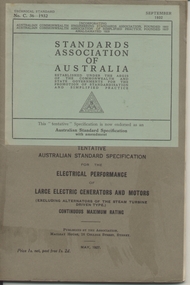
... .1 - Book - 56 pages + grey covers, side stapled, issued by the Australian Commonwealth Engineering Standards Association, Tentative Australian Standard - "Electrical Performance of Large Electric Generators and Motors - Continuous Maximum Rating" - C36-1927, May 1927 with a green label dated September 1932 advised that the tentative standard has been endorsed as a Standard with amendment. .2 - Book - 48 pages + grey covers, side stapled, issued by the Australian Commonwealth Engineering Standards Association, Tentative Australian Standard - "Electrical Performance of Alternators of the Steam Driven Type" - C38-1927 - December 1927 with a green label dated September 1932 advised that the tentative standard has been endorsed as a Standard with amendment. .3 - Book - 32 pages + grey covers, side stapled, issued by the Australian Commonwealth Engineering Standards Association, Tentative Australian Standard - "Electricity Meters" C39-1927, August 1927. .4 - Book - 28 pages + grey covers, side stapled, issued by the Australian Commonwealth Engineering Standards Association, Tentative Australian Standard - "Pressboard for Electrical Purposes" - C40-1927, January 1927. .5 - Book - 24 pages + grey covers, side stapled, issued by the Australian Commonwealth Engineering Standards Association, Tentative Australian Standard - "Hard Drawn copper stranded circular conductors for overhead power transmission purposes" C41-1930, August 1927, with a green label dated October 1932 advised that the tentative standard has been endorsed as a Standard with amendment. .6 - Book - 48 pages + grey covers, side stapled, issued by the Australian Commonwealth Engineering Standards Association, Tentative Australian Standard "for Indicating Ammeters, Voltmeters, wattmeters, frequency and power factor meters" - C42-1927 - December 1927, with a green label dated October 1932 advised that the tentative standard has been endorsed as a Standard with amendment. .7 - Book - 32 pages + grey covers, side stapled, issued by the Australian Commonwealth Engineering Standards Association, Tentative Australian Standard - "Instrument Transformers" - C45-1928, June 1928. .8 - Book - 28 pages + grey covers, side stapled, issued by the Australian Commonwealth Engineering Standards Association, Australian Standard "Liquid Starters for Electric Motors" C46-1927, December 1927. .9 - Book - 20 pages + grey covers, side stapled, issued by the Australian Commonwealth Engineering Standards Association, Australian Standard "Star Delta switch starters for Electric Motors" C47-1927, December 1927. .10 - Book - 24 pages + grey covers, side stapled, issued by the Australian Commonwealth Engineering Standards Association, Australian Standard "Multiple switch starters for Electric Motors" C48-1927, December 1927. ..."Electrical Performance of Large Electric Generators and Motors - Continuous Maximum Rating", "Pressboard for Electrical Purposes", "Hard Drawn copper stranded circular conductors for overhead power transmission purposes", "for Indicating Ammeters, Voltmeters, wattmeters, frequency and power factor meters", "Instrument Transformers", "Liquid Starters for Electric Motors", "Star Delta switch starters for Electric Motors", "Multiple switch starters for Electric Motors" Book Australian Commonwealth Engineering Standards Association ....1 - Book - 56 pages + grey covers, side stapled, issued by the Australian Commonwealth Engineering Standards Association, Tentative Australian Standard - "Electrical Performance of Large Electric Generators and Motors - Continuous Maximum Rating" - C36-1927, May 1927 with a green label dated September 1932 advised that the tentative standard has been endorsed as a Standard with amendment. .2 - Book - 48 pages + grey covers, side stapled, issued by the Australian Commonwealth Engineering Standards Association, Tentative Australian Standard - "Electrical Performance of Alternators of the Steam Driven Type" - C38-1927 - December 1927 with a green label dated September 1932 advised that the tentative standard has been endorsed as a Standard with amendment. .3 - Book - 32 pages + grey covers, side stapled, issued by the Australian Commonwealth Engineering Standards Association, Tentative Australian Standard - "Electricity Meters" C39-1927, August 1927. .4 - Book - 28 pages + grey covers, side stapled, issued by the Australian Commonwealth Engineering Standards Association, Tentative Australian Standard - "Pressboard for Electrical Purposes" - C40-1927, January 1927. .5 - Book - 24 pages + grey covers, side stapled, issued by the Australian Commonwealth Engineering Standards Association, Tentative Australian Standard - "Hard Drawn copper stranded circular conductors for overhead power transmission purposes" C41-1930, August 1927, with a green label dated October 1932 advised that the tentative standard has been endorsed as a Standard with amendment. .6 - Book - 48 pages + grey covers, side stapled, issued by the Australian Commonwealth Engineering Standards Association, Tentative Australian Standard "for Indicating Ammeters, Voltmeters, wattmeters, frequency and power factor meters" - C42-1927 - December 1927, with a green label dated October 1932 advised that the tentative standard has been endorsed as a Standard with amendment. .7 - Book - 32 pages + grey covers, side stapled, issued by the Australian Commonwealth Engineering Standards Association, Tentative Australian Standard - "Instrument Transformers" - C45-1928, June 1928. .8 - Book - 28 pages + grey covers, side stapled, issued by the Australian Commonwealth Engineering Standards Association, Australian Standard "Liquid Starters for Electric Motors" C46-1927, December 1927. .9 - Book - 20 pages + grey covers, side stapled, issued by the Australian Commonwealth Engineering Standards Association, Australian Standard "Star Delta switch starters for Electric Motors" C47-1927, December 1927. .10 - Book - 24 pages + grey covers, side stapled, issued by the Australian Commonwealth Engineering Standards Association, Australian Standard "Multiple switch starters for Electric Motors" C48-1927, December 1927. On top right hand corner has the date stamp of the "The Electric Supply Co. of Victoria Ltd Ballarat" trams, tramways, power station, standards, materials, electrical systems -
 Halls Gap & Grampians Historical Society
Newspaper - Photocopy
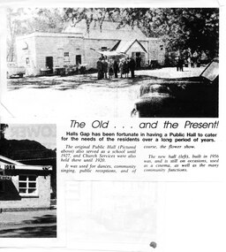
... Estimated cost of the building was around 8,000 pounds, and when finally finished it was just slightly over, but bank charges and interest took it to well over 9,000 pounds. An electric light generator was included and lighting installed. ...Estimated cost of the building was around 8,000 pounds, and when finally finished it was just slightly over, but bank charges and interest took it to well over 9,000 pounds. An electric light generator was included and lighting installed. ...The article shows a photo of the original Hall's Gap Hall and the (then) new Hall, which was built in 1956. The copy has been scanned as two separate images (because it was too large for the scanner). the second image is stored under "Additional Images". HISTORY OF HALL'S GAP HALL: No village, no matter how small, could possibly survive without a public meeting place, and Hall's Gap was no exception, even in 1899-1900. Actually it was the locals of Stony Creek village, as Hall's Gap was known for a short time, who decided to hold a meeting to find out how much interest there was in building a town hall! They soon found out that support was overwhelming, as can be seen by the fact that 14 gentlemen nominated for a position on the committee of four! Several motions were moved at that meeting, mainly with reference to the materials to be used, for instance that no "wattle and daub", but rather slabs of bark and local bush logs be used. The walls were to be constructed of slabs, 6 feet long, 9 inches wide and two inches thick. Uprights were to be 9 feet high and at least 9 inches thick. Sheets of bark, all 32 of them, had to be 8 feet by 8 feet. Tenders for the building materials were called on 9 March 1899 and, 21 days later, McKeon Brothers won the right to supply all the material for the princely sum of 4 pounds 10 shillings. The size of the hall was to be 20 feet by 10 feet. The first hall served the community well for the next thirteen years, being regularly used as a place of entertainment and religious worship. The growing community soon realised the need for a larger venue, with better facilities, so once again the townsfolk rallied to raise funds for a new hall, realising their dream around 1913. In 1921 a schoolteacher was provided by the education department but as there was no school building she was expected to use the hall. Mainly lessons were held in the kitchen as it was much warmer than the hall itself, and it was not unusual for up to twenty children to be taught, ranging in age from 5 to 14 years. It was not until 1928 that an official school was built. 1955-56 were years of great excitement. The Progress Association was in charge of deciding the format for the new hall, and there were many rowdy meetings beforehand. Some members had much more vision than others, and to some the amount of money required seemed astronomical. Two hall committee members resigned over differences of opinion but amazingly it all came together in the end, albeit at a greater cost than had been anticipated. There is only one record of a grant being made for the building,1500 pounds, and it came for the Minister of Public Works. Estimated cost of the building was around 8,000 pounds, and when finally finished it was just slightly over, but bank charges and interest took it to well over 9,000 pounds. An electric light generator was included and lighting installed. The SEC electricity was connected in 1962.A copy of a newspaper article entitled 'The Old . . . and the Present!', which includes two photographs.buildings, halls -
 Eltham District Historical Society Inc
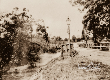
Photograph, Diamond Creek Bridge, Eltham North, c.1920
... By the end of World War I, local Victorian councils rapidly phased out acetylene infrastructure in favour of safer, independent electric powerhouse generators. In the context of Eltham's local history, the Eltham Shire and surrounding Yarra Valley region actively relied on carbide streetlamps and kerosene lighting during the early 20th century before the expansion of the Melbourne electric grid. ...By the end of World War I, local Victorian councils rapidly phased out acetylene infrastructure in favour of safer, independent electric powerhouse generators. In the context of Eltham's local history, the Eltham Shire and surrounding Yarra Valley region actively relied on carbide streetlamps and kerosene lighting during the early 20th century before the expansion of the Melbourne electric grid. ...View looking east across the Glen Park Bridge and the railway crossing towards Main Road circa 1920. The bridge was originally built as a replacement for an older private bridge built by a man named Foley around 1880. In 1911 Heidelberg and Eltham agreed to share the costs to build a new bridge (the Diamond Creek was the border between the two). Construction began in June 1915 and it was officially opened by Cr. Taylor on Cup Day, November 1915. This photo, dated around 1920, is of the Glen Park Bridge crossing over the Diamond Creek about 50 metres north of the present-day Wattletree tree Road Bridge. Glen Park Road intersected Main Rain Road along an alignment following present day Coleman Cresent. In this this picture we see the narrow wooden bridge over a high flowing Diamond Creek at Glen Park, now Eltham North. In the background is a railway crossing sign. There is a self-contained carbide streetlamp situated in front of the bridge. In the early 1900s, carbide (acetylene gas) streetlamps emerged as a lighting technology for regional towns across Victoria, Australia, before municipal electricity grids were widely established. During the late Victorian and early Edwardian eras, major hubs like Melbourne relied on centralized coal-gas infrastructure. However, small regional Victorian shires lacked the funds or population density to build large gasworks. When the commercial production of calcium carbide became viable around 1900, it offered a quantum leap in brightness over traditional kerosene streetlamps. Acetylene gas burned with an intense, crisp white flame—significantly brighter than oil or candles. Many rural towns used self-contained lampposts. A lamplighter had to climb each post daily to manually place calcium carbide pellets in a lower chamber and fill an upper chamber with water. The water dripped onto the carbide, producing acetylene gas to feed the burner. Lamplighters carefully measured the fuel amounts so the chemical reaction would naturally exhaust itself and "turn off" around midnight. While carbide streetlights provided unparalleled visibility for early motorists, cyclists, and pedestrians, they were incredibly labour-intensive and inherently volatile. The gas was highly explosive, prone to leaks, and left behind a pungent, sulphur-like odour. By the end of World War I, local Victorian councils rapidly phased out acetylene infrastructure in favour of safer, independent electric powerhouse generators. In the context of Eltham's local history, the Eltham Shire and surrounding Yarra Valley region actively relied on carbide streetlamps and kerosene lighting during the early 20th century before the expansion of the Melbourne electric grid. Eltham was an outer-rural, heavily timbered farming and orchard district at the turn of the century, it faced unique civic infrastructure challenges. In rural Eltham, early streetlamps were exceptionally sparse. The community relied heavily on "innkeeper laws" which dictated local hotels—such as the historic Eltham Hotel—were legally required to keep external oil, kerosene, or acetylene lamps burning through the night to illuminate the main roads for travellers and coaches. The volatile carbide and kerosene lamps on Eltham's main thoroughfares were progressively phased out during the 1920s. The district steadily transitioned to electricity, which allowed for developments like the installation of modern electrical wiring at the local fire station on Arthur Street by 1928. The Glen Park Bridge was a low structure and subject to flooding readily. In 1959 Eltham Council erected a new crossing over the Diamond Creek and realigned the road to the present-day Wattletree Road Bridge. Construction was not fully complete when on Sunday, 20 September 1959, heavy flooding occurred in the stream and at 3:53 pm the old bridge was washed away forever. - Research by Peter Pidgeon, EDHS, June 2026Photograph copy eltham north, wattletree road, coleman crescent, bridges, diamond creek (creek), bridge, carbide streetlamp, floodwater, glen park bridge, street lamp, glen park road, glen park estate -
 Kiewa Valley Historical Society
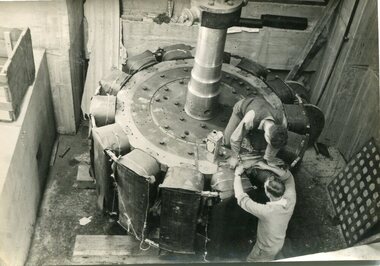
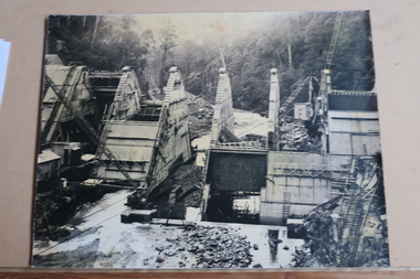
Photographs – SECV – Clover Power Station
... SECV; Kiewa Hydro Electric Scheme; Clover Power Station; Junction Dam; Bogong On the back- each photograph has a handwritten reference number starting with K and the date stamped or written Set of 21 black and white photographs taken by the official SECV photographer who gave each photo a number prefixed by K (for Kiewa) K1367- 19 Nov 1943 The rotor for the generator K1368- 19 Nov 1943 Base of the generator K1377- 2 Dec 1943 Generator under construction K1380- 2 Dec 1943 Power Station under construction K1381- 2 Dec 1943 Generator being assembled K1386- 3 Dec 1943 Part of the generator K1389- 30 Dec 1943 Inlet pipe work K1391- 30 Dec 1943 Inside the power station K1392- 30 Dec 1943 Inlet pipe work K1396- 27 Jan 1944 Equipment in the power station K1410- 4 FGeb 1944 Unpacking equipment for the power station K1422- 16 Feb 1944 Generator being assembled K1425- 22 Feb 1944 Water way – power station K1433- no date Generator being assembled K1434- 3 Mar 1944 Constr5ucting the power station K1448- no date Generator inside the power station K1450- 17 Mar 1944 Clover Power station K1452- 17 Mar 1944 Looking down on the valve-water release from the power station K1456- 22 Mar 1944 ‘half Travel Opening- No 1 Relief Valve’ Overflow from the power station K1458- 22 Mar 1944 Outlet from the power station K1462- 22 Mar 1944 Inside the power station Photographs – SECV – Clover Power Station ...The Junction Dam and Clover Dam Power Station, stages of the Kiewa Hydro-Electric Scheme, were needed to meet the increased power demands of the wartime industry in Victoria. Clover added 26 megawatts to the grid. Junction Dam was completed and ready to hold water by September 1943, but was emptied in December 1943 and not filled again until May 1944. Construction of Clover Power Station commenced in July 1941 and both turbines were in service by May 1945.Clover Power Station and Junction Dam were part of the Kiewa Hydro Electric Scheme constructed by the State Electricity Commission of Victoria.Set of 21 black and white photographs taken by the official SECV photographer who gave each photo a number prefixed by K (for Kiewa) K1367- 19 Nov 1943 The rotor for the generator K1368- 19 Nov 1943 Base of the generator K1377- 2 Dec 1943 Generator under construction K1380- 2 Dec 1943 Power Station under construction K1381- 2 Dec 1943 Generator being assembled K1386- 3 Dec 1943 Part of the generator K1389- 30 Dec 1943 Inlet pipe work K1391- 30 Dec 1943 Inside the power station K1392- 30 Dec 1943 Inlet pipe work K1396- 27 Jan 1944 Equipment in the power station K1410- 4 FGeb 1944 Unpacking equipment for the power station K1422- 16 Feb 1944 Generator being assembled K1425- 22 Feb 1944 Water way – power station K1433- no date Generator being assembled K1434- 3 Mar 1944 Constr5ucting the power station K1448- no date Generator inside the power station K1450- 17 Mar 1944 Clover Power station K1452- 17 Mar 1944 Looking down on the valve-water release from the power station K1456- 22 Mar 1944 ‘half Travel Opening- No 1 Relief Valve’ Overflow from the power station K1458- 22 Mar 1944 Outlet from the power station K1462- 22 Mar 1944 Inside the power station On the back- each photograph has a handwritten reference number starting with K and the date stamped or writtensecv; kiewa hydro electric scheme; clover power station; junction dam; bogong -
 Kiewa Valley Historical Society
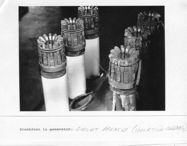
Photograph - Folder of Photographs – Photocopied set of black and white photographs (pages 39 - 48) from the display folder put together by KVHS to document life on the Kiewa Valley Hydro-electric Scheme
... Mount Beauty, and to a lesser extent Bogong, are among these places. secv; kiewa hydro electric scheme; construction area; power stations; reservoirs; aqueduct; mt beauty; bogong 1-Breakdown in (generator) Circuit Breaker (Isolating Contacts) Handwritten underneath (This is not a picture of any part of a generator. ...Although the Kiewa Hydro-Electric Scheme was first proposed in 1911, construction did not commence until 1938. As part of the push to cut electricity costs and diversify supply, the Victorian Government (circa 1930) initiated the conversion from primarily brown coal supply to hydro – electricity. Field investigations during the 1940’s resulted in a new proposal for a scheme that had more than double the capacity of the 1938 scheme. The Kiewa Hydroelectric Scheme became the largest scheme of its kind in the State Of Victoria and the second largest scheme in Australia. The number of personnel involved in the planning and construction of the scheme increased dramatically. During the late 1940’s, most activity centered around the construction of the West Kiewa Power Station, Rocky Valley Reservoir, McKay Creek Power Station and the Bogong Creek Aqueduct.A common thread across all the larger hydro scheme constructions was the need for workers, both qualified and unqualified who came from around the world seeking a new life for themselves and their families. New accommodation and facilities were required for the army of workers engaged in construction in often remote and wild areas. The SEC had a high demand for timber, and set up the first of a number of sawmills at Bogong Creek in 1939 and set up the first hardwood logging in the headwaters of the Kiewa River. These new ‘towns’ such as Mt Beauty and Bogong, survived, serving the needs of operational personnel and their families, and expanding with growth of new industries. Mount Beauty, and to a lesser extent Bogong, are among these places. Large A3 size spiral bound display folder containing photocopied black and white photographs of various aspects of the early days of the Kiewa Valley Hydro-electric scheme including equipment, various work sites and photographs of workers and their families. 1-Breakdown in Circuit Breaker (Isolating Contacts) 2-Big Hill Bench- Site of No 5 Devlopment 3-No 1 Power Station 4-No 1 Pipeline, Anchor No 8 5-Push Dozing-RD8 Tractor 6- Tractor and driver at work 7- Workmen in unnamed tunnel 8- Front page of Journal of SECV Vol 15. Photograph of No 1 pipeline viewed from McKay Portal 9-Rocky Valley Dam Core Wall 10-Workmen working inside tunnel loading rocks into a rail truck. 1-Breakdown in (generator) Circuit Breaker (Isolating Contacts) Handwritten underneath (This is not a picture of any part of a generator. It is a circuit breaker Signed Ron White Ron was the Principal Hydro Engineer of the SEC Kiewa Scheme Page number 39 2-Big Hill Bench – Site of No. 5 Development (abandoned) Page number 40 3-No 1 Power Station Page number 41 4-No. 1 Pipeline, Anchor No. 8 Page number 42 5-Push Dozing – RD8 Tractor, 12 cubic yard Carryall and FD Cletrac Tractor Page number 43 6-No marking Page number 44 7-No marking Page number 45 8-Journal of State Electricity Commission of Victoria SEC Vol 15 No… April-May, 19… No 1 Pipeline-A view from McKay Portal G Hempenstall and D Sutton stiffening pipe section for transport during construction (….indicates missing text) Page Number 46 9-Rocky Valley Dam Core Wall Page number 47 10-No markings Page number 48 secv; kiewa hydro electric scheme; construction area; power stations; reservoirs; aqueduct; mt beauty; bogong -
 Kiewa Valley Historical Society
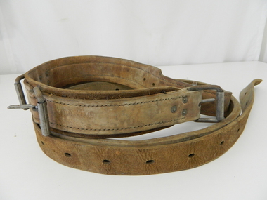
Belt Linesman Pole, circa mid to late 1900's
... electric chair". The maintenance of the linesman's belt was his responsibility (keeping it clean and in "good" condition). Labour laws change this initial responsibility, from the linesman, to the employer. Climbing pegs were installed on higher poles that extended beyond the reach of ladders. kiewa hydro electricity scheme victorian state electricity commission relays generators electrical pole maintenance This thick leather linesman belt is made from two lengths of heavy lengths of leather straps sewn together to make up 80% of the belt. ...This linesman belt was used under the 1947 Electricity Regulations and before tighter Occupation and Health regulations (late 1990's early 2000's) were introduced that mechanical lifting platforms(wherever possible) replaced the belt up the pole method.The safety concern was that it required that tools needed by the linesman had to be placed in a large canvas bag and attached to the belt (extra weight) then the linesman had to climb the ladder. Ladders had to be at the correct angle and not able to "slip" from their initial footings. A full harness and a secondary fall belt is now mandatory for pole linesmen. The safety of fellow workers could be compromised if they were required to assist or recover the first linesman if needed. In 2006 an additional 269 registered lineworkers were employed. Please note that the terminology of linesman has become unisex. The linesman's belt enabled the linesman to place his feet against the pole adjust the belt (if needed) and lean back securely allowing both hands to be free to work with. This linesman belt is very significant to the Kiewa Valley due to the numerous poles and high voltage overhead power structures that needed maintenance for the extensive "mushroom" installation of electrical power polls(wood and metal). On high poles (steel) climbing pegs were welded on, however in the Alpine areas snow in winter caused an OH&S problem which were hard to overcome. The safety of a linesman when maintenance of electricity line on poles can be highlighted by the New Zealand linesman who survived an 11,000 volt shock when carrying out maintenance. For the record 11,000 volts is four times more powerful than execution by "the electric chair". The maintenance of the linesman's belt was his responsibility (keeping it clean and in "good" condition). Labour laws change this initial responsibility, from the linesman, to the employer. Climbing pegs were installed on higher poles that extended beyond the reach of ladders.This thick leather linesman belt is made from two lengths of heavy lengths of leather straps sewn together to make up 80% of the belt. The remaining 20% is "the belt tonge" which has eleven holes for three (solid steel tang) buckle connections.kiewa hydro electricity scheme, victorian state electricity commission, relays, generators, electrical pole maintenance -
 Kiewa Valley Historical Society
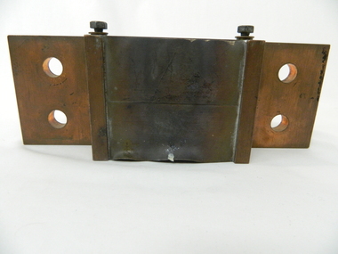
Electric Current Shunt
... kiewa hydro electric scheme. secv. hydro generator. victorian electricity grid...generator control metering system. It reduces the large current to a small voltage. Historical: This equipment represents a major construction and ongoing operational industry dealing with the supply of hydro electricity to Victoria. kiewa hydro electric scheme. secv. hydro generator. victorian electricity grid power station. electricity. resistor Screwed in metal plaque: Deriv. 1662691 / OHM 0.0000833 / AMP 1200 on the side of the cube above a shelf and on the opposite shelf: ALTO ----> (also a metal plaque screwed on). ...This shunt is a type of resistor built of copper and designed to carry a current. It was part of the Hydro generator control metering system. It reduces the large current to a small voltage.Historical: This equipment represents a major construction and ongoing operational industry dealing with the supply of hydro electricity to Victoria.Made of copper the shunt has a middle cube with 12 sheets of copper, 5mm apart formed like shelves. On either side of the cube are two shelves coming out from the middle. Both have 2 hollow circles 17.5mm in diameter 25 mm apart in the middle. At the Join of the 'shelves' and cube is a screw on each side.Screwed in metal plaque: Deriv. 1662691 / OHM 0.0000833 / AMP 1200 on the side of the cube above a shelf and on the opposite shelf: ALTO ----> (also a metal plaque screwed on). kiewa hydro electric scheme. secv. hydro generator. victorian electricity grid, power station. electricity., resistor -
 Kiewa Valley Historical Society
Photos: SECV Construction
... Electric Scheme: 1. Clover Dam Construction 2. Clover Dam Construction suspended on a crane 3. Power Station Clover Dam 4. Hauling tunnel muck. Tunnel "Ruston" locomotive on rail entrance.5. McKay Power Station 6. Connecting the headrace pipe to turbo turbines - large pipes and workman (double pipe) bifurcate pipes. 7. Installing a generator...Electric Scheme: 1. Clover Dam Construction 2. Clover Dam Construction suspended on a crane 3. Power Station Clover Dam 4. Hauling tunnel muck. Tunnel "Ruston" locomotive on rail entrance.5. McKay Power Station 6. Connecting the headrace pipe to turbo turbines - large pipes and workman (double pipe) bifurcate pipes. 7. Installing a generator ...The SECV constructed the Kiewa Hydro Electric Scheme from the late 1940s to the early 1960s. Dams, Power Stations, towns, etc. were built during this timeThese photos show a lot of detail of the work involved in constructing large structures eg. power stations, dams etc. Also they give an insight into safety eg. clothing etc. at the time. These photos were displayed on the walls of the hotel when the building was the SEC Workmans Club x12 Most of them framed. Large black and white photos of construction of the Kiewa Hydro Electric Scheme: 1. Clover Dam Construction 2. Clover Dam Construction suspended on a crane 3. Power Station Clover Dam 4. Hauling tunnel muck. Tunnel "Ruston" locomotive on rail entrance.5. McKay Power Station 6. Connecting the headrace pipe to turbo turbines - large pipes and workman (double pipe) bifurcate pipes. 7. Installing a generator - seven workmen with hard hats (assembling). 8. V3536 number plate - fire fighting truck - filling up with water. 9. 1939 after bushfire. 10. West Kiewa Power Station - labelled. 11. Lining the portal of a tunnel 12. Camp and offices on left, tunnel entrance on right.khes, construction of khes -
 Kiewa Valley Historical Society
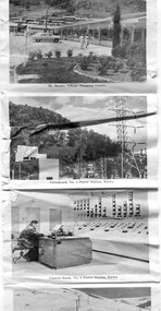
Postcard - Mt Beauty and the Kiewa Hydro Electric Scheme
... Tourism in the Kiewa Valley especially at Mt Beauty and the Bogong High Plains along with the Kiewa Hydro Electric Scheme became very popular and an important industry. transmission line Power station generators Mt Beauty turbines Junction Dam switchyard Rocky Valley Control room Fold out b & w postcard with 12 photos back to back. ...SECV constructed the Kiewa Hydro Electric Scheme including the township of Mt Beauty. The area became a popular tourist destination.Tourism in the Kiewa Valley especially at Mt Beauty and the Bogong High Plains along with the Kiewa Hydro Electric Scheme became very popular and an important industry.Fold out b & w postcard with 12 photos back to back. All with a title. Kate 1950s 1. High Voltage Transmission Line, showing Mount Beauty Township 2. Clover Dam Reservoir, Kiewa 3. No. 3 Power Station, Kiewa 4. Generators, No. 3 Power Station 5. Turbines, No. 4 Power Station, Kiewa 6. junction Dam, Bogong 7. Mt Beauty Village Shopping Centre 8. Switchyard, No. 4 Power Station, Kiewa 9. Control Room, No. 4 Power Station, Kiewa 10. Winter Scene at Rocky Valley on the Bogong High Plains 11. Water Channel, Mt Bogong in Background 12. Mt Beauty Township, Kiewa Valleytransmission line, power station, generators, mt beauty, turbines, junction dam, switchyard, rocky valley, control room -
 Kiewa Valley Historical Society
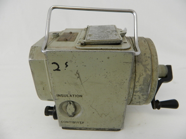
Tester Direct Current, mid 1900's
... Generators are at Dartmouth, Mackay, Clover, West Kiewa, Yarrawonga, Cain Curran and three Power Stations in the Thornton area. sec vic kiewa hydro scheme alternate energy supplies alpine feasibility studies temperature rainfall Manufacturer's details on top side "MEG" underneath "INSULATION AND CONTINUITY TESTER" below this "constant 500 VOLT pressure" below this "REGISTERED MEG MEGGER TRADE MARK" below this "REG DESIGN NO. 690326" below this "UNITED KINGDOM PATENT Nos. 193746, 197178, 198182, 202062, 202398, 204649, 350715" below this "SUPPLIED BY THE GENERAL ELECTRIC Co. ...This tester was used between 1950 and 1980's. As part of the Occupation, Health and Safety requirements, equipment used to monitor the performance of electricity producing generators, regularly, hand held testers were used to check the insulation and the "earth" pin were up the the required operational levels. As the generators and their ancillary monitoring equipment was spread over a large area and cumbersome to service small hand held devices were required. These had to always be safe for the user to operate. A selected range of high quality meters were recalibrated every two years in the Meter and Calibration Laboratory at Yarraville(near Melbourne) This meter is very significant to The Kiewa Hydro Electricity Scheme because it was an integral part of maintaining the electricity producing water driven generators of the power stations. The reason why this meter was so essential is that provided the safety check on equipment used to monitor each Hydro Generator that they were complying within the grid network parameters. Grid parameters are set so that if there is an electrical fault on the system, that fault can be attended to with a very small change in the output stability of each generator. It is essential that the voltage of the network remain within the set limits. Generators are at Dartmouth, Mackay, Clover, West Kiewa, Yarrawonga, Cain Curran and three Power Stations in the Thornton area.This hand driven current generator produces 500 volts by winding the handle(on funnel curved side) to keep the voltage constant(one minute per test). The whole body is made from caste aluminium. One of the functions of this meter is to test the isolation resistance of any equipment being tested. This is to see if that equipment is safe to handle(no electrical shocks). The second function is to test the earth pin of any portable electrical equipment. The turn key on one side can direct which function is required(marked insulation or continuity). On the top side(enclosed in a glass fronted marked scale) is a continuity scale(top) and an insulation scale(bottom). This is covered , when not in use by "flip up" lid with manufacturer's details and name of the instrument. Opposite the winder are two screw tight knobs. One marked earth(left side) and one marked line(right side). On the top and next to the glass windowed scales in a post manufacture SEC Vic equipment equipment ID number. For carrying purposes there is chromed steel (fold together) handle.The bottom of the unit has two metal "feet" 150mm long by 114mm wideManufacturer's details on top side "MEG" underneath "INSULATION AND CONTINUITY TESTER" below this "constant 500 VOLT pressure" below this "REGISTERED MEG MEGGER TRADE MARK" below this "REG DESIGN NO. 690326" below this "UNITED KINGDOM PATENT Nos. 193746, 197178, 198182, 202062, 202398, 204649, 350715" below this "SUPPLIED BY THE GENERAL ELECTRIC Co. Ltd OF ENGLAND" below this "MAGNET HOUSE, KINGSWAY LONDON W.C.2" 'sec vic kiewa hydro scheme, alternate energy supplies, alpine feasibility studies temperature, rainfall -
 Bendigo Historical Society Inc.
Slide - RALPH BIRRELL COLLECTION: EIG SCHOOL, c1966
... Applied Science. A generator coupled with an electric motor. work shop fitted draws...Bendigo Institute of Technology, Engineering School, Applied Science. A generator coupled with an electric motor. The work shop is fitted with draws on the left of the room....Bendigo Institute of Technology Engineering School Applied Science. A generator coupled with an electric motor. work shop fitted draws Perutz EIG School - Ralph Birrell Collection. - Construction of Latrobe Uni. ...EIG School - Ralph Birrell Collection. - Construction of Latrobe Uni. C1966. Bendigo Institute of Technology, Engineering School, Applied Science. A generator coupled with an electric motor. The work shop is fitted with draws on the left of the room.Perutzeducation, tertiary, latrobe university bendigo, eig school - ralph birrell collection. - construction of latrobe uni. c1966. bendigo institute of technology, engineering school, applied science. a generator coupled with an electric motor. work shop fitted draws -
 Bendigo Historical Society Inc.
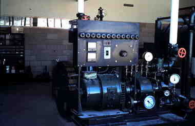
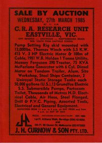
Document - IAN DYETT COLLECTION: AUCTION CATALOGUE - C.R.A. RESEARCH UNIT - EASTVILLE
... Thomas Winch with 5.5 K.W. 415 V. 3 HP Electric Motor & 100m of Cable, 1981 W.B. Holden 1 Tonne Utility, Massey Ferguson 290 Tractor, 75 KVA McFarlane Generator with 6 Cyl. ...Thomas Winch with 5.5 K.W. 415 V. 3 HP Electric Motor & 100m of Cable, 1981 W.B. Holden 1 Tonne Utility, Massey Ferguson 290 Tractor, 75 KVA McFarlane Generator with 6 Cyl. ...Red covered auction catalogue with black printing for a sale at C.R.A. Research Unit, Eastville, Vic on 27th March 1985. For sale was Pump Setting Rig skid mounted with 12,000 lbs. Thomas Winch with 5.5 K.W. 415 V. 3 HP Electric Motor & 100m of Cable, 1981 W.B. Holden 1 Tonne Utility, Massey Ferguson 290 Tractor, 75 KVA McFarlane Generator with 6 Cyl. Diesel Motor on Tandem Trailer, Alum. Site Workshop, Steel Ships Container, 2 Uniroyal Static Storage Tanks each 50,000 gallons (U.S.), 13 Groundfos Electric S.S. Submersible Pumps, Portacom Toilet, Thousands of Metres H.D. Electrical Cable, Air Hose, Steel Flanged, Drill & P.V.C. Piping, Assorted Tools, Electrical and General Equipment. J. H. Curnow & Son Pty. Ltd. Were the auctioneers.business, auctioneers, j h curnow & son pty ltd, ian dyett collection - auction catalogue - c.r.a. research unit - eastville vic, j h curnow & son pty ltd, f c dyett, i m dyett, n f dyett, bolton bros pty ltd print -
 Federation University Historical Collection
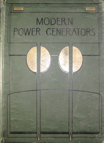
Book, Modern Power Generators: steam electric and internal-combustion and their application to present-day requirements, 1908 (exact)
... 'Modern Power Generators' deals with the production of Steam, Electric and Gas power....Modern Power Generators: steam electric and internal-combustion and their application to present-day requirements. ...James Weir graduated from Strathclyde University with a degree in Economics. James gained extensive industrial experience with anengineering group called the 'Weir Group". He then became a Director at Hambros Advanced Technology Trust. In 1990, James was the Founder and Director at Duke Street Capital. He speaks English and French. A large green cloth hardcover book with gold and black decorations on front cover. Title is engraved in black on front cover and in gilt on spine. Title is printed in black and red on title-page. Volume 1 with illustrations in b/w with diagrams and a series of coloured composite sectional models. 'Modern Power Generators' deals with the production of Steam, Electric and Gas power.boiler, steam, james weir french, engine, air brake, induction motor, internal combustion, turbine, locomotive, otto, diesel -
 Federation University Historical Collection
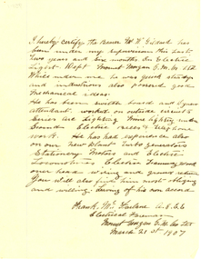
Letter - Correspondence, Norman F. White, Correspondence on Mount Morgan Gold-mining Company, Limited Letterhead, 1907, 22/03/1907
... He has been switch board and Dynamo attendant worked on outside circuits series are Lighting Mine Lighting under Ground Electric Bells and Telephone work. He has had experience also on our new plant turbo generators Stationary Motors and Electric Locomotives Electric Tramway Work over head wiring and ground return you will also find him most obliging and willing. ...He has been switch board and Dynamo attendant worked on outside circuits series are Lighting Mine Lighting under Ground Electric Bells and Telephone work. He has had experience also on our new plant turbo generators Stationary Motors and Electric Locomotives Electric Tramway Work over head wiring and ground return you will also find him most obliging and willing. ...Typed letter on Mount Morgan Gold-mining Company, Limited Letterhead relating to staffmember W. Gildard who worked in the Electrical Department at Mount Morgan. The letter is signed by Norman F. White..1) I hereby certify the Bearer Mr W. Gildard has been under my supervision this last two years and six months in Electric Light Dept Mount Morgan G.M.Co. Ltd While under me he was quick steady and industrious also possessed good mechanical ideas. He has been switch board and Dynamo attendant worked on outside circuits series are Lighting Mine Lighting under Ground Electric Bells and Telephone work. He has had experience also on our new plant turbo generators Stationary Motors and Electric Locomotives Electric Tramway Work over head wiring and ground return you will also find him most obliging and willing. Leaving of his own accord. Frank McFarlane A.G.E.E. Electric Foreman Mount Morgan G.M. Co. Ltd march 21st 1907ballarat school of mines, mount morgan gold-mining company, mount morgan, norman f. white, electricity, w. gildard, letterhead -
 Federation University Historical Collection
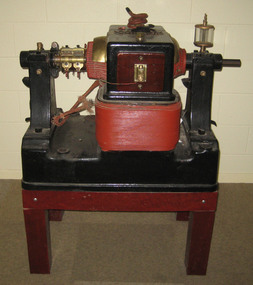
Equipment, Elwell-Powell, Elwell-Parker AC Generator
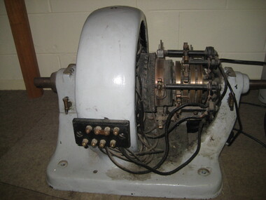
... Electric Construction Company, with Mr. Parker as manager of the lot. The whole of the works will be taken to Wolverhampton. Before I left, a tender for £50,000 was accepted for the construction of new works. generator ac generator elwell-parker ltd state electricity commission sec ballarat north power station james oddie wolverhampton AC Generator painted read and black on a stand. ...This AC generator operated for the State Electricity Commission in the Ballarat North Power Station prior to World War Two. James Oddie of Ballarat has an association with Thomas Parker of Elswell-Parker. In early 1887 Oddie arrived in England seeking information on electrical knowledge and its developments. At this time Henry Sutton was teaching Electricity and Magnetism at the Ballarat School of Mines. Oddie stayed in the United Kingdom for around three years and during that time became a close friend of Thomas Parker and his family. The two first met at the first official running of the Blackpool tram, and Oddie was invited to visit Parker at Wolverhampton. Over the years Thomas Parker kept newspaper cuttings (mainly Australian) relating to James Oddie and his work. The following article is a description of the Wolverhampton works by James Oddie, and was collected by Thomas Parker. After the dinner at Blackpool, Mr. Parker visited me, and cordially invited me to see his extensive works at Wolverhampton, an invitation I was not slow to avail myself of. This was the keynote of the best friendship I made in England. I went shortly afterwards and stayed several days, visiting the works daily, as Mr. Parker gave me the run of the whole works. There I ordered the installation of a 60 light dynamo, with a 28 cell storage battery and paraphernalia, now doing duty at the Observatory. I subsequently visited the works frequently, sometimes for a week at a time, and I regard it as the brightest spot in my English constellation. Mr. Parker started his works in 1880, with one man beside himself. He never had a single day’s instruction in electricity in his life; now he daily instructs between 300 and 400 employees, who worship him as a father. He is said to be now the most practical electrical engineer and mechanist in Europe. During one of my visits I took with me an artist, who is painting for me a portrait, 6 feet by 5 feet, of Mr. Parker, surrounded by dynamos, secondary batteries, measuring instruments etc. Electric tram cars are going to be a big thing in England. Parker’s Company Limited, is now, with three other companies, in the hands of the Electric Construction Company, with Mr. Parker as manager of the lot. The whole of the works will be taken to Wolverhampton. Before I left, a tender for £50,000 was accepted for the construction of new works.AC Generator painted read and black on a stand. This AC generator operated for the State Electricity Commission in the Ballarat North Power Station prior to World War Twogenerator, ac generator, elwell-parker ltd, state electricity commission, sec, ballarat north power station, james oddie, wolverhampton -
 Ballarat Tramway Museum
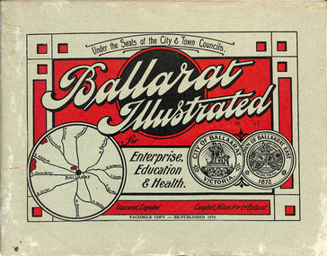
Book, "Ballarat Illustrated", 1972
... Page 68: Electric Supply Co. of Victoria's pages - top photo showing powerhouse in background, across the lake, can hardly see anything for the trees, except for the chimney. Bottom photos of the steam Turbo Generators...Page 68: Electric Supply Co. of Victoria's pages - top photo showing powerhouse in background, across the lake, can hardly see anything for the trees, except for the chimney. Bottom photos of the steam Turbo Generators ...Original c 1914 (see below), facsimile copy - re-published 1972. Original features photos of Ballarat City and Town, its buildings, parks and the various industries and organisations that were in Ballarat at the time of publication, including ESCo. Many photos features ESCo trams. Photos sepia toned. Has some red colour block printing on the front cover and rear, for Star Oil Engines. On inside back cover is a map with the places of interest and tram route map, marked in red. Pages are un-numbered. Original published by Ballarat East Town Council and Ballaarat City Council. On cover has number stamped in black in, "No. 87" (assume facsimile copy No.). Photos with publication show tram No. 21, built 1913 and ESCo photo page shows Mr. Pringle as Manager. Mr Pringle became manager in January 1911, As there is no photos of the "Avenue of Honour", or other mention of the first world war, assume original published about 1913 or 1914. Original shows Engravings and printing by "Campbell Wilson Prop Ltd, Ballarat". See Other Information as well for more listing details. High Resolution image added 31/8/2012 of i2 of ESCo page and i3 for Ballarat identies and sheet i4 extracted for Mr Pringle. PDF scan of full document added 21/5/2019 - see images btm633-1i.pdf and btm633-2i.pdf Notes on "Ballarat Illustrated" Reg. Item No. 733 From notes made by Neville Gower 12/1/1997 Cover: Inside front cover: Last paragraph, "Facilities for Travelling" - Electric trams serve all parts of Ballarat. Page 3: Street Scene, Municipal Town Hall, showing tram wiring Page 7: Street Scene, Lydiard St. North, intersection and tramway centre, with ESCo tram No. 21 in the bottom photo. Other photos features trams as well in Sturt St and Lydiard St. North. Page 9: Street Scene, Top photo of Sturt St. from Lydiard St. looking east, shows piles on right-hand side of road. Car parked by Post Office has a car registration number "9007". Bottom photo, an tram climbing hill, shows double trolley in the street, with early English type of pull offs. Page 13: Street Scenes and Historic Buildings: One of five photos, shows Victoria St. looking East, with tram track prominent in photo and how stone work was set up about the rails and overhead poles. Page 23: Street scene, Gardens North Entrance gates, shows details of gates near St. Aidans Drive. Note double trolley wire on poles, and style of insulators. No trams in photo, three ladies walking down the track. Page 37: Street Scene; Lydiard St views, top left hand photo, shows Railway station and railway gates with signal gantry and horse drawn vehicles. Tram tracks apparent. Bottom left hand photo shows Lydiard St. North, near Post Office, double track with centre poles - Single wire per track. Top right hand photo, showing Cemetery gates in background. Bottom right hand photo - from north end of Lydiard St. South, looking north, with an ESCo tram in background. Also has a parked car on left hand side. Page 45: Street Scenes - Bridge St; top photo at west end of Bridge St. with ESCo No. 11 with possibly double trolley wire in photo. Bottom photo at east end of Bridge St. with tram in background, shows junction. Double trolley heading out to Mt. Pleasant, single trolley for Victoria St. Page 45: Street Scenes - Bridge St; top photo at west end of Bridge St. with ESCo No. 11 with possibly double trolley wire in photo. Bottom photo at east end of Bridge St. with tram in background, shows junction. Double trolley heading out to Mt. Pleasant, single trolley for Victoria St. Page 61: Street Scenes and Historic Buildings - Public Institutions Ballarat - top left hand photo of the Hospital shows some tram track in foreground, with double trolley wire. Top right photo is of the Orphanage, the name of the tram terminus for many years. Page 68: Electric Supply Co. of Victoria's pages - top photo showing powerhouse in background, across the lake, can hardly see anything for the trees, except for the chimney. Bottom photos of the steam Turbo Generators and the switchboard. Gives Mr. P.J. Pringle as Chief Engineer and General Manager. He took over in Jan. 1911. Page 69: Ballarat East Views - features photo of Black Hill open cut, Ballarat East Railway Station, Ballarat Fire Station and "Victoria St. looking East", repeat of photo printed on page 12, but slightly darker. Image on system includes fire station and railway station, - Ballarat East. Page 78: Series of photos of various Ballarat VIP's of the era, fourth one in on top line features "P.J.Pringle, Electric Supply Co." Inside Back cover - map of Ballarat including tram lines and places of interest marked in red. Gives a detailed photographic presentation of Ballarat in 1914.80 page book with, in addition, light green card covers, titled "Ballarat Illustrated". Loose copy of page 9 and 10 held.trams, tramways, ballarat, local history, heritage buildings, esco -
 Hume City Civic Collection
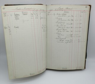
Cash Book, Cash Book Electric Lighting Shire of Bulla, 1909
... The Cash Book was used by the Shire of Bulla Electric Light Department to record by hand writing costs associated with supplying electricity, employee wages and users of electricity between October 1909 and November 1926. The first two generators...Hume City Civic Collection 44 Macedon Street Sunbury melbourne The Cash Book was used by the Shire of Bulla Electric Light Department to record by hand writing costs associated with supplying electricity, employee wages and users of electricity between October 1909 and November 1926. The first two generators ...The Cash Book was used by the Shire of Bulla Electric Light Department to record by hand writing costs associated with supplying electricity, employee wages and users of electricity between October 1909 and November 1926. The first two generators supplied the township of Sunbury and together with the erection of a Power House were officially opened in 1910. The State Electricity Commission took over the supply of electricity in Sunbury in 1926.Large green cloth covered hard cover with tan corners and spine. Tan and purple mottled pattern inside front and back cover."Arnall & Jackson/Engravers..."1900s, shire of bulla, sunbury, george evans collection -
 Wodonga & District Historical Society Inc
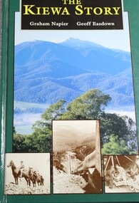
Book - The Kiewa Story, Graham Napier et al, 1993
... Wodonga & District Historical Society Inc Hut 97, Bonegilla Migrant Experience, 132 Bonegilla Road Bonegilla the-murray kiewa valley hydro scheme victorian alpine region electricity generators electric power production -- victoria This publication details the development of the Kiewa Valley region with respect to population as well as the strong physical changes brought to the relatively pristine alpine region. ...This publication details the development of the Kiewa Valley region with respect to population as well as the strong physical changes brought to the relatively pristine alpine region. The impact the growing regional population places on the environment is clearly documented in print and black and white photographs.non-fictionThis publication details the development of the Kiewa Valley region with respect to population as well as the strong physical changes brought to the relatively pristine alpine region. The impact the growing regional population places on the environment is clearly documented in print and black and white photographs.kiewa valley, hydro scheme, victorian alpine region, electricity generators, electric power production -- victoria -
 El Dorado Museum Association Inc.
Photograph (item) - Digital Image
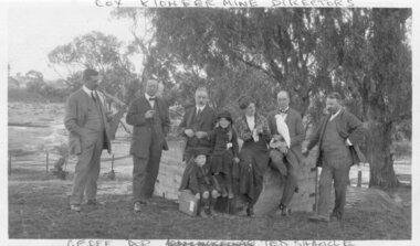
... Electric Gold & Tin Mine Company was formed in 1899. The company's first power station, located at the eastern end of the valley began operating with its 340 Kilowatt steam-powered generator. ...Electric Gold & Tin Mine Company was formed in 1899. The company's first power station, located at the eastern end of the valley began operating with its 340 Kilowatt steam-powered generator. ...Image of Cocks Pioneer Gold & Tin Mines NL directors with Mrs Molly Moline and children, Dorothy and Geoff. Taken at Sherwood - the mine manager's residence. (1914) Cocks Pioneer Electric Gold & Tin Mine Company was formed in 1899. The company's first power station, located at the eastern end of the valley began operating with its 340 Kilowatt steam-powered generator. By 1909, from 2,500,000 cubic yards worked, reported recovery was 17,284 ounces of gold and 224 tons of tin ore. By 1909, Cocks Pioneer’s power plant had become inadequate and uneconomical. The barge was floated downstream about a mile, but lost time caused the operations to cease. Following testing, a new mine was established by diverting Reid's Creek at a cost of £25 000. Settling dams were built, one of which held 1,935,900 cubic feet. Sold earth banks, built against a wall of stringy bark saplings constructed and laced with vertical props, were built. In 1914, the company was reformed as Cock’s Pioneer Gold and Tin Mines NL, another power station was constructed at the western end of the township, near the junction of Clear and Reid's Creeks. From 6,800,000 cubic yards of material processed, the returns were 64,397 ounces of gold and 855 ton of tin. Cocks Pioneer mine then moved the barge downs stream and continued sluicing. In 1929 Cocks Pioneer Electric Gold and Tin Mining Company ceased operations due to a drop in values. Cock’s Pioneer Gold and Tin Mines NL carried on large-scale hydraulic sluicing operations until 1941. "COX PIONEER MINE DIRECTORS" top "GEOFF DOR (unclear) TED SHACKLE" bottommine, gold, tin, gold mining, tin mining, cockatoos, sluicing, men, women, children, cocks pioneer, el dorado, eldorado -
 El Dorado Museum Association Inc.
Photograph (item) - Digital Image
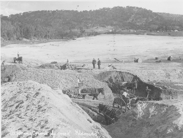
... Electric Gold & Tin Mine Company was formed in 1899. The company's first power station, located at the eastern end of the valley began operating with its 340 Kilowatt steam-powered generator. ...Electric Gold & Tin Mine Company was formed in 1899. The company's first power station, located at the eastern end of the valley began operating with its 340 Kilowatt steam-powered generator. ...Altering course of Reedy Creek, El Dorado. Cocks Pioneer Electric Gold & Tin Mine Company was formed in 1899. The company's first power station, located at the eastern end of the valley began operating with its 340 Kilowatt steam-powered generator. By 1909, from 2,500,000 cubic yards worked, reported recovery was 17,284 ounces of gold and 224 tons of tin ore. By 1909, Cocks Pioneer’s power plant had become inadequate and uneconomical. The barge was floated downstream about a mile, but lost time caused the operations to cease. Following testing, a new mine was established by diverting Reid's Creek at a cost of £25 000. Settling dams were built, one of which held 1,935,900 cubic feet. Sold earth banks, built against a wall of stringy bark saplings constructed and laced with vertical props, were built. In 1914, the company was reformed as Cock’s Pioneer Gold and Tin Mines NL, another power station was constructed at the western end of the township, near the junction of Clear and Reid's Creeks. From 6,800,000 cubic yards of material processed, the returns were 64,397 ounces of gold and 855 ton of tin. Cocks Pioneer mine then moved the barge downs stream and continued sluicing. In 1929 Cocks Pioneer Electric Gold and Tin Mining Company ceased operations due to a drop in values. Cock’s Pioneer Gold and Tin Mines NL carried on large-scale hydraulic sluicing operations until 1941. Handwritten across the front: 'Altering course of creek. Eldorado'mining, gold, tin, sluicing, reedy creek, cocks pioneer, el dorado, eldorado, men, horses -
 El Dorado Museum Association Inc.
Photograph (item) - Digital Image
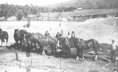
... Electric Gold & Tin Mine Company was formed in 1899. The company's first power station, located at the eastern end of the valley began operating with its 340 Kilowatt steam-powered generator. ...Electric Gold & Tin Mine Company was formed in 1899. The company's first power station, located at the eastern end of the valley began operating with its 340 Kilowatt steam-powered generator. ...Horse team , Cocks Pioneer Cocks Pioneer Electric Gold & Tin Mine Company was formed in 1899. The company's first power station, located at the eastern end of the valley began operating with its 340 Kilowatt steam-powered generator. By 1909, from 2,500,000 cubic yards worked, reported recovery was 17 284 ounces of gold and 224 tons of tin ore. By 1909, Cocks Pioneer’s power plant had become inadequate and uneconomical. The barge was floated downstream about a mile, but lost time caused the operations to cease. Following testing, a new mine was established by diverting Reid's Creek at a cost of £25,000. Settling dams were built, one of which held 1,935,900 cubic feet. Sold earth banks, built against a wall of stringy bark saplings constructed and laced with vertical props, were built. In 1914, the company was reformed as Cock’s Pioneer Gold and Tin Mines NL, another power station was constructed at the western end of the township, near the junction of Clear and Reid's Creeks. From 6,800,000 cubic yards of material processed, the returns were 64,397 ounces of gold and 855 ton of tin. Cocks Pioneer mine then moved the barge downs stream and continued sluicing. In 1929 Cocks Pioneer Electric Gold and Tin Mining Company ceased operations due to a drop in values. Cock’s Pioneer Gold and Tin Mines NL carried on large-scale hydraulic sluicing operations until 1941. mining, gold, tin, sluicing, men, cocks pioneer, el dorado, eldorado, horses, gold mining, tin mining -
 El Dorado Museum Association Inc.
Photograph (item) - Digital Image
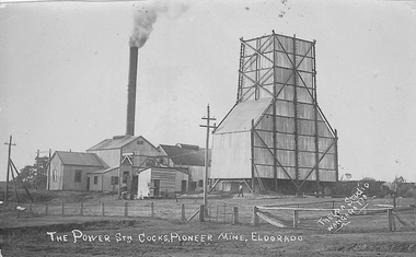
... Electric Gold & Tin Mine Company was formed in 1899. The company's first power station, located at the eastern end of the valley began operating with its 340 Kilowatt steam-powered generator. ...Electric Gold & Tin Mine Company was formed in 1899. The company's first power station, located at the eastern end of the valley began operating with its 340 Kilowatt steam-powered generator. ...Cocks Pioneer Mine El Dorado, Power Station No. 2 was established in 1914 and located near junction of Reid's and Clear Creeks, Byawatha. Cocks Pioneer Electric Gold & Tin Mine Company was formed in 1899. The company's first power station, located at the eastern end of the valley began operating with its 340 Kilowatt steam-powered generator. By 1909, from 2,500,000 cubic yards worked, reported recovery was 17,284 ounces of gold and 224 tons of tin ore. By 1909, Cocks Pioneer’s power plant had become inadequate and uneconomical. The barge was floated downstream about a mile, but lost time caused the operations to cease. Following testing, a new mine was established by diverting Reid's Creek at a cost of £25,000. Settling dams were built, one of which held 1,935,900 cubic feet. Sold earth banks, built against a wall of stringy bark saplings constructed and laced with vertical props, were built. In 1914, the company was reformed as Cock’s Pioneer Gold and Tin Mines NL, another power station was constructed at the western end of the township, near the junction of Clear and Reid's Creeks. From 6,800,000 cubic yards of material processed, the returns were 64,397 ounces of gold and 855 ton of tin. Cocks Pioneer mine then moved the barge downs stream and continued sluicing. In 1929 Cocks Pioneer Electric Gold and Tin Mining Company ceased operations due to a drop in values. Cock’s Pioneer Gold and Tin Mines NL carried on large-scale hydraulic sluicing operations until 1941. Handwritten on front: 'THE POWER STN COCKS, PIONEER MINE, ELDORADO' / 'THELMA STUDIO / [underlined] WANGARATTA'mining, gold, tin, cocks pioneer, power, sluicing, el dorado, eldorado, byawatha, thelma studios, wangaratta, gold mining, tin mining, reid's creek, clear creek -
 El Dorado Museum Association Inc.
Photograph (item) - Digital Image
... Electric Gold & Tin Mine Company was formed in 1899. The company's first power station, located at the eastern end of the valley began operating with its 340 Kilowatt steam-powered generator. ...Electric Gold & Tin Mine Company was formed in 1899. The company's first power station, located at the eastern end of the valley began operating with its 340 Kilowatt steam-powered generator. ...Cocks Pioneer Creek Diversion. Cocks Pioneer Electric Gold & Tin Mine Company was formed in 1899. The company's first power station, located at the eastern end of the valley began operating with its 340 Kilowatt steam-powered generator. By 1909, from 2,500,000 cubic yards worked, reported recovery was 17,284 ounces of gold and 224 tons of tin ore. By 1909, Cocks Pioneer’s power plant had become inadequate and uneconomical. The barge was floated downstream about a mile, but lost time caused the operations to cease. Following testing, a new mine was established by diverting Reid's Creek at a cost of £25,000. Settling dams were built, one of which held 1,935,900 cubic feet. Sold earth banks, built against a wall of stringy bark saplings constructed and laced with vertical props, were built. In 1914, the company was reformed as Cock’s Pioneer Gold and Tin Mines NL, another power station was constructed at the western end of the township, near the junction of Clear and Reid's Creeks. From 6,800,000 cubic yards of material processed, the returns were 64,397 ounces of gold and 855 ton of tin. Cocks Pioneer mine then moved the barge downs stream and continued sluicing. In 1929 Cocks Pioneer Electric Gold and Tin Mining Company ceased operations due to a drop in values. Cock’s Pioneer Gold and Tin Mines NL carried on large-scale hydraulic sluicing operations until 1941. mining, gold, tin, cocks pioneer, creek, gold mining, tin mining, el dorado, eldorado