Showing 17 items matching "electric power control"
-
 Kiewa Valley Historical Society
Electrical Equipment - Relays
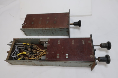
... ...electric power control...power stations. Manually operated by remote control for an external circuit breaker. The relays were from a Kiewa Hydro Power Station control panel. power circuits electrical equipment electric power control power relays power station circuit breaker One has a plaque attached. ...Protective relays are one of the critical components of the elctrical power grid that serve to detect defective equipment or other dangerous or intolerable conditions and can either initiate or permit switching or simply provide an alarm to provide an alarm to provide a safer, more reliable delivery system. Used in power stations. The function of relay is to quickly remove from service any equipment that might suffer damage or otherwise affect the operation of the system. Relays protect the electrical system in 2 ways: Prevent failure or damage to electrical systems. Mitigate the effects of failure when it occurs. Switches that control other switches. Relays are used where it is necessary to control a circuit by an independent low-power signal, or where several circuits must be controlled by one signal.Used by the State Electricity Commission of Victoria for the Kiewa Hydro Electric Scheme in the power stations. Manually operated by remote control for an external circuit breaker. The relays were from a Kiewa Hydro Power Station control panel.Collection of black metal rectangular boxes (heavy) containing electrical wires forming a circuit. The longer, narrower rectangles have a bakelite knob at one end. Some of the boxes have one side of clear perspex and another has all sides of clear perspex. One is labelled "group relay". Another has windows with labels eg. 'turbine overspeed' 'emergency trip' and one has 3 steel knobs. - with 'stop', 'start'. One box is larger than the rest and has clear perspex side showing 'overcurrent relay' and workings.One has a plaque attached. Manufacture: "The English Co. Ltd. Londonpower circuits, electrical equipment, electric power control, power relays, power station, circuit breaker -
 Kiewa Valley Historical Society
Booklet - Mt Beauty and the Kiewa Scheme x2
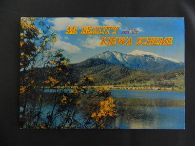
... Also Tawonga Camping ground, Bogong Village, Mt Beauty Chalet, the Control panel at Kiewa Power Station, Clover Dam at No. 3 Power Station, the road to Falls Creek and a view of Mt Beauty township. The photos indicate what Mt Beauty and the Kiewa Valley and High Plains looked like c1950's during the construction of the Kiewa Hydro Electric Scheme. ...This booklet was produced to advertise Mt Beauty, the Kiewa Scheme & surrounding areas to visitors / tourists. The photos cover Falls Creek with snow, lifts and skiers - one with Spion Kopje Lodge. Also Tawonga Camping ground, Bogong Village, Mt Beauty Chalet, the Control panel at Kiewa Power Station, Clover Dam at No. 3 Power Station, the road to Falls Creek and a view of Mt Beauty township. The photos indicate what Mt Beauty and the Kiewa Valley and High Plains looked like c1950's during the construction of the Kiewa Hydro Electric Scheme. The area was recognised and encouraged as a tourist attraction especially Falls Creek enabling comparison with later photos and ideas. A fold down booklet postcard size of 12 colored photos - back to back of Mt Beauty, the Kiewa Scheme & surrounds. They fold in to form a front photo with title and a back card for stamp & address of addressee. On the back of the front photo are a few paragraphs describing the beauty, history and 'things to do' in the area for the visitor / tourist. mt beauty; kiewa scheme; tawonga; bogong; clover dam; kiewa valley; bogong high plains -
 Kiewa Valley Historical Society
Photo - Bogong Village Township, October 8, 1946
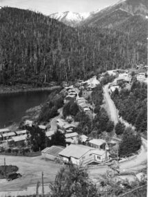
... control has not allowed for any extensive redevelopment in tourist accommodation and basically restricted it to the accommodation initially built for the construction workers. Activities such a bike riding, snow skiing, restricted horse riding and bush walking on the Alpine plains and mountains are now a viable part of the Kiewa Valley Tourist Industry. The lake is one of the many water storage reservoirs used to supply the power stations their main power to run the huge turbines generating the final product, electricity Bogong Village; Lake Guy; Kiewa Hydro Electric ...In 1940 Field Headquarters for the Kiewa Scheme were established at Bogong with office, workshop facilities and accommodation for workmen, staff and some families constructed. (There had been a 'tent camp' on this site in 1939 but was destroyed by bushfires) Construction of accommodation continued until 1947. A total of 40 houses plus a hostel for single staff, post office, police station, medical centre and primary school all with water and sewerage and electricity supply. The staff hostel was known as Kiewa House and is now occupied by the Education Department. Lake Guy was named after Mr. L.T. Guy who was the Resident Engineer in charge of construction work and associated activities on the Kiewa area. He held this position from 1939 to November 1946 when he was transferred to Head Office. The Bogong Township was developed firstly as an accommodation centre (base camp) for construction workers employed under the Kiewa Hydroelectric Scheme. Due to the influx of European workers into the Township the beautification of the immediate surrounds (gardens etc.) had a distinct European flavour. This environment has been very beneficial for tourism in later years. At the completion of the scheme, in the 1960's, the village was opened to public/tourism use. Strict environmental control has not allowed for any extensive redevelopment in tourist accommodation and basically restricted it to the accommodation initially built for the construction workers. Activities such a bike riding, snow skiing, restricted horse riding and bush walking on the Alpine plains and mountains are now a viable part of the Kiewa Valley Tourist Industry. The lake is one of the many water storage reservoirs used to supply the power stations their main power to run the huge turbines generating the final product, electricityBlack and white photograph of Bogong Village which appeared in the Herald Sun newspaper on October 8, 1946. Page 13Handwritten on the back - Town of Bogong on a rugged mountain slope above Lake Guy. State Electricity Committee workers on the Kiewa Hydro Electric scheme live here in all electric homes. Stamped on the back - Copyright Not for reproduction Herald Sun Feature Service Melbourne Australiabogong village; lake guy; kiewa hydro electric scheme -
 Kiewa Valley Historical Society
Photograph – Black and white photograph of an unidentified piece of equipment (possibly projection equipment) presumably used by SECV Hydro
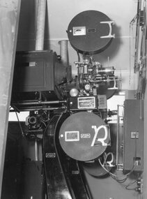
... control of power generation in 1921, forming the State Electricity Commission (SEC). Construction approval on a grand scheme to build five power stations with a combined capacity of 289 megawatts was received in 1938, and the Clover Power Station was completed by 1945. The original scheme was dramatically pruned after World War II and only two more power stations were built. The Junction Dam and Clover Dam Power Station, stages of the Kiewa Hydro-Electric...control of power generation in 1921, forming the State Electricity Commission (SEC). Construction approval on a grand scheme to build five power stations with a combined capacity of 289 megawatts was received in 1938, and the Clover Power Station was completed by 1945. The original scheme was dramatically pruned after World War II and only two more power stations were built. The Junction Dam and Clover Dam Power Station, stages of the Kiewa Hydro-Electric ...The Victorian Government took control of power generation in 1921, forming the State Electricity Commission (SEC). Construction approval on a grand scheme to build five power stations with a combined capacity of 289 megawatts was received in 1938, and the Clover Power Station was completed by 1945. The original scheme was dramatically pruned after World War II and only two more power stations were built. The Junction Dam and Clover Dam Power Station, stages of the Kiewa Hydro-Electric Scheme, were needed to meet the increased power demands of the wartime industry in Victoria. Clover added 26 megawatts to the grid. Junction Dam was completed and ready to hold water by September 1943, but was emptied in December 1943 and not filled again until May 1944. Construction of Clover Power Station commenced in July 1941 and both turbines were in service by May 1945.Clover Power Station and Junction Dam were part of the Kiewa Hydro Electric Scheme constructed by the State Electricity Commission of Victoria.Black and white photograph of an unidentified piece of equipment (possibly projection equipment) presumed to be used in one of the power stations ie: Clover Power Station or Junction Dam as part of the Kiewa Hydro Electric Schemeprojection equipment; -
 Kiewa Valley Historical Society
Photograph – Set of 3 black and white photographs of Bogong Village circa late 1930's - 1940's during early construction of Lake Guy ( in the foreground), Late 1930's - 1940's
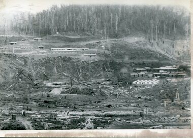
... control has not allowed for any extensive redevelopment in tourist accommodation and basically restricted it to the accommodation initially built for the construction workers. Activities such a bike riding, snow skiing, restricted horse riding and bush walking on the Alpine plains and mountains are now a viable part of the Kiewa Valley Tourist Industry. The lake is one of the many water storage reservoirs used to supply the power stations their main power to run the huge turbines generating the final product, electricity bogong village; junction dam; lake guy; kiewa hydro electric ...In 1940 Field Headquarters for the Kiewa Scheme were established at Bogong with office, workshop facilities and accommodation for workmen, staff and some families constructed. (There had been a 'tent camp' on this site in 1939 but was destroyed by bush fires) Construction of accommodation continued until 1947. A total of 40 houses plus a hostel for single staff, post office, police station, medical centre and primary school all with water and sewerage and electricity supply. The staff hostel was known as Kiewa House and is now occupied by the Education Department. Lake Guy was named after Mr. L.T. Guy who was the Resident Engineer in charge of construction work and associated activities on the Kiewa area. He held this position from 1939 to November 1946 when he was transferred to Head Office. The Bogong Township was developed firstly as an accommodation centre (base camp) for construction workers employed under the Kiewa Hydroelectric Scheme. Due to the influx of European workers into the Township the beautification of the immediate surrounds (gardens etc.) had a distinct European flavour. This environment has been very beneficial for tourism in later years. At the completion of the scheme, in the 1960's, the village was opened to public/tourism use. Strict environmental control has not allowed for any extensive redevelopment in tourist accommodation and basically restricted it to the accommodation initially built for the construction workers. Activities such a bike riding, snow skiing, restricted horse riding and bush walking on the Alpine plains and mountains are now a viable part of the Kiewa Valley Tourist Industry. The lake is one of the many water storage reservoirs used to supply the power stations their main power to run the huge turbines generating the final product, electricity3 black and white photographs of the Bogong camp area showing the clearing of trees for the construction of the Junction Dam and Lake Guy. Some administration buildings have been constructed, but part of the tent camp can be seen to the right of the photograph in front of the buildings. bogong village; junction dam; lake guy; kiewa hydro electric scheme; secv -
 Kiewa Valley Historical Society
Electric Current Shunt
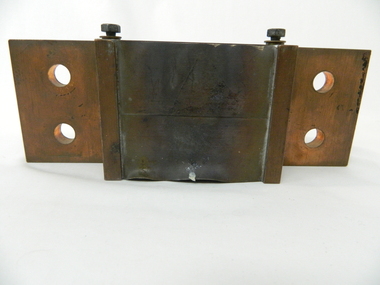
... control metering system. It reduces the large current to a small voltage. Historical: This equipment represents a major construction and ongoing operational industry dealing with the supply of hydro electricity to Victoria. kiewa hydro electric scheme. secv. hydro generator. victorian electricity grid power station. electricity. resistor Screwed in metal plaque: Deriv. 1662691 / OHM 0.0000833 / AMP 1200 on the side of the cube above a shelf and on the opposite shelf: ALTO ----> (also a metal plaque screwed on). ...This shunt is a type of resistor built of copper and designed to carry a current. It was part of the Hydro generator control metering system. It reduces the large current to a small voltage.Historical: This equipment represents a major construction and ongoing operational industry dealing with the supply of hydro electricity to Victoria.Made of copper the shunt has a middle cube with 12 sheets of copper, 5mm apart formed like shelves. On either side of the cube are two shelves coming out from the middle. Both have 2 hollow circles 17.5mm in diameter 25 mm apart in the middle. At the Join of the 'shelves' and cube is a screw on each side.Screwed in metal plaque: Deriv. 1662691 / OHM 0.0000833 / AMP 1200 on the side of the cube above a shelf and on the opposite shelf: ALTO ----> (also a metal plaque screwed on). kiewa hydro electric scheme. secv. hydro generator. victorian electricity grid, power station. electricity., resistor -
 Kiewa Valley Historical Society
Postcard - Mt Beauty and the Kiewa Hydro Electric Scheme
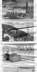
... Power Station, Kiewa 9. Control Room, No. 4 Power Station, Kiewa 10. Winter Scene at Rocky Valley on the Bogong High Plains 11. Water Channel, Mt Bogong in Background 12. Mt Beauty Township, Kiewa Valley Postcard - Mt Beauty and the Kiewa Hydro Electric ...SECV constructed the Kiewa Hydro Electric Scheme including the township of Mt Beauty. The area became a popular tourist destination.Tourism in the Kiewa Valley especially at Mt Beauty and the Bogong High Plains along with the Kiewa Hydro Electric Scheme became very popular and an important industry.Fold out b & w postcard with 12 photos back to back. All with a title. Kate 1950s 1. High Voltage Transmission Line, showing Mount Beauty Township 2. Clover Dam Reservoir, Kiewa 3. No. 3 Power Station, Kiewa 4. Generators, No. 3 Power Station 5. Turbines, No. 4 Power Station, Kiewa 6. junction Dam, Bogong 7. Mt Beauty Village Shopping Centre 8. Switchyard, No. 4 Power Station, Kiewa 9. Control Room, No. 4 Power Station, Kiewa 10. Winter Scene at Rocky Valley on the Bogong High Plains 11. Water Channel, Mt Bogong in Background 12. Mt Beauty Township, Kiewa Valleytransmission line, power station, generators, mt beauty, turbines, junction dam, switchyard, rocky valley, control room -
 Flagstaff Hill Maritime Museum and Village
Tool - Tilting Saw Bench, W F & John Barnes, 1874 to 1880
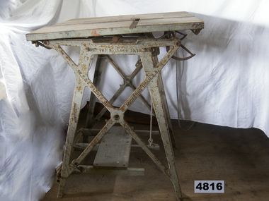
... powered machinery and specialised in making scroll saws. By 1937 the company focus had completely shifted to automotive assembly machinery, and custom-built machinery, machine tools, electrical, hydraulic, and mechanical controls and systems, including nuclear hardware. their production of foot-powered machinery had ceased. In the intervening years, they have got out of manufacturing completely. After a series of ownership changes, their equipment parts and stock were purchased in 1998 by LeBlond Ltd. of Amelia, Ohio. An item that although incomplete gives a snapshot into the manufacture and use of early woodworking machinery before the introduction of electricity or electric ...he subject item is a pedal-powered rip saw with a tilting table made in the USA by W.F. & John Barnes Co. of Rockford, Illinois, between 1874 and 1890. The saw's blade moves rapidly in a circular motion and is driven by a pedal that spins a heavy flywheel with a leather belt attached to a gear drive that in turn drives the circular saw blade. The operator holds a wood workpiece on the table and moves it forward so the blade cuts it to the desired width and length. Company History: WF & John Barnes Co. was established in 1869, by making a formal partnership between William F. Barnes and John Barnes in 1872, and then incorporating in 1884. This company was an early manufacturer of pedal-powered equipment. By 1881 they were also making powered machinery such as lathes and pedestal drills. Many companies were making lightweight foot-powered equipment, but Barnes and the Seneca Falls Co. were the only ones to also make professional-grade workshop machines. From the beginning of their existence, they focused on pedal-powered machinery and specialised in making scroll saws. By 1937 the company focus had completely shifted to automotive assembly machinery, and custom-built machinery, machine tools, electrical, hydraulic, and mechanical controls and systems, including nuclear hardware. their production of foot-powered machinery had ceased. In the intervening years, they have got out of manufacturing completely. After a series of ownership changes, their equipment parts and stock were purchased in 1998 by LeBlond Ltd. of Amelia, Ohio. An item that although incomplete gives a snapshot into the manufacture and use of early woodworking machinery before the introduction of electricity or electric motors to power machines.A treadle powered tilting table saw bench"WF & J Barnes, Rockford Ill USA"flagstaff hill, flagstaff hill maritime museum and village, warrnambool, maritime museum, maritime village, great ocean road, shipwreck coast, tilting saw bench, saw bench, 19th century saw bench, treadle saw bench, woodworking building equipment, carpentry equipment, carpentry, w. f. and j. barnes, usa -
 Federation University Historical Collection
Object, Synchronome Co. Ltd, Synchronome Frequency Checking Master Clock No. 2191, c1930
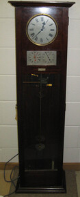
... control panel in the Power Station. A maximum deviation between the two dials was set in the operating instructions (eg 5 seconds) and the operator would correct this when necessary by remote manual alteration of the turbine governor set point. The clock was used to drive and regulate a system of "slave" clocks which were used to display the time in various locations around the power station. A slave clock is a simple clock which is driven by a small electric...control panel in the Power Station. A maximum deviation between the two dials was set in the operating instructions (eg 5 seconds) and the operator would correct this when necessary by remote manual alteration of the turbine governor set point. The clock was used to drive and regulate a system of "slave" clocks which were used to display the time in various locations around the power station. A slave clock is a simple clock which is driven by a small electric ...Information from Norman F. Dalton: Ballarat had a reticulated DC supply in the early part of last century and in 1905 had sufficient generating capacity to enable the trams to be changed from horse drawn to DC electricity. The use of electricity increased with the main power station located on Wendouree Parade, near Webster Street, under the ownership of The Electric Supply Company of Victoria. AC generating plant was installed in 1925 and conversion to AC proceeded. In 1934 the company was taken over by the State Electricity Commission Victoria (SECV) and more AC generation was installed and the changeover of customers was accelerated. This is around the time that the Synchronome Frequency Checking Mast Clock was installed at the Wendouree Parade Power Station. The SECV Annual Report of 1921 states: ::Section 11 of the act directed the COmmission to enquire into the question of securing the adoption of such standards of plant and equipment of a system, frequency and pressure for the generation and distribution of electricity as will admit of the efficient interconnection of undertakings throughout the State. In 1934 when the SECV took over the Ballarat operations the question of linking with the State grid had been a planned operation for some years but due to financial considerations had hindered it and in fact would continue to do so for a further 10 years. So while the need for close frequency control for interconnection was hardly an issue, the need to keep electric clocks correct was important, particularly as this item was a frequent sales point to cover the inconvenience and sometimes expense of converting from DC to AC. The clock is a very accurate pendulum clock with provision for varying effective length during operation for precise time regulation. There are two normal time dials and one is controlled by the pendulum and the other is operated by the system frequency. When the clock was in use it was installed by the MEter and Tests Laboratory and the time was checked daily by radio time signals. The two dials were repeated in the operators control panel in the Power Station. A maximum deviation between the two dials was set in the operating instructions (eg 5 seconds) and the operator would correct this when necessary by remote manual alteration of the turbine governor set point. The clock was used to drive and regulate a system of "slave" clocks which were used to display the time in various locations around the power station. A slave clock is a simple clock which is driven by a small electric motor, its accuracy is regulated by the master clock every 30 seconds to ensure that it and all the other slave clocks in the station are on exactly the right time; slave clocks were placed in various locations, from common rooms to workshops. A master clock could potentially run thousands of slave clocks at one plant. The clock also contains a rectifier. A rectifier is a device that is used to convert AC power to more stable DC current.Two clocks in a timber case. Both are electric, one is powered by the main pendulum mechanism, the other is a self contained electric clock. The main mechanism is of the gravity arm and roller type, which sends an impulse to the slave clocks every 30 seconds. The This Synchronome Frequency Checking Master Clock was used at the Ballarat Power Station. Below the main section of the case is a smaller cabinet containing a rectifier to provide consistent DC power for the clock. The rectifier was made by the Victorian company Hilco, which was located in Burwood. There is a high chance this is not the original rectifier from this clock as there appears to be brackets to hold a larger device in the space the rectifier occupies.Front below main clock face on front of case: "Patented Sychronome Brisbane" Lower left-hand clock face: "Frequency time" Lower right-hand clock face: "Standard Seconds" Synchronous electric clock mechanism on door (Frequency time clock): >200/250 V. 50~ >"Synchronomains" Made in England >Direction indicator for clock starting switch >"To start move lever in direction of arrow and release" >"Patent applied for" Mechanism for "standard seconds" clock: >"English Made" >"Patented" >Serial number "321" >0 above right-hand pillar on front-plate Mechanism for "standard seconds" clock: >"English Made" >"Patented" >Serial number "321" >0 above right-hand pillar on front-plate Mechanism for main clock face: >"English Made" >"Patented" >Serial number "8751" >0 above right-hand pillar on front-plate Inside case, back panel, top enamel plate: >Seconds Battery + Pos. > Battery Common or - Neg. >1/2 min dials Inside case, back panel, bottom enamel plate: external seconds dial Inside case, right hand side, electrical knobs: two switches, both "A.C. mains" Pendulum rod, below suspension spring: Serial number (?) 0000005 Rectifier in bottom cabinet: >"Hilco Rectifier" >"A.C. Volts 230/240" >"Model 1060/S" >"A.C. Amperes" >"Serial No. 1060/S >"Phases 1" >"D.C. Volts 6" >"C.P.S. 50" >"D.C. Amperes 1" >"Made in Australia by Hilco Transformers McIntyre St., Burwood, Victoria." Bakelite electrical plug: makers mark Lower cabinet, RH side panel, pressed tin plate: "AC" (upside down) Brass speed adjustment, outer right RH side: "S" and "F" Ivory and wood pendulum beat ruler: >Ruler, with 0 in centre and numbers 1-5 in ascending order from centre on left and right. > "Synchronome Patent." Steel plate, back panel, inside case, right hand side: >N R A" (descending) >"2191" serial number/part number Face of main clock: "Synchronome Electric" synchronome frequency checking master clock, electricity, state electricity commission, wendouree parade power station, secv, clock, time, pendulum, electric supply company of victoria, norman f. dalton, ballarat power station, rectifier, slave clock -
 Geoffrey Kaye Museum of Anaesthetic History
Photograph
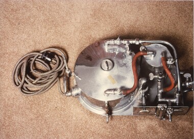
... The vaporiser is metal and circular, and has metal valves and controls and two orange tubes. The machine has an electric cord and power plug which is coiled on the floor....electric lamp heater. Anaesthetic equipment Lidwill anaesthetic machine Mark Lidwill Ether vaporiser Anaesthetic and Portable Machine Company of Sydney Vaporiser Colour photograph of a modified Lidwill anaesthetic machine sitting on carpet, taken from above. The vaporiser is metal and circular, and has metal valves and controls and two orange tubes. The machine has an electric cord and power ...The Lidwill machine was designed by Mark Lidwill in 1913, for the purpose of mechanical or insufflation anaesthesia. It was manufactured by Elliott Bros. of Sydney. Shortly afterwards, the Anaesthetic and Portable Machine Company of Sydney devised a machine that was functionally the same but also contained an electric lamp heater.Colour photograph of a modified Lidwill anaesthetic machine sitting on carpet, taken from above. The vaporiser is metal and circular, and has metal valves and controls and two orange tubes. The machine has an electric cord and power plug which is coiled on the floor.anaesthetic equipment, lidwill anaesthetic machine, mark lidwill, ether vaporiser, anaesthetic and portable machine company of sydney, vaporiser -
 Ballarat Tramway Museum
Document - Folder with papers, Garry Wood and Paul Mong, "Ballarat Tramway Museum / Electrical Diagrams for Sub Station / 12-11-2005", Nov. 2005
... Ballarat Tramway Museum South Gardens Reserve Wendouree Parade Ballarat Ballarat goldfields Trams tramways Substation BTM Power Supply Blue Victory plastic folder with clear front cover, containing 15 plastic sheet protectors and printed or photocopied sheets detailing the equipment in the rebuilt BTM Sub-station. Titled "Ballarat Tramway Museum / Electrical Diagrams for Sub Station / 12-11-2005", details control circuit, Traction Encloser, Cabinet C1, Cabinet C2, Cabinet C/C3, photographs, parts list, Micro electrics, Traction Contactors, Type LTHS, K&J Magnetics, NHP under or over current single phase relays, and Carlo Cavazzi Monitoring Relays. ...Blue Victory plastic folder with clear front cover, containing 15 plastic sheet protectors and printed or photocopied sheets detailing the equipment in the rebuilt BTM Sub-station. Titled "Ballarat Tramway Museum / Electrical Diagrams for Sub Station / 12-11-2005", details control circuit, Traction Encloser, Cabinet C1, Cabinet C2, Cabinet C/C3, photographs, parts list, Micro electrics, Traction Contactors, Type LTHS, K&J Magnetics, NHP under or over current single phase relays, and Carlo Cavazzi Monitoring Relays.trams, tramways, substation, btm, power supply -
 Whitehorse Historical Society Inc.
Audio - Record Player, C. 1960
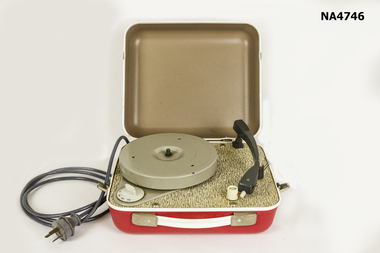
... Has speed control marked N_16_33_45_78. 240 volt electric power lead coming through hole in base plate. ...Has speed control marked N_16_33_45_78. 240 volt electric power lead coming through hole in base plate. ...Bought by donor in 1976 to play 78 rpm records. Second hand purchase probably first played C. 1960. 16 rpm records first produced in 1955.Light brown and red case with white band around middle. Has hinged lid and white carry handle on front. Lid hinges to rear with two clips to hold shut on sides. Inside has 18cm turntable, volume control knob and stylus arm with LP and 78 stylus on end. Has speed control marked N_16_33_45_78. 240 volt electric power lead coming through hole in base plate. Has small clip to hold down stylus arm when in transit. In working order.No markingsaudio-visual technology, audio appliances -
 Melbourne Tram Museum
Ephemera - Calendar, Yarra Trams, "Yarra trams calendar 2007", 2006
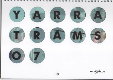
... Features trams 909 (100 years of electric trams), 5016, 210, 881, VR 53 and 40 at St Kilda, model trams at Kew Depot 75th, 2071, 3012, Power control room in 1938, City Circle car at Tram It, 2006. ...Melbourne Tram Museum 8 Wallen Road Hawthorn melbourne Trams tramways Yarra Trams Calendar Employees Drivers 100 years of electric trams St Kilda Railway Station Victorian Railways Kew Depot Carlton Control tram 909 tram 5016 tram 210 tram 881 tram 53 tram 40 tram 2071 tram 3012 .1 - Wall Calendar - 2007 - wire spiral bound along top edge, semi gloss paper, with cover and each month featuring various Yarra Trams employees and with tram and other photographs by employees. Names listed in key Associations. Has a hole in the top edge. Features trams 909 (100 years of electric trams), 5016, 210, 881, VR 53 and 40 at St Kilda, model trams at Kew Depot 75th, 2071, 3012, Power ....1 - Wall Calendar - 2007 - wire spiral bound along top edge, semi gloss paper, with cover and each month featuring various Yarra Trams employees and with tram and other photographs by employees. Names listed in key Associations. Has a hole in the top edge. Features trams 909 (100 years of electric trams), 5016, 210, 881, VR 53 and 40 at St Kilda, model trams at Kew Depot 75th, 2071, 3012, Power control room in 1938, City Circle car at Tram It, 2006. See Reg item 3017 for the photograph of VR53 donated by Ian Bryant. Two copies held. .2 - A4 photocopied sheet - "Yarra Tram Calendar Tram Photo Entry Form" for the calendar, giving entry conditions, closing date and address entries to be sent to. .3 - Pamphlet DL full colour advertising the calendar event and the prizes associated with the contest. See htd1171i2.pdf for full copy of calendar.trams, tramways, yarra trams, calendar, employees, drivers, 100 years of electric trams, st kilda railway station, victorian railways, kew depot, carlton control, tram 909, tram 5016, tram 210, tram 881, tram 53, tram 40, tram 2071, tram 3012 -
 Melbourne Tram Museum
Photograph - Set of 3 Black and White photograph/s - mounted, Darge Photos, early to mid 1920's?
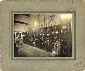
... Power House operated by The North Melbourne and Electric Tramways and Lighting Company. Photo by "Darge" Photos, 175 Collins St Melbourne, printed on the bottom right hand corner. .1 - Switchboard and wiring at the one end of the power station with attendant. .2 - View showing the engines and steam control equipment. ...Power House operated by The North Melbourne and Electric Tramways and Lighting Company. Photo by "Darge" Photos, 175 Collins St Melbourne, printed on the bottom right hand corner. .1 - Switchboard and wiring at the one end of the power station with attendant. .2 - View showing the engines and steam control equipment. ...Set of three Black and White photograph, mounted onto grey impressed and lined, brown rear, card of equipment at the Essendon or Ascot Vale Power House operated by The North Melbourne and Electric Tramways and Lighting Company. Photo by "Darge" Photos, 175 Collins St Melbourne, printed on the bottom right hand corner. .1 - Switchboard and wiring at the one end of the power station with attendant. .2 - View showing the engines and steam control equipment. (images i2 and i3 - close up of builders plate) .3 - View showing the generator ends of the engines (images i4 and i5 - close up of the buildings plate) - Browett and Lindley of Manchester, main engines. Reference photo on page 12 of "A short history of The North Melbourne Electric Tramways and Lighting Company Limited" - K.S. Kings, edited by Dean Filgate Dec. 2016.trams, tramways, power station, equipment, essendon, nmetl -
 Melbourne Tram Museum
Document - Report, Parliament of Victoria, "Report of the Royal Commission - Railway and Tramway systems on Melbourne and Suburbs", Nov. 1911
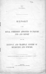
... power supply and standards, whether AC or DC, duplication, Glen Iris line, conclusions and recommendations. Tramway - summarises the current tramways operating, cable system and operational stats, the current tramway systems, other cities, relative merits, future tramways for Melbourne, operational speeds, use of cable conduits for electric traction, conversion, municipal control , control of the tramways by the railways, a general scheme, formation of a larger tramway trust and its management, purchase of the cable tramways and recommendations. ...power supply and standards, whether AC or DC, duplication, Glen Iris line, conclusions and recommendations. Tramway - summarises the current tramways operating, cable system and operational stats, the current tramway systems, other cities, relative merits, future tramways for Melbourne, operational speeds, use of cable conduits for electric traction, conversion, municipal control , control of the tramways by the railways, a general scheme, formation of a larger tramway trust and its management, purchase of the cable tramways and recommendations. ...Report - 42 pages, 3 sections, stapled on the left hand edge, titled "Report of the Royal Commission appointed to inquire into and report upon the Railway and Tramway systems on Melbourne and Suburbs" - dated 1911. Looks at the state of the Suburban rail system, finances, electrification's, costs, evidence of Mr. Merz, advantages of the electrification, power supply and standards, whether AC or DC, duplication, Glen Iris line, conclusions and recommendations. Tramway - summarises the current tramways operating, cable system and operational stats, the current tramway systems, other cities, relative merits, future tramways for Melbourne, operational speeds, use of cable conduits for electric traction, conversion, municipal control , control of the tramways by the railways, a general scheme, formation of a larger tramway trust and its management, purchase of the cable tramways and recommendations. Note: This document is available as a pdf on the Parliament of Victoria website. 2nd copy added 2-1-2019 from donation of Norm Cross.In ink in the top right hand corner "TB"trams, tramways, tramways, cable trams, finances, conversion, railways, royal commission, costs -
Federation University Historical Collection
Electrical Instrument, Analite Pty Ltd, Electric Switch Plate, c1905
... power options from a solenoid, e.g. lift operation?; light dimming? electirc switch copper brass connector variable selection analite switch plate Analite Pty Ltd, Sydney Melb underneath Numbers 1 to 4 Brass body with copper switch strips. 'Bakelite'? control buttons. Electric ...Instrument probably for variable selection of power options from a solenoid, e.g. lift operation?; light dimming?Brass body with copper switch strips. 'Bakelite'? control buttons. Electric wire screw connector.Analite Pty Ltd, Sydney Melb underneath Numbers 1 to 4 electirc switch, copper, brass, connector, variable selection, analite, switch plate -
 Melbourne Tram Museum
Photograph - Black & White, tram 867 derailed - Riversdale Road, 22/10/1976
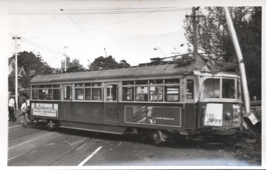
... control in Riversdale Road due to the compressor not being turned on before running out to take up a Wattle Park run. This event resulted in trams being rewired so that power to the controller could not be obtained unless the compressor had been turned on. An extract from Electric...control in Riversdale Road due to the compressor not being turned on before running out to take up a Wattle Park run. This event resulted in trams being rewired so that power to the controller could not be obtained unless the compressor had been turned on. An extract from Electric ...The photographs show SW6 tram 867 derailed at the Riversdale Road level crossing on 22/10/1976. The tram ran out of control in Riversdale Road due to the compressor not being turned on before running out to take up a Wattle Park run. This event resulted in trams being rewired so that power to the controller could not be obtained unless the compressor had been turned on. An extract from Electric Traction magazine, Nov. 1976 has been imaged. Tram 331 would have been used in rerailing. See item 7368 for The Herald report of the date.Yields information about the 1967 derailment of tram 867,Set of four Black and White photographs - printed on plain paper and digital copy of a news item.tramways, trams, mmtb, tram 867, rivesdale road, level crossings, derailments, accidents, compressors, tram 331