Showing 58 items matching "elevation detail"
-
 Friends of Ballarat Botanical Gardens History Group
Work on paper - Plans for Fencing the Ballarat Botanical Gardens, 2002, Problems With Vandalism and Theft, March, 2003
... ...ELevation Detail...John Garner Collection garner dr fence vandalism Ballarat Botanical Gardens Ballarat gardens theft Proposed Fencing Scheme Wendouree Parade Fencing ELevation Detail Adam Parrott Ballarat City Council Local Law No.6 South Gardens Boundary Lych gates Elevation detail. ...Fencing of Ballarat Botanical Gardens, because of problems with vandalism and theft. The reasons for the fencing of the Botanical Gardens are stated along with the aim to have the fencing appropriate to the style of the Gardens.2 pages. p.2 has plans on both sides of the page. Wendouree Parade fencing, p.2 and Proposed Fencing Scheme, p.3.The three pages have the Begonia logo in black and white with Ballarat Botanical Gardens superimposed and by Lake Wendouree below in smaller print.john garner collection, garner, dr, fence, vandalism, ballarat botanical gardens, ballarat, gardens, theft, proposed fencing scheme, wendouree parade fencing, elevation detail, adam parrott, ballarat city council, local law no.6, south gardens boundary, lych gates, elevation detail. -
 Falls Creek Historical Society
Plan - Diagram of Turnstile for New Chairlift
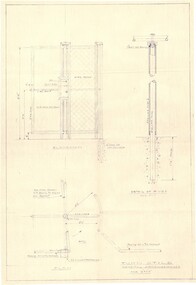
... It is a detailed plan, including elevation, detail of pivot and the general arrangement views of a turnstile. ...It is a detailed plan, including elevation, detail of pivot and the general arrangement views of a turnstile. ...Bob (Herman) Hymans (a former member of the Royal Netherlands Navy was born in Bloemendaal, Holland on 30th September 1922. During World War II he fought against the Japanese in the Dutch East Indies (now Indonesia) and was imprisoned in Changi and on the Burma Railway. After gaining qualifications as a Ski Instructor, Bob arrived in Falls Creek in May 1950. Working as an Instructor and Supervisor at Bogong Lodge, Bob decided his future was in accommodation. He was successful in negotiating an indenture for land from the State Electricity Commission (SEC). It took Bob two years to build his Grande Coeur Chalet but, tragically, it was burned down in August 1961. Bob also built the first Chairlift in Australia. This was a single chairlift and the structure was built from wooden electricity poles. He was constantly full of new ideas and proposals for the village. Bob Hymans died on 7th May 2007. This Collection of documents and letters tells the story of Bob’s endeavours to develop Falls Creek into the ski village it is today. This map is significant because it documents plans made by Bob Hymans for Falls CreekThis diagram is part of Bob Hymans documents. It is a detailed plan, including elevation, detail of pivot and the general arrangement views of a turnstile. This is part of overall plans for the construction of a new chairlift at Falls Creek. At bottom of diagrams: PLAN TURNSTILE/ GENERAL ARRANGEMENT Scale 1 1/2" = 1'- 0"map of falls creek, falls creek leases, falls creek 1980s -
 Robin Boyd Foundation
Drawing - Architectural, Robin Boyd, House at Flinders for R.J. Marriott, Aug-53
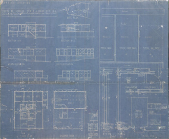
... Set of working drawings: elevations, plans, details....Set of working drawings: elevations, plans, details. Working Drawing, Blueprint (colour copy) on foamcore House at Flinders for R.J. ...Project: House at Flinders for R.J. Marriott drawn by Robin Boyd of Grounds Romberg & Boyd. Set of working drawings: elevations, plans, details.Working Drawing, Blueprint (colour copy) on foamcore -
 Orbost & District Historical Society
Plan - Large architect plans of PS Curlip and PS Nell, Adrian Brewer FLOAT A BOAT
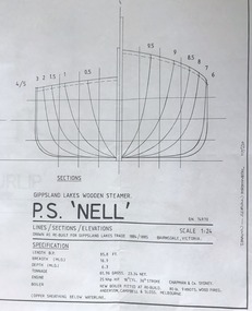
... Gippsland lakes and Snowy River wooden steamers, PS Nell and PS Curlip, deck plans, inboard elevations, sections, details. Scale 1:24 Float a Boat. ...Paddle steamer Snowy River PS Curlip PS Nell Gippsland lakes and Snowy River wooden steamers, PS Nell and PS Curlip, deck plans, inboard elevations, sections, details. Scale 1:24 Float a Boat. ...These plans by Adrian Brewer for Float a Boat are researched drawings of the PS Nell and PS Curlip both of which operated as tug boats on the Snowy River between 1880 and 1915. PS Curlip was built in 1890 by the Richardson family at Tabbara near Marlo. PS Nell operated mainly on the Gippsland lakes. Original plans and drawings for these two paddle steamers have not been found and likely do not exist. These plans are scale drawings of two of the Snowy River paddle steamers 1880 to 1915. Three scaled plan drawings. Drawn in black ink on white paper. One large plan drawing of PS Curlip and two of the PS Nell, 3370.1 and 3370.2 are of the PS Nell, 3370.3 is one plan of the PS CurlipGippsland lakes and Snowy River wooden steamers, PS Nell and PS Curlip, deck plans, inboard elevations, sections, details. Scale 1:24 Float a Boat. Adrian Brewerpaddle steamer, snowy river, ps curlip, ps nell -
 Federation University Historical Collection
Plan, Plan for the Art Deco Facade on the Ballarat School of Mines Museum, c1920
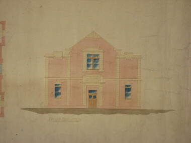
... Two hand-drawn and shaded architectural plans for the remodeling of the old Museum. .1) Plan for a new facade for the former Ballarat School of Mines Museum (formerly the Ballarat Wesleyan Church) showing front elevation. .2) Detail of front of the former Ballarat School of Mines Museum....Barker Library (top floor) Mount Helen goldfields ballarat school of mines buildings ballarat school of mines museum art deco former ballarat wesleyan church grigsby "a" hall Two hand-drawn and shaded architectural plans for the remodeling of the old Museum. .1) Plan for a new facade for the former Ballarat School of Mines Museum (formerly the Ballarat Wesleyan Church) showing front elevation. .2) Detail of front of the former Ballarat School of Mines Museum. ...Two hand-drawn and shaded architectural plans for the remodeling of the old Museum. .1) Plan for a new facade for the former Ballarat School of Mines Museum (formerly the Ballarat Wesleyan Church) showing front elevation. .2) Detail of front of the former Ballarat School of Mines Museum.ballarat school of mines, buildings, ballarat school of mines museum, art deco, former ballarat wesleyan church, grigsby, "a" hall -
 Bendigo Historical Society Inc.
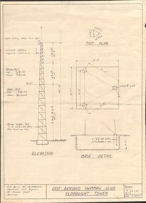
Document - BERT GRAHAM COLLECTION: PLAN OF FLOODLIGHT TOWER, 14/8/1962
... Bert Graham Collection, Bendigo East Swimming Club, Floodlight Tower, Elevation and base details, top plan, scales 1/8'', 1/2'' to 1ft.Date 14/8/62....History House 11 Mackenzie Street Bendigo goldfields BENDIGO Planning bendigo east swimming club J.E.Berry, Chartered Civil Engineer, 76 Rowan St., Bendigo Bert Graham Collection, Bendigo East Swimming Club, Floodlight Tower, Elevation and base details, top plan, scales 1/8'', 1/2'' to 1ft.Date 14/8/62. ...Bert Graham Collection, Bendigo East Swimming Club, Floodlight Tower, Elevation and base details, top plan, scales 1/8'', 1/2'' to 1ft.Date 14/8/62.J.E.Berry, Chartered Civil Engineer, 76 Rowan St., Bendigobendigo, planning, bendigo east swimming club -
Surrey Hills Historical Society Collection
Planning report, City of Boroondara, City of Boroondara planning report re 171 Union Road, Surrey Hills, 19/07/2004
... It includes attachments showing plans, elevations and details regarding objectors. The application was granted subject to additional conditions being met. ...It includes attachments showing plans, elevations and details regarding objectors. The application was granted subject to additional conditions being met. ...171 Union Road was part of the Thomas Zeplin estate. It originally had a Victorian house on it built by the Zeplin family. This was leased by Dr Percy Liddle and then Dr James Landells Blakie. Dr Blakie purchased land diagonally opposite at 174 Union Road and had a purpose-built home / surgery constructed. Later the site was occupied by COR then a BP petrol station.A detailed proposal regarding the redevelopment of the petrol station site on the corner of Union Road and Montrose Street, Surrey Hills into a 2 storey office and shop building with basement parking and access from Montrose Street. It includes attachments showing plans, elevations and details regarding objectors. The application was granted subject to additional conditions being met. union road, redevelopment, shops, town planning -
University of Melbourne, Burnley Campus Archives
Plan, Richmond Primary School 'Prep Garden', 1994
... (1) Coloured Section Elevation and Detail Suggestion by Frances Saunders August 1994. (2) Coloured Preliminary Plan, Landscape Graphics by Rachel Dann dated 16.8.94. ...University of Melbourne, Burnley Campus Archives 500 Yarra Boulevard Richmond melbourne frances saunders rachel dann julie tydens jacinta chong ian porter richmond primary school gardens Jill Kellow (1) Coloured Section Elevation and Detail Suggestion by Frances Saunders August 1994. (2) Coloured Preliminary Plan, Landscape Graphics by Rachel Dann dated 16.8.94. ...(1) Coloured Section Elevation and Detail Suggestion by Frances Saunders August 1994. (2) Coloured Preliminary Plan, Landscape Graphics by Rachel Dann dated 16.8.94. Scale 1:50. (3) Site Analysis & Inventory. Scale 1:50. (4) 2 copies, 1 coloured, Section Elevations by N. Herzberg. Scale 1:50. (5) Coloured plan, Secret Garden by Julie Tydens p3 of 3 dated 22.8.94. Scale 1:50. (6) Coloured Preliminary Plan by Jacinta Chong Sheet 3 of 3 dated 22 Aug 1994. Scale 1:100. (7) 2 tracing paper and 1 paper Site Plan drawn by JK. Scale 1:50 and 1:100. (8) Coloured Section Elevation for Landscape Graphics by Rachel Dann dated 22.08.1994. Scale 1:50. (9) Coloured Preliminary Plan dated August 1994 by Frances Saunders. Scale 1:100. (10) Preliminary Plan Sheet No 3 of 3 dated 18.08.1994 by Ian Porterfrances saunders, rachel dann, julie tydens, jacinta chong, ian porter, richmond primary school, gardens, jill kellow -
 Bendigo Military Museum
Document - GRAPH
... details. Passchendaele Barracks Trust J.W. Swatton Graph for Calculations Graph for Calculating Elevation and Clearances (Curves represent Centre Shots). ...Item in the collection re Col. J.W. Swatton. refer Cat No 6719.2P for his service details.Graph - paper, cream, black and red print, front. Reverse side, black print.Graph for Calculating Elevation and Clearances (Curves represent Centre Shots). Reverse side: Chart for .303 Mark VII for firing upon down hill.passchendaele barracks trust, j.w. swatton, graph for calculations -
 Bendigo Military Museum
Print - PRINT, FRAMED, WW1, Reader's Digest (Australia) Pty Limited, 2015
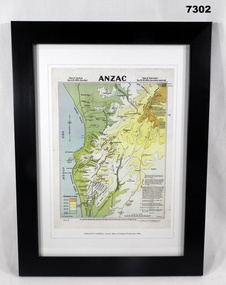
... Details below print - in black ink. "GERALD R. CAMPBELL Anzac: Map of Gallipoli Peninsula, 1916" Framed print. Print - colour print on paper. MAP ANZAC - map scale 1:10,000 elevations ...From information Book - "Readers Digest'/ Gallipoli/ 25th April 1915 - 9th January 1916/ Centenary Commemorative Prints." Collection of 20 prints. Refer Cat No. 7300.Framed print. Print - colour print on paper. MAP ANZAC - map scale 1:10,000 elevations in feet. Depicts the line of Australian and New Zealand Front Trenches. Intended as a working document. Frame - Black plastic framing with glass front and MDF board backing with adhered black paper.Details below print - in black ink. "GERALD R. CAMPBELL Anzac: Map of Gallipoli Peninsula, 1916"framed accessories, prints, ww1, gallipoli, centenary -
 Nhill Aviation Heritage Centre
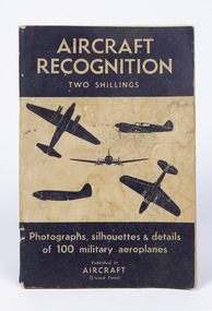
Book - Text book for trainee navigators, Edgar H. Ballie, Aircraft Recognition, Photographs, silhouettes & details of 100 military aircraft, c1940s
... details of 100 military aircraft. Two Shillings, Black and tan cover with off colour pages, black print and photos and front side and elevation view. 98 pages Aircraft Recognition, Photographs, silhouettes & details of 100 military aircraft. ...Black and tan cover with off colour pages, black print and photos and front side and elevation view. 98 pagesaircraft recognition, book, -
 Montmorency–Eltham RSL Sub Branch
Equipment - Sighting Telescope (component part)
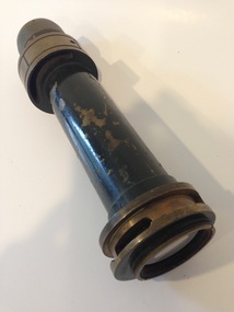
... elevation (?), ranging from 57 to 69 (see 4th picture above). Actual numbers engraved are 57 63 69, with small engravings to mark each degree between these intervals. Appears to be part of sighting telescope for artillery. Further ID information has been sought from various sources, in including the Royal Australian Artillery History Company. The RAAHC have been most cooperative and interested in attempting to identify the equipment of which this item is a part, but with no firm details ...Appears to be part of sighting telescope for artillery. Further ID information has been sought from various sources, in including the Royal Australian Artillery History Company. The RAAHC have been most cooperative and interested in attempting to identify the equipment of which this item is a part, but with no firm details on its use or history at the time of cataloguing. Detailed communication between RAAHC and MERSL are available from the latter.Off-centre ring part way along barrel has engravings for elevation (?), ranging from 57 to 69 (see 4th picture above). Actual numbers engraved are 57 63 69, with small engravings to mark each degree between these intervals. -
 Bendigo Historical Society Inc.
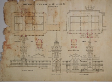
Plan - MARKS COLLECTION: PLAN FOR FOUR LEVEL STAIRCASE TOWER TO GARDEN ELEVATION AT FORTUINA VILLA FOR GEO. LANSELL ESQ
... Plan for four level staircase tower to the Garden Elevation of Fortuna Villa, Sandhurst for George Lansell Esq. Plan details: * Plan shows ground, First, second and third floor plans for the staircase construction * First and second floor house plans and location of staircase addition * Front and Garden elevations with staircase addition Plan coloured and damaged on LHS, also with water damage...Bendigo Fortuna Villa George Lansell Building plans C & T Ballerstedt Plan for four level staircase tower to the Garden Elevation of Fortuna Villa, Sandhurst for George Lansell Esq. Plan details: * Plan shows ground, First, second and third floor plans for the staircase construction * First and second floor house plans and location of staircase addition * Front and Garden elevations with staircase addition Plan coloured and damaged on LHS, also with water damage Plan MARKS COLLECTION: PLAN FOR FOUR LEVEL STAIRCASE TOWER TO GARDEN ELEVATION AT FORTUINA VILLA FOR GEO. ...Fortuna Villa was owned from 1855 to 1871 by Christopher and Theodore Ballerstedt, Australia’s first mining magnates. In 1871 it was purchased by George Lansell (The Quartz King) being one of Australia’s most successful and adventurous nineteenth century gold mine owners and speculators. Lansell made numerous alterations and extensions to the building and it remained in the Lansell family until 1935.Plan for four level staircase tower to the Garden Elevation of Fortuna Villa, Sandhurst for George Lansell Esq. Plan details: * Plan shows ground, First, second and third floor plans for the staircase construction * First and second floor house plans and location of staircase addition * Front and Garden elevations with staircase addition Plan coloured and damaged on LHS, also with water damagebendigo fortuna villa, george lansell, building plans, c & t ballerstedt -
 Bendigo Historical Society Inc.
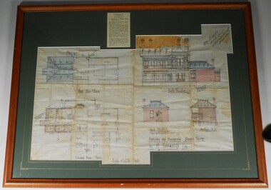
Plan - PLAN OF 'TINTEN GLEN' GOLDEN SQUARE BY WILLIAM BEEBE
... elevations and floor plan. House, called 'Tinten Glen' was owned by R. Saunders Esq. R. Saunders owned a store in High Street, Golden Square. Additions and alterations designed by William Beebe, Architect, Bendigo. On paper on top RH side " Wm Beebe, Architect, Williamson Street, Bendigo'. Top centre of framed item has a newspaper cutting displayed, detailing...elevations and floor plan. House, called 'Tinten Glen' was owned by R. Saunders Esq. R. Saunders owned a store in High Street, Golden Square. Additions and alterations designed by William Beebe, Architect, Bendigo. On paper on top RH side " Wm Beebe, Architect, Williamson Street, Bendigo'. Top centre of framed item has a newspaper cutting displayed, detailing ...Plan of additions and alterations to house in Golden Square, Bendigo. Plan mounted on green board and framed in brown timber and glass. Plan shows front and side elevations and floor plan. House, called 'Tinten Glen' was owned by R. Saunders Esq. R. Saunders owned a store in High Street, Golden Square. Additions and alterations designed by William Beebe, Architect, Bendigo. On paper on top RH side " Wm Beebe, Architect, Williamson Street, Bendigo'. Top centre of framed item has a newspaper cutting displayed, detailing the auction of the house on Saturday 6th. May ( no year ). Date 1905, confirmed on digital newspaper.bendigo, buildings, tinten glen, golden square, william beebe -
Port Melbourne Historical & Preservation Society
Plan - Entrance, Proposed Port Melbourne Library, Fred Cook, City Engineer, 12 Jan 1938
... Port Melbourne Historical & Preservation Society Port Melbourne Town Hall 333 Bay Street Port Melbourne melbourne Built Environment - Civic City Engineers Fred COOK Port Melbourne Library "Library Details":"Fred Cook City Engineer" Plan of entrance elevation City of Port Melbourne Library 1938. ...Plan of entrance elevation City of Port Melbourne Library 1938."Library Details":"Fred Cook City Engineer"built environment - civic, city engineers, fred cook, port melbourne library -
 Bendigo Historical Society Inc.
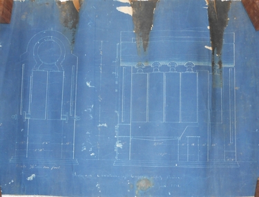
Document - MARKS COLLECTION: PLANS AND INSTRUCTIONS FOR DUPLEX SAFETY BOILER
... details of Duplex Safety Boiler. Plans are drawn on dark blue paper, backed with material. A. On bottom of plan 'Sectional elevations of Duplex Safety Boiler New York 1881' B. ...details of Duplex Safety Boiler. Plans are drawn on dark blue paper, backed with material. A. On bottom of plan 'Sectional elevations of Duplex Safety Boiler New York 1881' B. ...4 documents. Two plans showing measurements and details of Duplex Safety Boiler. Plans are drawn on dark blue paper, backed with material. A. On bottom of plan 'Sectional elevations of Duplex Safety Boiler New York 1881' B. On bottom of plan 'Plan for 50 hp Duplex Safety Boiler, ten 5ft sections' C. and D. Accompanying plans are two pages of instructions 'Directions for setting a Duplex Safety Boiler'. Written instructions in white pen on dark blue paper ( difficult to read, some faded ) 12 steps are outlined, with remarks at the bottom of the second sheet. This boiler could have been used in a Lansell mine ? (further research required).bendigo, mining, duplex safety boiler -
 Bendigo Historical Society Inc.
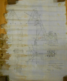
Document - MARKS COLLECTION: PLAN LANSELL'S COMET PROPRIETARY MINE BENDIGO
... detail for crusher and elevator, brick foundations. Plan is annotated with e.g. number of revolutions of jaw crusher. On bottom written in black pen: arrangement crushing and elevation plant for Lansell's Proprietary Comet Mine Bendigo, Hargreaves & Daggar, Consulting Engineers, Victoria Chambers....detail for crusher and elevator, brick foundations. Plan is annotated with e.g. number of revolutions of jaw crusher. On bottom written in black pen: arrangement crushing and elevation plant for Lansell's Proprietary Comet Mine Bendigo, Hargreaves & Daggar, Consulting Engineers, Victoria Chambers. ...Plan (engineering drawings) for construction of crushing and elevating plant at Lansell's Comet Proprietary Mine, Bendigo. Drawings show detail for crusher and elevator, brick foundations. Plan is annotated with e.g. number of revolutions of jaw crusher. On bottom written in black pen: arrangement crushing and elevation plant for Lansell's Proprietary Comet Mine Bendigo, Hargreaves & Daggar, Consulting Engineers, Victoria Chambers.mining, crushing & milling, lansell's comet mine -
 Ringwood and District Historical Society
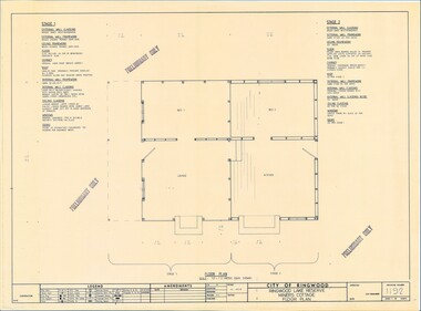
Plan - Ringwood Lake Reserve Miners Cottage - 1983, Preliminary Building Plans - 3 Sheets. Floor Plan, Elevation, Sectional Views and Details
... Floor Plan, Elevation, Sectional Views and Details Plan Ringwood Lake Reserve Miners Cottage - 1983 ...Sheets 1, 2 & 3 - Construction of replica miners cottage at Ringwood Lake Reserve, opened May, 1983.Preliminary Only -
 Flagstaff Hill Maritime Museum and Village
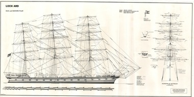
Document - Ship Model Plans, Loch Ard, October 1977
... details of specific fixtures. One slightly larger “Sail and Rigging Plan” presents a side on, above deck view of masts and shrouds and a front on, above deck view showing “Elevation of Mainmast Looking Aft”. ...details of specific fixtures. One slightly larger “Sail and Rigging Plan” presents a side on, above deck view of masts and shrouds and a front on, above deck view showing “Elevation of Mainmast Looking Aft”. ...These two framed model ship plans are from more than 650 produced for the LOCH ARD Centenary (1878-1978) Commemoration Committee. These plans were originally researched, designed and distributed in 1977 to assist entrants in the Committee’s Ship Model Competition. The competition was arranged as a means of creating public interest and awareness for the 100th anniversary of the tragic LOCH ARD shipwreck on Victoria’s south west coast in 1878. The main subject specified for modelling was “The Loch Ard ― Iron Wool Clipper 1873”. “The plans were drawn by Mr P Webb to the order of the Committee through Mr P Williams, organizer of the competition. The details were based on all available information which resulted in considerable historical research…and received favourable comment from model makers because of their attention to detail…In excess of 650 sets of plans were sold before entries closed…Many plans were probably purchased by collectors and interested persons for historical reference. An illustrated historical story sheet…was prepared and enclosed with the plans…” (‘Loch Ard Shipwreck Centenary 1878-1978 Report’, November 1978). An example of the attention to historical detail delivered on the plans is the inclusion of the following useful information about the original vessel: “Tonnage….1,693 G.R.T., 1,624 N.R.T. Builders….Charles Connell & Co., Ltd., Scotstoun, 1873. Owners….General Shipping Co., Glasgow, (Aitken Lilburn & Co., Ltd.)”. The quality of research and drafting makes these framed copies of considerable interpretive value to related items from the LOCH ARD shipwreck on display at Flagstaff Hill. They were originally mass produced but are now out of print. Flagstaff Hill retains other (unframed) copies in storage. The plans, in conjunction with the scale Ship Model of the LOCH ARD also on display, are of interpretive significance to Flagstaff Hill Maritime Village. The plans provide historical and technological context to artefacts from the shipwreck, increasing understanding and appreciation of those objects. Flagstaff Hill’s collection of artefacts from LOCH ARD is significant for being one of the largest collections of artefacts from this shipwreck in Victoria. It is significant for its association with the shipwreck, which is on the Victorian Heritage Register (VHR S417). The collection is significant because of the relationship between the objects, as together they have a high potential to interpret the story of the LOCH ARD. The LOCH ARD collection is archaeologically significant as the remains of a large international passenger and cargo ship. The LOCH ARD collection is historically significant for representing aspects of Victoria’s shipping history and its potential to interpret sub-theme 1.5 of Victoria’s Framework of Historical Themes (living with natural processes). The collection is also historically significant for its association with the LOCH ARD, which was one of the worst and best known shipwrecks in Victoria’s history. Two framed model ship plans of the LOCH ARD. These are detailed and researched plans from the original vessel, drawn to scale and printed on good quality paper, and framed behind glass to be hung on display. One slightly smaller plan “Lines, Decks and Details” portrays the hull lines as a body plan (straight on at the bow), a sheer plan (full side view), and a half breadth plan (a top-down view of deck to keel), as well as two top-down views of the upper decks and main deck with fittings and details of specific fixtures. One slightly larger “Sail and Rigging Plan” presents a side on, above deck view of masts and shrouds and a front on, above deck view showing “Elevation of Mainmast Looking Aft”. Each plan bears the draftsman’s initials and date of completion (“P.A.W. 10/77”). The larger plan also includes a boxed label attributing the project to the “LOCH ARD CENTENARY Commemoration Committee Ship Model Competition.”Smaller plan: heading “LOCH ARD: LINES, DECKS and DETAILS”; initials “P.A.W. 10/77”. Larger plan: heading “LOCH ARD: SAIL and RIGGING PLAN”; initials “P.A.W. 10/77”; label “LOCH ARD CENTENARY Commemorative Committee Ship Model Competition”. flagstaff hill, warrnambool, shipwrecked coast, flagstaff hill maritime museum, maritime museum, shipwreck coast, flagstaff hill maritime village, great ocean road, loch line, loch ard, captain gibbs, eva carmichael, tom pearce, glenample station, mutton bird island, loch ard gorge, ship model plans, loch ard model plans, sailing ship, loch ard centenary -
Federation University Historical Collection
Plan, New Engineering Building for Ballarat School of Mines, 1939, 13/06/1939
... .1) West and South Elevations .2) East and North Elecation and floor plan .3) Sections E-F, M-N, O-P, G-H, Z (Excavations and retaining walls) .4) Site plan and details of Retaining Walls .5) Excavations and retaining walls .6) Site Plan and retaining walls ...Barker Library (top floor) Mount Helen goldfields chief architect ballarat school of mines saw-tooth engineering architectural drawing .1) West and South Elevations .2) East and North Elecation and floor plan .3) Sections E-F, M-N, O-P, G-H, Z (Excavations and retaining walls) .4) Site plan and details of Retaining Walls .5) Excavations and retaining walls .6) Site Plan and retaining walls New Engineering Building for Ballarat School of Mines, 1939 Plan Plan ....1) West and South Elevations .2) East and North Elecation and floor plan .3) Sections E-F, M-N, O-P, G-H, Z (Excavations and retaining walls) .4) Site plan and details of Retaining Walls .5) Excavations and retaining walls .6) Site Plan and retaining walls chief architect, ballarat school of mines, saw-tooth, engineering, architectural drawing -
 Coal Creek Community Park & Museum
Mine Map
... 6303.1 - Cross sections of Korumburra coal mining area detailing local faulting and seam location/depth, boreholes, as well as elevation & surface topography along lines of sections....Coal Creek Community Park & Museum 12 Silkstone Road Korumburra gippsland 6303.1 - Cross sections of Korumburra coal mining area detailing local faulting and seam location/depth, boreholes, as well as elevation & surface topography along lines of sections. ...6303.1 - Cross sections of Korumburra coal mining area detailing local faulting and seam location/depth, boreholes, as well as elevation & surface topography along lines of sections. -
 Ballarat Tramway Museum
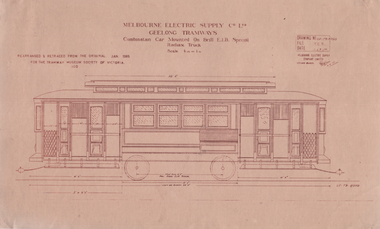
Drawing, TMSV, "Combination Car Mounted Brill E1B Special Radiax Truck", 1/1985
... Ltd (MESCo) Geelong tramways - "Combination Car Mounted Brill E1B Special Radiax Truck" - trams 16 to 23, built by Pengelley & Co in Adelaide 1924-25. Details the tramcar elevation with dimensions, and shows the towbars. ...Ltd (MESCo) Geelong tramways - "Combination Car Mounted Brill E1B Special Radiax Truck" - trams 16 to 23, built by Pengelley & Co in Adelaide 1924-25. Details the tramcar elevation with dimensions, and shows the towbars. ...Drawing of Melbourne Electric Supply Co. Ltd (MESCo) Geelong tramways - "Combination Car Mounted Brill E1B Special Radiax Truck" - trams 16 to 23, built by Pengelley & Co in Adelaide 1924-25. Details the tramcar elevation with dimensions, and shows the towbars. Drawing dated Jan 1985, prepared for the TMSV. Scale 1/4"=1' Second drawing is titled "Elevations of body Pengelley tram Nos. 20-23" - based on MESCo drawing GE-T9-8358. Drawing dated Jan 1985, prepared for the TMSV. Scale 1/4"=1' Yields information about the Pengelley built tramcars for Geelong.Set of Drawings printed on light brown paper with brown ink - Drawing GE-T9-8350 and GE-T9-8358trams, tramways, geelong, drawings, pengelley -
 Bendigo Historical Society Inc.
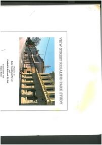
Book - View Street Rosalind Park Study, 1991
... Includes details and colour photos of shops, residences and buildings in the View St Rosalind Park precinct and elevation drawings. ...Includes details and colour photos of shops, residences and buildings in the View St Rosalind Park precinct and elevation drawings. ...258-page spiral bound book titled 'View Street Rosalind Park Study'. Includes details and colour photos of shops, residences and buildings in the View St Rosalind Park precinct and elevation drawings. Prepared by Ratio Consultants Pty Ltd and Caulfield & Krivanek Pty Ltd in association with Graeme Butler and Francine Gilfedder & Associated December 1991 Document enclosed in cardboard cover with a colour photo of part of View St.view st., rosalind park -
 Bendigo Historical Society Inc.
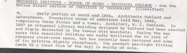
Document - National Trust Collection: Mechanics Institute - School of Mines - Technical College, & Royal Princess Hotel, 1977-1983
... Pulfer Motors Pty Ltd 3084.77p-r 12/08/1980 three sketches (site building details and street elevations) of the existing buildings on the corner of Mundy & Hargreaves Streets, Bendigo 3084.77s16/08/1980 Note advising the NTofVic of the T.A.F.E. proposal for redevelopment of the site north of Mundy Street, between McCrae and Hargreaves Sts. 3084.77t 19/08/1980 memo re: the T.A.F.E. proposal for redevelopment of the site north of Mundy Street, between McCrae and Hargreaves Sts. and existing reports 3084.77 u 11/09/1980 re: the T.A.F.E. proposal for redevelopment of the site north of Mundy Street, between McCrae and Hargreaves Sts.- local NTofVic advising "it would appear that the Urban Conservation Committee have unearthed possible options for the building so that it may be retained for its streetscape value" 3084.77va & vb 28/09/1981 from local NTofVic the Committee resolved to refer any further discussions on the Royal Princess Hoyel to the Building Committee in Central Administration.... as a result of conflicting engineering reports 3084.77wa-wd 30/10/1981 classification of the Bendigo Technical College 3084.77xa-ac 3/03/1982 from Loddon Regional TAFE Board requesting a copy of NTofVic correspondence concerning the building at the Bendigo Technology College and requesting support for the redevelopment plans for the BTC 3084.77ya-yc 14/10/1982 NTofVic urging the Government Buildings Advisory to "take action as quickly as possible"...Pulfer Motors Pty Ltd 3084.77p-r 12/08/1980 three sketches (site building details and street elevations) of the existing buildings on the corner of Mundy & Hargreaves Streets, Bendigo 3084.77s16/08/1980 Note advising the NTofVic of the T.A.F.E. proposal for redevelopment of the site north of Mundy Street, between McCrae and Hargreaves Sts. 3084.77t 19/08/1980 memo re: the T.A.F.E. proposal for redevelopment of the site north of Mundy Street, between McCrae and Hargreaves Sts. and existing reports 3084.77 u 11/09/1980 re: the T.A.F.E. proposal for redevelopment of the site north of Mundy Street, between McCrae and Hargreaves Sts.- local NTofVic advising "it would appear that the Urban Conservation Committee have unearthed possible options for the building so that it may be retained for its streetscape value" 3084.77va & vb 28/09/1981 from local NTofVic the Committee resolved to refer any further discussions on the Royal Princess Hoyel to the Building Committee in Central Administration.... as a result of conflicting engineering reports 3084.77wa-wd 30/10/1981 classification of the Bendigo Technical College 3084.77xa-ac 3/03/1982 from Loddon Regional TAFE Board requesting a copy of NTofVic correspondence concerning the building at the Bendigo Technology College and requesting support for the redevelopment plans for the BTC 3084.77ya-yc 14/10/1982 NTofVic urging the Government Buildings Advisory to "take action as quickly as possible" Document National Trust Collection: Mechanics Institute - School of Mines - Technical College, & Royal Princess Hotel ...National Trust Collection: Mechanics Institute - School of Mines - Technical College (the McCrae Street section of the Institute) A variety of correspondence from December 1977 to March 1983, between The National Trust and the Principal of the Bendigo Technical College, regarding the facade of the building, the Assay Laboratory, the Library. Various letterheaded correspondence, generally typed letters and information three site sketch plans of the buildings on the corner of Mundy and Hargreaves Streets (circa 1980). "Early portions at the northern end in 1984. Architects Vahland and Getzschmann. Foundation stone of additions laid in May 1889 comprising three floors and a tower. Architect W.C. Vahland. In 1887 an octagonal Library building designed by Vahland had been erected and finely decorated by the famous Otto Waschatz. During the war years this beautiful building was sadly mutilated due to lack of adequate classroom space but has recently been restored and some of its pristine dignity recaptured. The pendant gas-light fitting (made by a local firm of the day) is worthy of note." 3084.77a UNDATED file note Mechanics Institute - School of Mines - Technical College - now the McCrae Street section of the Institute of Technology 3084.77b&c 20/12/1977 -Bendigo Institute of Technolgy - data sheet and photographs 3084.77d citation and history of buildings 3084.77e 2/08/1978 follow up request for data information 3084.77f handwritten request from David Collins for information of the de-licensed Princess Hotel on the corner of Mundt & Hargreaves Streets 3084.77g 1/02/1980 National Trust memo requesting a site plan to show the location of the Classified Library Building in relation to the McCrae Street buildings 3084.77h 10/06/1980 from NTofVic requesting information on the various alterations and improvements proposed to the Bendigo Institute of Technology 3084.77i 29/09/1980 from NTofVic Bendigo Branch referring to proposed alterations "the matter has been referred to the Government Buildings Advisory Committee, as the buildings are now included in their register" 3084.77j 10/03/1983 from BIT Principal "for advice in designing a suitable recognition of the Royal Princess Hotel on site .....of the building and its history" 3084.77ka-d 10/08/1971 correspondence on the future of the Town Hall 3084.77l-o 12/08/1980 fwd to NTofVic re the existing building on the corner of Mundy & Hargreaves Streets, Bendigo currently occupied by W.A. Pulfer Motors Pty Ltd 3084.77p-r 12/08/1980 three sketches (site building details and street elevations) of the existing buildings on the corner of Mundy & Hargreaves Streets, Bendigo 3084.77s16/08/1980 Note advising the NTofVic of the T.A.F.E. proposal for redevelopment of the site north of Mundy Street, between McCrae and Hargreaves Sts. 3084.77t 19/08/1980 memo re: the T.A.F.E. proposal for redevelopment of the site north of Mundy Street, between McCrae and Hargreaves Sts. and existing reports 3084.77 u 11/09/1980 re: the T.A.F.E. proposal for redevelopment of the site north of Mundy Street, between McCrae and Hargreaves Sts.- local NTofVic advising "it would appear that the Urban Conservation Committee have unearthed possible options for the building so that it may be retained for its streetscape value" 3084.77va & vb 28/09/1981 from local NTofVic the Committee resolved to refer any further discussions on the Royal Princess Hoyel to the Building Committee in Central Administration.... as a result of conflicting engineering reports 3084.77wa-wd 30/10/1981 classification of the Bendigo Technical College 3084.77xa-ac 3/03/1982 from Loddon Regional TAFE Board requesting a copy of NTofVic correspondence concerning the building at the Bendigo Technology College and requesting support for the redevelopment plans for the BTC 3084.77ya-yc 14/10/1982 NTofVic urging the Government Buildings Advisory to "take action as quickly as possible"bendigo institue of technology, royal princess hotel -
 Ballarat Tramway Museum
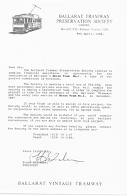
Document - Letter/s, Ballarat Tramway Preservation Society (BTPS), "Ballarat Vintage Tramway - Horse Tram No. 1 Restoration Project", Apr. 1986
... Report gives an introduction, notes on the Ballarat Horse tram service, photos, notes on the BTPS, the project itself, costings, a elevation drawing of the horse tram, operation, sponsorship details, details of the Board, costs and times, and work program and expected cash flow. 2nd copy added 6/2/2005. 2804.2 - ditto, but stapled in top right hand corner. ...Report gives an introduction, notes on the Ballarat Horse tram service, photos, notes on the BTPS, the project itself, costings, a elevation drawing of the horse tram, operation, sponsorship details, details of the Board, costs and times, and work program and expected cash flow. 2nd copy added 6/2/2005. 2804.2 - ditto, but stapled in top right hand corner. ...Set of three items concerning the restoration project for Horse Tram No. 1, by the Ballarat Vintage Tramway, 1986. 2804.1 - Letter on BTPS Letterhead, dated 8/4/1986, standard letter, seeking sponsorship or financial assistance for the project. Drafted for a Trust. Signed by the President, Frank Hanrahan. 2804.2 - 12 page report comb bound, with clear plastic cover, preprinted cover featuring horse tram No. 7 and light card rear back cover, dark blue in colour. Report gives an introduction, notes on the Ballarat Horse tram service, photos, notes on the BTPS, the project itself, costings, a elevation drawing of the horse tram, operation, sponsorship details, details of the Board, costs and times, and work program and expected cash flow. 2nd copy added 6/2/2005. 2804.2 - ditto, but stapled in top right hand corner. Images added 28/11/2016.trams, tramways, horse tram, submissions, btps, restoration -
 Ballarat Tramway Museum
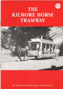
Book, William. F. Scott, "The Kilmore Horse Tramway", 1985
... Book - 12 page book with card covers, detailing the TMSV's Kilmore horse tramway operation with photographs (11), 2 side elevations of tramcars and 1 map. ...Book - 12 page book with card covers, detailing the TMSV's Kilmore horse tramway operation with photographs (11), 2 side elevations of tramcars and 1 map. ...Book - 12 page book with card covers, detailing the TMSV's Kilmore horse tramway operation with photographs (11), 2 side elevations of tramcars and 1 map. Photos B&W, side stapled with red outside cover.Price sticker "1-45" in top right hand corner.trams, tramways, horse trams, tmsv, kilmore -
 Melbourne Tram Museum
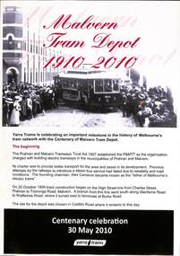
Pamphlet, Yarra Trams, "Malvern Tram Depot 1910 - 2010", "Key dates - mostly opening dates of routes", May. 2010
... Gives details of the opening, routes and the depot today. .2 - A4 printed on non glass paper, titled "Key dates - mostly opening dates of routes", list dates from 1910 to 1920, with a photo of a painting by Graham Lee of bogie car 26, side elevations of a single trucker and bogie car, and a map from "Feeding and Filling" book of the PMTT system....Gives details of the opening, routes and the depot today. .2 - A4 printed on non glass paper, titled "Key dates - mostly opening dates of routes", list dates from 1910 to 1920, with a photo of a painting by Graham Lee of bogie car 26, side elevations of a single trucker and bogie car, and a map from "Feeding and Filling" book of the PMTT system. ...Set of two pamphlets associated with the centenary of the Malvern Tram Depot in 2010. .1 - A4 full colour on gloss paper, titled "Malvern Tram Depot 1910 - 2010", advising of the background and date of the celebrations - 30/5/2010. Gives details of the opening, routes and the depot today. .2 - A4 printed on non glass paper, titled "Key dates - mostly opening dates of routes", list dates from 1910 to 1920, with a photo of a painting by Graham Lee of bogie car 26, side elevations of a single trucker and bogie car, and a map from "Feeding and Filling" book of the PMTT system.Has "May 95" in ink in top right hand corner.trams, tramways, pmtt, centenary, malvern depot, map, dates, lists, tram 26 -
 Eltham District Historical Society Inc
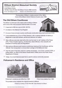
Document - Binder, Eltham Justice Precinct, 1969-2020
... Details listed include Complainant, Defendant, Fees, Cause, Decision, Remarks. Defendants listed include Edward Bettison and John McCall, N.J. Keylock [Kaylock], Patrick Clark, Michael Keenan, Ann Hayden, Henry Edelman, Alexander Falkiner, Charles Long, Joseph Morris, Daniel Ryan ii. Photocopy (2 pages) of list of Convictions for surnames commencing with ‘B’ from 23 December 1890 to December 1905. 2. Plan and elevation...Details listed include Complainant, Defendant, Fees, Cause, Decision, Remarks. Defendants listed include Edward Bettison and John McCall, N.J. Keylock [Kaylock], Patrick Clark, Michael Keenan, Ann Hayden, Henry Edelman, Alexander Falkiner, Charles Long, Joseph Morris, Daniel Ryan ii. Photocopy (2 pages) of list of Convictions for surnames commencing with ‘B’ from 23 December 1890 to December 1905. 2. Plan and elevation ...EDHS_04863 - Binder: Eltham Justice Precinct Report: Conservation Management Plan (draft) for Justice Precinct Eltham, 5 August 2005; prepared for Nillumbik Shire by Ivar Nelsen and Janette Hodgson, Land Stewardship and Biodiversity - Historic Places, Department of Sustainability and Environment 1. Courthouse 1. Eltham Courthouse interesting facts i. Photocopy (2 pages) of extract from Petty Sessions at Eltham before C.S. Strutt Esq., Chairman; and (indecipherable) on the 12th day of September 1871; Case numbers 117 to 127. Details listed include Complainant, Defendant, Fees, Cause, Decision, Remarks. Defendants listed include Edward Bettison and John McCall, N.J. Keylock [Kaylock], Patrick Clark, Michael Keenan, Ann Hayden, Henry Edelman, Alexander Falkiner, Charles Long, Joseph Morris, Daniel Ryan ii. Photocopy (2 pages) of list of Convictions for surnames commencing with ‘B’ from 23 December 1890 to December 1905. 2. Plan and elevation drawings 3. Other courthouse plans and fittings 1880s – Brunswick, Maffra, Dunolly , Sunbury, Landsborough and Wodonga 4. Newspaper articles: i. ELTHAM POLICE COURT. (1892, April 1). Evelyn Observer, and South and East Bourke Record (Vic. : 1882 - 1902), p. 2 (MORNING.). Retrieved July 5, 2022, from http://nla.gov.au/nla.news-article60667022 ii. BREAKING A PUBLICAN'S LEG. (1900, July 13). Evelyn Observer, and South and East Bourke Record (Vic. : 1882 - 1902), p. 2 (MORNING.). Retrieved July 5, 2022, from http://nla.gov.au/nla.news-article60688367 iii. ELTHAM COURT. (1901, March 1). Mercury and Weekly Courier (Vic. : 1878 - 1903), p. 3. Retrieved July 5, 2022, from http://nla.gov.au/nla.news-article58578953 iv. ANNIE CHASES A TINKER. (1902, October 3). Evelyn Observer, and South and East Bourke Record (Vic. : 1882 - 1902), p. 2 (MORNING.). Retrieved July 5, 2022, from http://nla.gov.au/nla.news-article64029968 v. ELTHAM POLICE COURT. (1927, May 6). Advertiser (Hurstbridge, Vic. : 1922 - 1939), p. 4 (AFTERNOON). Retrieved July 5, 2022, from http://nla.gov.au/nla.news-article57754748 vi. ELTHAM POLICE COURT. (1927, May 20). Advertiser (Hurstbridge, Vic. : 1922 - 1939), p. 3 (AFTERNOON). Retrieved July 5, 2022, from http://nla.gov.au/nla.news-article57754814 vii. Eltham Police Court (1931, January 9). Advertiser (Hurstbridge, Vic. : 1922 - 1939), p. 4. Retrieved July 5, 2022, from http://nla.gov.au/nla.news-article56734073 viii. Repairs to Eltham Police Station, The Advertiser (1929, May 24). Advertiser (Hurstbridge, Vic. : 1922 - 1939), p. 2 (AFTERNOON.). Retrieved July 5, 2022, from http://nla.gov.au/nla.news-article57759907 ix. ELTHAM COURT. (1929, August 2). Advertiser (Hurstbridge, Vic. : 1922 - 1939), p. 4 (AFTERNOON.). Retrieved July 5, 2022, from http://nla.gov.au/nla.news-article57760345 x. See also Trove list https://trove.nla.gov.au/list/116634 5. Letter: Shire of Eltham Historical Society to Shire of Eltham, 1 July 1969 regarding potential replacement of Eltham Courthouse and the building’s historical significance and acknowledgement 10 July 1969 6. Letter: Shire of Eltham Historical Society to Law Department, 26 May 1972, re preservation of Eltham Courthouse and potential classification and acknowledgement 7 June 1972 7. Newspaper article: Strangers around, so Eltham sought protection by Marguerite Marshall, Diamond Valley News, Tuesday, April 6, 1982, p2 (On reverse side, Top job for our Pauline, p1) 8. Eltham Courthouse Colour Scheme, Public Works Department, 10 September 1983 9. Newspaper article: Eltham Courthouse under threat of closure by Helen Gillman, Diamond Valley News, October 16, 1984 10. Newspaper article: Courthouse to close by Helen Gillman, Diamond Valley News, Tuesday, November 20, 1984, p1 (also on p2 an article about Diamond Valley Shire festivities for the State’s 150th) 11. We will keep your court – Kennett, Diamond Valley News (probable), c.Dec. 1984 12. Letter: Shire of Eltham to Shire of Eltham Historical Society, 15 March 1985, regarding potential for use of building as a museum and reply dated 17 April 1985 regarding Society’s interest in use of the building 13. Letter: Department of Conservation Forests & Lands to Shire of Eltham, August 1987, regarding expressions of interest in the building and letter from Shire (18 August 1987) to Society advising of same 14. Letter: Department of Conservation Forests & Lands to Shire of Eltham, 30 March 1988, advising Courthouse to be used by Eltham Youth Resources Centre and the rear section by other community groups. Noted that the historical society was suggested by Council as a future user of the adjoining police residence when Council first sought management of the building and that should be investigated. Includes Schedule of Repair and Maintenance Work (4 pages), Existing Conditions Survey 30/7/1987 (6 pages) and 1 page plan view diagram 15. Memo: Historic Places Section to Eltham Youth Resource Centre re paint analysis of Courthouse, 17/5/1988, (6 pages) 16. Newspaper article: Courthouse renovation by Jodie Haythorne, Diamond Valley News, November 23, 1992 17. National Trust of Australia Registration (classified 20 Oct 1977), printed March 2000 18. Letter: Heritage Victoria 28 Feb 2002 regarding the replacement of the Courthouse Stand (Witness Box) 19. Article: There’s still order in this stately court house, Eltham Shire (magazine), date unk., p22-23 20. Eltham Court House, Statement of Significance, Heritage Victoria Register, printed Nov 2004 21. Eltham 1860 Former Court House 730 Main Road Eltham, collated by Eltham District Historical Society Incorporated 2005 (4 pages) 22. Book Extract: Eltham, Historical Court Houses of Victoria by Michael Challinger, Palisade Press, 2001 23. Newspaper article: Courthouse rich with history by Harry Gilham, Nillumbik Mail, c.2001 (see also EDHS_03333) 24. Notes on history of site from Crown Reserve File Rs 12128, Municipal Buildings (Local Community Welfare Reserve) at Eltham, Department of Sustainability and Environment, April 2005 (4 pages) 25. Newspaper article: Historic building upgrade, Diamond Valley Leader, August 3, 2005, p17 26. Newspaper article: Courthouse regeneration secures boost, Valley Weekly, August 10, 2005 with picture of Harry Gilham, Steve Herbert and Greg Johnson 27. Newspaper article: Poets are summonsed, Diamond Valley Leader February 22, 2006, p37 features picture of Helen Lucas at the Eltham Courthouse 28. Newspaper article: Sharing a love of legalities, Diamond Valley Leader, March 1, 2006, p7 features a picture of Rob Hulls and Steve Herbert talking to students in the courthouse 29. Newspaper advertisement: Nillumbik Tender No. 2021-33, Building Restoration Works, Old Eltham Courthouse, The Age, November 7, 2020 30. Form: Police Officer’s Return To A Warrant Of Distress 31. Handwritten notes: three pages listing all 48 of the pigeon hole form listings in the cabinet in the courthouse 32. Newspaper article: Historic Eltham Courthouse reopens, Manningham and Nillumbik Bulletin, April 2022, p22 33. Expression of Interest, Eltham Courthouse, 730 Main Road, Eltham; Nillumbik Shire Council Living and Learning Centres Eltham & Panton Hill, 8 May 2000 (Committee of Management) 2. Police Quarters 1. 1971 Surveyors Plan of 728 Main Road and the Adjoining Courthouse. Also includes notes (1963) on Lots 4 and 5 southeast corner of Main Road and Brougham Street owned by James Wallace Graham, Contractor, and Elsie May Graham. 2. Letter: Shire of Eltham to Shire of Eltham Historical Society, 5 June 1981, requesting the society give consideration to the suitability of the existing buildings (former Vermin and Noxious Weeds Office, Department of Crown Lands and Survey) for historical purposes such as a museum 3. Minutes: Shire of Eltham Historical Society Committee Meeting, 10 June 1981 (2 pages) includes reference to possible use of building as a museum (also reference to Bills Horse trough to be retained) 4. Extract from Victoria Police Gazette 1930 with details of building and site 5. Newspaper article: Cubby haven, Diamond Valley News, October 28, 1991 about replica Police Station with picture of replica along with Monika Roitinger and Garry Bartlett outside the Police Station 6. Environment office up for sale? Mountain Views, Monday, June 12, 1995 (Nillumbik Shire Council proposing to sell property. Did not proceed as ownership held by the State of Victoria) 7. Extract from National Trust February 1998 edition, “Police Rescue” which states Heidelberg and Eltham Police Residences are the oldest known Police Residences in the Melbourne Metropolitan district 8. Newspaper article: The first police office by Harry Gilham, Nillumbik Mail, December 13, 2000 (also photocopy with notations on picture identifying buildings and Harry’s typed draft) 9. Fax Memo: Victoria Police List of Officers in Charge, Eltham Police Station, 1857-1991 onward, 21 Jan 2003 10. Former Police Quarters, Statement of Significance, Heritage Victoria Register, printed Nov 2004 11. Eltham 1860 Former Police Quarters 728 Main Road Eltham, collated by Eltham District Historical Society Incorporated 2005 (5 pages) 12. Report: Eltham District Historical Society to Living and Learning Nillumbik, 14 April 2010 regarding the poor state of condition of the former Police Residence 13. Photocopy of three photos of the former Police Residence, former Police Station (relocated to rear of site) and Stables, October 18, 1991 3. Lockup 1. Newspaper article: Heritage permit bid, Diamond Valley News, January 17, 2001 (also article “Eltham library tops”) includes picture of lockup located in Youth Road 2. Newspaper article: Old lockup in new site, Diamond Valley Leader, March 21, 2001, p15. Includes picture of Harry Gilham with lockup at justice Precinct 3. Letter: Victoria Police to Eltham District Historical Society, 20 March 1991 including laser print photo of lockup in 1963 at 23 Pryor Street 4. Fax: Graham Clark, Associated Crane Trucks Pty Ltd, 833 Main Road Hurstbridge; Quote 26.2.99 for $1,080 to move lockup from Youth Road to 728 Main Road 4. Local History Centre 1. Victoria Government Gazette: Photocopy, No. 165, Tuesday, December 7, 1858, establishment of a Court of Petty Sessions at Eltham, 7 December 1858 2. Victoria Government Gazette: Photocopy, September 16, 1859, contract issued for Police buildings at Eltham to Langridge and Co., McCarter, Baillie, Nicol and Co, Chadley, Amos and Co., Cameron, Payne, £1,150.7.0 3. Victoria Government Gazette: Photocopy, October 2, 1860, contract issued for Court of Petty Sessions at Eltham to James Duncan, £600 4. President’s Report, Eltham District Historical Society, Annual General Meeting, Wednesday, March 11, 1998 – covers the establishment of the Local History Centre and new home for the Society 5. Extract for EDHS Newsletter July 1998 – Eltham Local History Centre – Official Opening 6. Unveiling of 728 Street Sign, Speech notes by Cr Dianne Bullen, December 2000, includes invoice from John Sharp Signs Pty Ltd, 24/10/2000 and planning approval drawing dated 24/3/1999 reproduced in Newsletter No. 135 November 2000 7. Letter: Eltham District Historical Society to Living and Learning Centre, undated draft regarding being a member of the committee reviewing the development of the site 8. Notes from Rod Grant re funding of site development under the Community Jobs Program 9. Letter: Eltham District Historical Society to Nillumbik Living and Learning, 28 October 2004 re inclusion of the Society in enhancing the site under the Community Jobs Program 10. Letter: Department of Sustainability and Environment to Eltham District Historical Society, 28 February 2005 re preparing draft Conservation Plan and copy of cover letter in response 2 April 2005 11. Levels and Layout Plan, Nillumbik Shire Council, September 2005, AO copy 12. Letter: Department of Sustainability and Environment to Eltham District Historical Society, 12 September 2005 re Eltham Justice Precinct Conservation Management Plan 13. Letter: Living and Learning Nillumbik, 2 February 2006 to Eltham District Historical Society re forming a Committee to advise on the use, maintenance, management and preservation of the Justice Precinct 14. Minutes: Meeting of a Task group to explore the establishment of a Committee to manage the Eltham Justice Precinct, 20 December 2005 (with hand written notes) 15. President’s notes (EDHS), General Meeting item, 11 May 2006 pertaining to use and condition of the Eltham Justice Precinct 16. Paint estimates, Old Eltham Court House, undated 17. Notes from meeting 26 September (2006), Eltham Justice Precinct Committee 18. Notes from meeting 27 November (2006), Eltham Justice Precinct Committee 19. Terms of Reference for the Eltham Justice Precinct Committee, Draft for Living and Learning Committee Meeting 24 Jan 2007 (4 pages) 20. Newspaper article: Panel set up, Diamond Valley Leader, 7 March 2007 21. Minutes: Meeting of Eltham Justice Precinct Subcommittee, 10 May 2007 22. Minutes: Meeting of Eltham Justice Precinct Subcommittee, 5 July 2007 23. Minutes: Meeting of Eltham Justice Precinct Subcommittee, 11 October 2007 24. Minutes: Meeting of Eltham Justice Precinct Subcommittee, 7 February 2008 25. Minutes: Meeting of Eltham Justice Precinct Subcommittee, 10 April 2008 26. Minutes: Meeting of Eltham Justice Precinct Subcommittee, 14 August 2008 27. Letter: EDHS (Sue Law) to Living and Learning, 6 September 2008 re proposed signage 28. Agenda: Meeting of Eltham Justice Precinct Subcommittee, 16 October 2008 29. Suggested guidelines for use of the Court House for exhibitions 30. Handwritten note re Ken Eckersal and Uniting Church of possible donation of church organ for sale, proceeds to be used for activities at the Justice precinct 31. One page typed notes on each of the buildings in the Eltham Justice Precinct 32. Newspaper article: Historic Eltham Courthouse reopens, Manningham and Nillumbik Bulletin, April 2022, p22 5. Miscellaneous 1. Photocopy from Pioneers & Painters (2 pages) covering the establishment of Police and Court of Petty Sessions at Eltham 2. Photocopy of photo looking northeast across Little Eltham buildings c.1910 with notes 3. Photocopy of J.H Clarke photo looking up Maria Street from near Dalton Street with notes identifying precinct buildings 4. Photocopy of photo of Court House and Police Quarters with cow outside from Heather Jenkins scrapbook with notes identifying buildings 5. Sketch and notes with dimensions for blue stone lockup including other miscellaneous handwritten notes 6. Unidentified heritage review details of Justice Precinct (c.2004) 7. Hand written notes of telephone conversation held with Dennis McKay (6 May 1997) re Council use of site 8. Flyer: Victoria Police Historical Unit 9. Photocopy of thumbnail images of various Justice Precincts (not identified) 10. Email correspondence, 4 and 10 January 2008; J. Connor to Council and Councillors pertaining to proposed new toilet facilities at rear of Courthouse annexe. Two ring lever arch binder, white with various photocopies, printouts, newspaper clippingsHG Folders 15/52/59 integratedharry gilham collection, eltham courthouse, eltham justice precinct, eltham police residence, lockup, eltham community festival, eltham festival, eltham, heritage assessment, police residence, conservation, alexander falkiner, ann hayden, charles long, court of petty sessions, daniel ryan, edward bettison and john mccall, eltham court house, henry edelman, joseph morris, michael keenan, n.j. kaylock, patrick clark, elsie may graham, franco and co, james wallace graham, surveyor field notes -
 Ballarat and District Irish Association
Photograph - Colour, Clare Gervasoni, St Patrick's Cathedral Hall, Ballarat, 2007, 20/11/2007
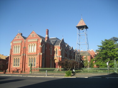
... detailing. The main hipped roof of the hall is intersected on both sides by four gables, and the front ridge is intersected by two further gables to form the street elevation. ...detailing. The main hipped roof of the hall is intersected on both sides by four gables, and the front ridge is intersected by two further gables to form the street elevation. ...St Patrick's Cathedral Hall was erected in 1900 to the architectural plans of Clegg, Kell and Miller. The builder was Peter Bodger. The Cathedral Hall is a massive structure in the Gothic manner, with slender proportions and Gothic window detailing. The main hipped roof of the hall is intersected on both sides by four gables, and the front ridge is intersected by two further gables to form the street elevation. Internally the hall resembles many town halls except for the two tiers of Gothic windows and the manner in which the ceiling curves downward towards the walls. Pointed Gothic windows on the upper level intersect the curved ceiling in a simple groined junction. The plaster ceiling is coffered by intersecting beams, while a central skylight floods the hall with natural light. Other features of note are the ridging on the front gables, and the iron bell tower framed in steel angles and braced with criss-crossed rods, complete with a huge wheel and a great bell. St Patrick's Hall demonstrates a notable application of decorative schemes, particularly its highly decorated ceiling which has few parallels amongst other church halls in Victoria. The hall is in an important location as part of St Patrick's complex, as well as part of the group of churches which include St Andrew's Kirk and the former Baptist Church, opposite in Dawson Street. (http://stpatscathedral.weebly.com/cathedral-hall--presbytery.html, accessed 13 November 2013.A series of colour digital photographs showing a large red brick hall associated with St Patrick's Cathedral, Ballarat. The bell tower is situated to the right of the hall.ballarat irish, st patrick's cathedral hall, cathedral hall ballarat, bell, bell tower -
Stawell Historical Society Inc
Archive, Plans from the Dept. Works Ararat
... Archive 4262 Plans For Pleasent Creek 4262 - Existing Plans for Pleasent Creek 4262A - 2A Bellfield Unit 4262B - 2B Fyans Unit 4262C - 2C Nurses Unit 4262D - Biala Unit 4262E - Hostel Unit 4262F - Residence 3 & 4 (X2) 4262G - Residence 5 & 6 4262H - Nara Unit 4262I - Syme Unit 4262J - Lonsdale Unit 4262K - School Buildings 4262L - Recreation Building 4262M - Administration Building 4262N - Alexandra Building 42620 - L.T.O. building 4262P - Engineers Workshop & Laundry 4262Q - Sewing Room & Stores 4262R - Carpenters, Painters & Gardener's Workshops 4262S - 3 Existing Plans for Pleasent Creek Centre Stawell & Emergency Water Legend 4262T - 7 Existing Plans for Plesent Creek Stawell Centre Stawell Inc: Grid Squares 4262-1 73.5 X 56 CM Sheet No.1 New Dining Room Special School Amended Setout of Windows 4262-1A - 73.5 X 56 CM Sheet No. 2 Special School Stawell Joiners details 4262-1B - 73.5 X 56 CM Sheet No. 3 Pleasant Creek School: New Dining Room 4262-1C -73.5 X 56 CM Sheet No. 4 Pleasant Creek School Joinery details 4262-1D - 73.5 X 56 CM Sheet No. 5 Pleasant Creek School Joinery Details 4262-1E - 48 X 39 CM Section AA Pleasant Creek School Dining Room Stainless Steel Sinks & Drains 4262 -1F 50 X 69X5 CM School for Subnormal Children - Stawell Mental Hospital Elvation and Accordion 4262-1G 56 X 40 CM Sheet 6 Stawell Pleasant Creek School - Joinery Detail 4262-1H 75 X 54 CM Stawell Pleasant Creek School - Detail of Serving Window 4262 -1I 75 X 54 CM Stawell Hospital for the Insane - Cills to Windows, Store and soon to be Male Division 4262 -1J 50.5 X 24 CM Stawell Pleasant Creek School - deatils of Serving Window 4262 -2 39 X 34 CM Concongella School 1136 Sundry Works etc. 4262-2A 20 X 35 CM State School 1702 Joel Joel - Remodeling & Repairs Painting etc. 4262-2B 36 X 44.5 CM Mokepilly School Remodelling 4262-2C 21 X 34 CM 2951 Marnoo East - Sketch of Proposed Cloak Room 4262-2D 21 X 34 CM SS 2951 Marnoo East Elevation Showing New Cloak Room 4262-2E 40 X 39 CM Additions & Alterations to Concongella School 1136 4262-2F 21.3 X 33.5 CM School 2951 Marnoo East Elvation and Ground Plan 4262-2G 38 X 33.5 CM School 1554 Marnoo & Residence 4262-2H 21.5 33.5 CM Marnoo SS No 1554 Repairs and Painting 4262-2I 205 X 32 CM Marnoo School 1554 Alternative Drawingsfor building In Brick 4262-2J 50 X 43.5 CM New Concrete School 1554 Marnoo 4262-2K 62 X 56 CM Removal & Alterations to Marnoo's School No. 1554 4262-2L 49.5 X 33.5 CM Great Western School 860 - Teacher's Residence 4262-2M 20.5 X 33.5 CM Great western School 860 - Elevation & Ground Plan 4262-2N 20.5 X 33.5 CM Great Western School 860 - Shelter Sheds & Tank Stand 4262-2O 25.5 X 30 CM Great Western School 860 - Floor Plan 4262-2P 20 X 34 CM Residence to Great Western Schhool - Plastering & Painting etc,. 4262-2Q 59 X 50.5 CM Great Western School860 - Additions 4262-2R 21 X 33 CM Plan school 263 Glenorchy 4262-2S 21 X 33 CM Plan School 263 Glenorchy 4262-2T 35 X 38 CM Glenorchy School 263 Remodelling etc,. to Teacher's Residence 4262-2U 33.5 X 22 CM Repairs & Repainting School & Residence Glenorchy SS 263 4262-2V 53 X 34 CM Proposed Sleepout for Teachers Residence Glenorchy School 4262-2W 53.5 38 CM Glenorchy School No. 263 and Residence Raising School buildings etc,. 4262-2X 29 x 56 CM Glenorchy School 263 New Cloak Room etc. 4262-3 22 X 31 CM Drawing of Part of Builing 4262-3A 35 X 46 CM Stawell Roof Plan & Side Elevation 4262-3B 48 X 65 CM State School Drawing No 1 4262-3C 32 X 27 CM Renewal of Existing water Supply 4262-3E 61 X 40 CM Stawell Infant State School 503 - External Repairs & Renovations 4262-3F 48.5 X 53 CM Education Department Stawell State School Drawig No 2 Contract 181 4262-3G 73 X 55 CM Alterations & Additions S.S. 502 Stawell Drawing No.1 4262-3H 73 X 55 CM Alterations & Additions S.S. 502 Stawell Drawing No.2 4242-3I 73 X 55 CM Alterations & Additions S.S. 502 Stawell Drawing No.3 4262-3J 56 X 34 CM State School 502 Plan Clarifying & Chlorinating Chamber 4262-3K 33 X 21 CM Part Ground Plan StawellSchool 502 - Accordion Doors etc. 4262-3L 60 X 54 CM Accordion Door details for School at Stawell 502 4262-3M 69 X 52 CM Stawell State School No 502 External repairs - Renovations 4262-3N 72 X 55 CM Altereed & Additions State School 502 Drawing No 1 4262-30 35 X 21 CM Stawell School 502 New Wood Shed etc 4262-3P 68 X 34 CM Main School - New Gutters shown thus. ...Stawell Historical Society Inc 46 Longfield St Stawell grampians Archive 4262 Plans For Pleasent Creek 4262 - Existing Plans for Pleasent Creek 4262A - 2A Bellfield Unit 4262B - 2B Fyans Unit 4262C - 2C Nurses Unit 4262D - Biala Unit 4262E - Hostel Unit 4262F - Residence 3 & 4 (X2) 4262G - Residence 5 & 6 4262H - Nara Unit 4262I - Syme Unit 4262J - Lonsdale Unit 4262K - School Buildings 4262L - Recreation Building 4262M - Administration Building 4262N - Alexandra Building 42620 - L.T.O. building 4262P - Engineers Workshop & Laundry 4262Q - Sewing Room & Stores 4262R - Carpenters, Painters & Gardener's Workshops 4262S - 3 Existing Plans for Pleasent Creek Centre Stawell & Emergency Water Legend 4262T - 7 Existing Plans for Plesent Creek Stawell Centre Stawell Inc: Grid Squares 4262-1 73.5 X 56 CM Sheet No.1 New Dining Room Special School Amended Setout of Windows 4262-1A - 73.5 X 56 CM Sheet No. 2 Special School Stawell Joiners details 4262-1B - 73.5 X 56 CM Sheet No. 3 Pleasant Creek School: New Dining Room 4262-1C -73.5 X 56 CM Sheet No. 4 Pleasant Creek School Joinery details 4262-1D - 73.5 X 56 CM Sheet No. 5 Pleasant Creek School Joinery Details 4262-1E - 48 X 39 CM Section AA Pleasant Creek School Dining Room Stainless Steel Sinks & Drains 4262 -1F 50 X 69X5 CM School for Subnormal Children - Stawell Mental Hospital Elvation and Accordion 4262-1G 56 X 40 CM Sheet 6 Stawell Pleasant Creek School - Joinery Detail 4262-1H 75 X 54 CM Stawell Pleasant Creek School - Detail of Serving Window 4262 -1I 75 X 54 CM Stawell Hospital for the Insane - Cills to Windows, Store and soon to be Male Division 4262 -1J 50.5 X 24 CM Stawell Pleasant Creek School - deatils of Serving Window 4262 -2 39 X 34 CM Concongella School 1136 Sundry Works etc. 4262-2A 20 X 35 CM State School 1702 Joel Joel - Remodeling & Repairs Painting etc. 4262-2B 36 X 44.5 CM Mokepilly School Remodelling 4262-2C 21 X 34 CM 2951 Marnoo East - Sketch of Proposed Cloak Room 4262-2D 21 X 34 CM SS 2951 Marnoo East Elevation Showing New Cloak Room 4262-2E 40 X 39 CM Additions & Alterations to Concongella School 1136 4262-2F 21.3 X 33.5 CM School 2951 Marnoo East Elvation and Ground Plan 4262-2G 38 X 33.5 CM School 1554 Marnoo & Residence 4262-2H 21.5 33.5 CM Marnoo SS No 1554 Repairs and Painting 4262-2I 205 X 32 CM Marnoo School 1554 Alternative Drawingsfor building In Brick 4262-2J 50 X 43.5 CM New Concrete School 1554 Marnoo 4262-2K 62 X 56 CM Removal & Alterations to Marnoo's School No. 1554 4262-2L 49.5 X 33.5 CM Great Western School 860 - Teacher's Residence 4262-2M 20.5 X 33.5 CM Great western School 860 - Elevation & Ground Plan 4262-2N 20.5 X 33.5 CM Great Western School 860 - Shelter Sheds & Tank Stand 4262-2O 25.5 X 30 CM Great Western School 860 - Floor Plan 4262-2P 20 X 34 CM Residence to Great Western Schhool - Plastering & Painting etc,. 4262-2Q 59 X 50.5 CM Great Western School860 - Additions 4262-2R 21 X 33 CM Plan school 263 Glenorchy 4262-2S 21 X 33 CM Plan School 263 Glenorchy 4262-2T 35 X 38 CM Glenorchy School 263 Remodelling etc,. to Teacher's Residence 4262-2U 33.5 X 22 CM Repairs & Repainting School & Residence Glenorchy SS 263 4262-2V 53 X 34 CM Proposed Sleepout for Teachers Residence Glenorchy School 4262-2W 53.5 38 CM Glenorchy School No. 263 and Residence Raising School buildings etc,. 4262-2X 29 x 56 CM Glenorchy School 263 New Cloak Room etc. 4262-3 22 X 31 CM Drawing of Part of Builing 4262-3A 35 X 46 CM Stawell Roof Plan & Side Elevation 4262-3B 48 X 65 CM State School Drawing No 1 4262-3C 32 X 27 CM Renewal of Existing water Supply 4262-3E 61 X 40 CM Stawell Infant State School 503 - External Repairs & Renovations 4262-3F 48.5 X 53 CM Education Department Stawell State School Drawig No 2 Contract 181 4262-3G 73 X 55 CM Alterations & Additions S.S. 502 Stawell Drawing No.1 4262-3H 73 X 55 CM Alterations & Additions S.S. 502 Stawell Drawing No.2 4242-3I 73 X 55 CM Alterations & Additions S.S. 502 Stawell Drawing No.3 4262-3J 56 X 34 CM State School 502 Plan Clarifying & Chlorinating Chamber 4262-3K 33 X 21 CM Part Ground Plan StawellSchool 502 - Accordion Doors etc. 4262-3L 60 X 54 CM Accordion Door details for School at Stawell 502 4262-3M 69 X 52 CM Stawell State School No 502 External repairs - Renovations 4262-3N 72 X 55 CM Altereed & Additions State School 502 Drawing No 1 4262-30 35 X 21 CM Stawell School 502 New Wood Shed etc 4262-3P 68 X 34 CM Main School - New Gutters shown thus. ...Archive 4262 Plans For Pleasent Creek 4262 - Existing Plans for Pleasent Creek 4262A - 2A Bellfield Unit 4262B - 2B Fyans Unit 4262C - 2C Nurses Unit 4262D - Biala Unit 4262E - Hostel Unit 4262F - Residence 3 & 4 (X2) 4262G - Residence 5 & 6 4262H - Nara Unit 4262I - Syme Unit 4262J - Lonsdale Unit 4262K - School Buildings 4262L - Recreation Building 4262M - Administration Building 4262N - Alexandra Building 42620 - L.T.O. building 4262P - Engineers Workshop & Laundry 4262Q - Sewing Room & Stores 4262R - Carpenters, Painters & Gardener's Workshops 4262S - 3 Existing Plans for Pleasent Creek Centre Stawell & Emergency Water Legend 4262T - 7 Existing Plans for Plesent Creek Stawell Centre Stawell Inc: Grid Squares 4262-1 73.5 X 56 CM Sheet No.1 New Dining Room Special School Amended Setout of Windows 4262-1A - 73.5 X 56 CM Sheet No. 2 Special School Stawell Joiners details 4262-1B - 73.5 X 56 CM Sheet No. 3 Pleasant Creek School: New Dining Room 4262-1C -73.5 X 56 CM Sheet No. 4 Pleasant Creek School Joinery details 4262-1D - 73.5 X 56 CM Sheet No. 5 Pleasant Creek School Joinery Details 4262-1E - 48 X 39 CM Section AA Pleasant Creek School Dining Room Stainless Steel Sinks & Drains 4262 -1F 50 X 69X5 CM School for Subnormal Children - Stawell Mental Hospital Elvation and Accordion 4262-1G 56 X 40 CM Sheet 6 Stawell Pleasant Creek School - Joinery Detail 4262-1H 75 X 54 CM Stawell Pleasant Creek School - Detail of Serving Window 4262 -1I 75 X 54 CM Stawell Hospital for the Insane - Cills to Windows, Store and soon to be Male Division 4262 -1J 50.5 X 24 CM Stawell Pleasant Creek School - deatils of Serving Window 4262 -2 39 X 34 CM Concongella School 1136 Sundry Works etc. 4262-2A 20 X 35 CM State School 1702 Joel Joel - Remodeling & Repairs Painting etc. 4262-2B 36 X 44.5 CM Mokepilly School Remodelling 4262-2C 21 X 34 CM 2951 Marnoo East - Sketch of Proposed Cloak Room 4262-2D 21 X 34 CM SS 2951 Marnoo East Elevation Showing New Cloak Room 4262-2E 40 X 39 CM Additions & Alterations to Concongella School 1136 4262-2F 21.3 X 33.5 CM School 2951 Marnoo East Elvation and Ground Plan 4262-2G 38 X 33.5 CM School 1554 Marnoo & Residence 4262-2H 21.5 33.5 CM Marnoo SS No 1554 Repairs and Painting 4262-2I 205 X 32 CM Marnoo School 1554 Alternative Drawingsfor building In Brick 4262-2J 50 X 43.5 CM New Concrete School 1554 Marnoo 4262-2K 62 X 56 CM Removal & Alterations to Marnoo's School No. 1554 4262-2L 49.5 X 33.5 CM Great Western School 860 - Teacher's Residence 4262-2M 20.5 X 33.5 CM Great western School 860 - Elevation & Ground Plan 4262-2N 20.5 X 33.5 CM Great Western School 860 - Shelter Sheds & Tank Stand 4262-2O 25.5 X 30 CM Great Western School 860 - Floor Plan 4262-2P 20 X 34 CM Residence to Great Western Schhool - Plastering & Painting etc,. 4262-2Q 59 X 50.5 CM Great Western School860 - Additions 4262-2R 21 X 33 CM Plan school 263 Glenorchy 4262-2S 21 X 33 CM Plan School 263 Glenorchy 4262-2T 35 X 38 CM Glenorchy School 263 Remodelling etc,. to Teacher's Residence 4262-2U 33.5 X 22 CM Repairs & Repainting School & Residence Glenorchy SS 263 4262-2V 53 X 34 CM Proposed Sleepout for Teachers Residence Glenorchy School 4262-2W 53.5 38 CM Glenorchy School No. 263 and Residence Raising School buildings etc,. 4262-2X 29 x 56 CM Glenorchy School 263 New Cloak Room etc. 4262-3 22 X 31 CM Drawing of Part of Builing 4262-3A 35 X 46 CM Stawell Roof Plan & Side Elevation 4262-3B 48 X 65 CM State School Drawing No 1 4262-3C 32 X 27 CM Renewal of Existing water Supply 4262-3E 61 X 40 CM Stawell Infant State School 503 - External Repairs & Renovations 4262-3F 48.5 X 53 CM Education Department Stawell State School Drawig No 2 Contract 181 4262-3G 73 X 55 CM Alterations & Additions S.S. 502 Stawell Drawing No.1 4262-3H 73 X 55 CM Alterations & Additions S.S. 502 Stawell Drawing No.2 4242-3I 73 X 55 CM Alterations & Additions S.S. 502 Stawell Drawing No.3 4262-3J 56 X 34 CM State School 502 Plan Clarifying & Chlorinating Chamber 4262-3K 33 X 21 CM Part Ground Plan StawellSchool 502 - Accordion Doors etc. 4262-3L 60 X 54 CM Accordion Door details for School at Stawell 502 4262-3M 69 X 52 CM Stawell State School No 502 External repairs - Renovations 4262-3N 72 X 55 CM Altereed & Additions State School 502 Drawing No 1 4262-30 35 X 21 CM Stawell School 502 New Wood Shed etc 4262-3P 68 X 34 CM Main School - New Gutters shown thus. State School 502 Stawell Renewals Eaves Guttering 4262-3Q 58 X 34 CM State School No 502. Stawell Block Plan 4262-3R 73 X 55 CM State School 502 Drawing No.2 4262-4 99 X 79 CM State of Victoria Public Works Department - Layout of heating System Administration Block and Toddlers Playroom. Pleasant Creek special School (2 Copies) 42624A 86 X 89.5 CM Existing Layout of Peasnt Creek Centre Fire Service Water Mains 4262-4B 87X 59.5 CM Department of Human Services Victoria Emergancy Schematic Palns Pleasant Creek Centre ( Plans also in 4262 & 4262-1?) Cover Sheet. Former Pleasant Creek Hospital site. Sometimes referred to as Pleasant Creek Special School and sometimes Pleasant Creet Training Centre.Plans of Schools and other Buildings