Showing 17 items matching "rod holder"
-
 Ballarat Base Hospital Trained Nurses League
Rod Holder for Tonsillectomy
... Rod Holder for Tonsillectomy...Rod Holder...Ballarat Base Hospital Trained Nurses League Drummond Street Nth Ballarat goldfields Rod Holder Tonsillectomy Ballarat Metal Rod Holder for Tonsillectomy ...Metalrod holder, tonsillectomy, ballarat -
 Federation University Historical Collection
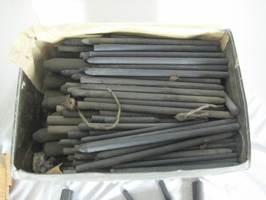
Equipment, Tin of carbon rods
... In electricity a current is conducted through carbon rod between the electrode holder and the arc in carbon arc lighting or welding. ...In electricity a current is conducted through carbon rod between the electrode holder and the arc in carbon arc lighting or welding. ...The carbon rods were either used by 'Gem Pictures' or in the study of 'Electricity and Magnetism' at the Ballarat School of Mines. In electricity a current is conducted through carbon rod between the electrode holder and the arc in carbon arc lighting or welding. A carbon rod is also used in batteries. A tin full of carbon rodsOn box found with carbon rods: "Siemens-Planiawerke aktiengesellaschaft fur kohlefabrikate berline-Lichtenberg Made in Germany jede kohle trägt unseren vollen firmenstempel Translation: Siemens Planiawerke A corporation limited by shares producing carbon in Berlin-Lichtenberg Each carbon carries our full company stampballarat school of mines, carbon, carbon rod, arc lighting, electricity, henry sutton, theatre, projector, gem pictures -
 Kiewa Valley Historical Society
Candle Holder - Wall Bracket
... Shiny metal rod with candle holder at one end and a small thin rod at the other for attaching to a device on a wall. ...This sconce was used by a resident of the Kiewa Valley. sconce candle holder wall mounted candle holder Shiny metal rod with candle holder at one end and a small thin rod at the other for attaching to a device on a wall. ...This sconce - wall mounted candle holder or light fixture is simple / basic without any decoration. It was able to swivel. It may have been used on either the interior o exterior walls of buildings. The light is usually, but not always, directed upwards and outwards, rather than down. The long bracket kept the candle a safe distance from the wall and ceiling.This sconce was used by a resident of the Kiewa Valley.Shiny metal rod with candle holder at one end and a small thin rod at the other for attaching to a device on a wall. The candle holder is surrounded by a metal shallow 'cup' with 11 oval holes enabling the wax to fall to the centre where there is a hollow globe and allowing the light to shine upwards.sconce, candle holder, wall mounted candle holder -
 Jewish Museum of Australia
Menorah, Menorah, by Mark Edgoose
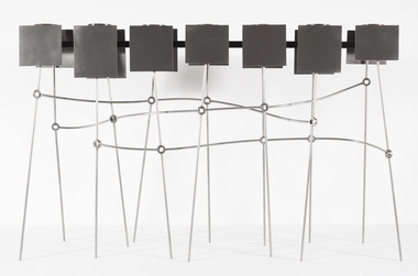
... This menorah has 7 candle holders joined in a horizontal row, on thin rod stands. The circular holders sit on two flat silver strips that are attached to silver rectangles on either side of the holders, creating a shield-like form on either side of the holder. ...Jewish Museum of Australia 26 Alma Road St Kilda melbourne This menorah has 7 candle holders joined in a horizontal row, on thin rod stands. The circular holders sit on two flat silver strips that are attached to silver rectangles on either side of the holders, creating a shield-like form on either side of the holder. ...This menorah has 7 candle holders joined in a horizontal row, on thin rod stands. The circular holders sit on two flat silver strips that are attached to silver rectangles on either side of the holders, creating a shield-like form on either side of the holder. The stand on which this construction is propped up, is made up of rods that stand vertically on either side of the holders and behind the shields. The rods are intersected by other rod 'lines' that visually weave horizontally across the top half of the stand. Each point of intersection of lines and rod stands is marked by a circular shape. Artist's statement: In terms of the Jewish diaspora, the variety and flexibility of approaches within Judaism has enabled the culture to endure and nurture ever stronger connections despite physical distance. This notion of an enriched connectedness was one of the two central ideas which contributed to the development of this piece. The second was the idea of light and its cultural significance. Light is about both practical illumination and spiritual expression. While revealing and manipulating material and form, light has also come to stand for the triumph of goodness over evil for many cultures, Of utmost importance in Jewish ritual, light and its media are also recognised symbols of connection and interaction for Jewish people throughout the world. (1999, Blessed Be the Work, Australian Contemporary Design in Jewish Ceremony II) -
 Kiewa Valley Historical Society
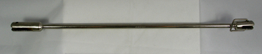
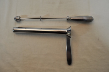
Sigmoidascope
... The part that fits inside this holder is straight with a handle at one end, with a shield to stop it travelling into its holder too far.Then it continues as a rod, half way along which is another shield until the rod stops at a solid half cylinder. ...The part that fits inside this holder is straight with a handle at one end, with a shield to stop it travelling into its holder too far.Then it continues as a rod, half way along which is another shield until the rod stops at a solid half cylinder. ...This medical / hospital instrument was used in the Tawonga District General Hospital which was built in the 1950s specifically for the increase in population due to the Kiewa Hydro Scheme.Historical: Shows the development of scientific hospital equipment. Provenance: Used in the Tawonga District General Hospital which was remote and therefore required good equipment.Used for rectal examinations. Stainless steel. 2 parts. Shaped like a gun the handle of the hollow holder being at a rectangle. The connections are attached to a cone shape. The part that fits inside this holder is straight with a handle at one end, with a shield to stop it travelling into its holder too far.Then it continues as a rod, half way along which is another shield until the rod stops at a solid half cylinder. The handle of the 'rod' is rounded with 8 faces.medical equipment. hospital equipment. sigmoidascope. rectum. mt beauty. tawonga. -
 Kiewa Valley Historical Society
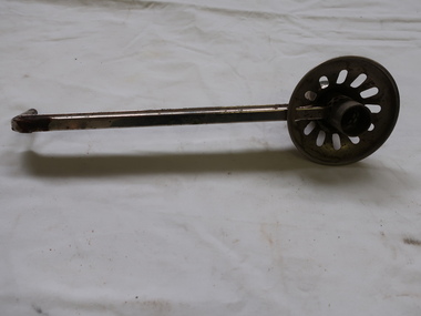
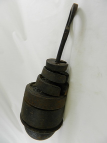
Weights - 5 in Set
... The set fit on to a holder which has a circular hook for hanging and a long straight cast iron rod going through a solid half sphere which is held with a nut at the base. ...The set fit on to a holder which has a circular hook for hanging and a long straight cast iron rod going through a solid half sphere which is held with a nut at the base. ...Used to weigh bulk produce in the Tawonga Store. Part of a platform scale.Historical: Imperial weights used before packaging of goods. Tawonga Store opened c1920 selling produce for the farming community of the Kiewa Valley.5 circular cast iron weights with a slot from the edge towards the centre. Each has a ridge around the circumference to enable each to fit on top of a bigger one. On the top, above the slot, the weight is embossed. The set is held together with a piece of wire about 50 cm long. The set fit on to a holder which has a circular hook for hanging and a long straight cast iron rod going through a solid half sphere which is held with a nut at the base. The half sphere has a wider circular base for weights to sit on. Used with scales (KVHS 0800 (B)) to weigh goods sold at Tawonga Store.Weights: 14 lbs; 28 lbs; 56 lbs; 1 cwt; 2 cwt.weights. scales. shop. store. tawonga store. -
 Bendigo Military Museum
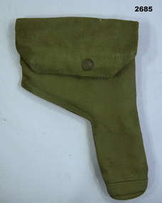
Equipment - HOLSTER, PISTOL, Post 1950
... Pistol holder, khaki coloured webbing with flap over top & press stud catch, metal clips at back to attach to belt, small cleaning rod pocket inside....Bendigo Military Museum 37 - 39 Pall Mall Bendigo goldfields mitilary equipment - firearms Passchendaele barracks trust Pistol holder, khaki coloured webbing with flap over top & press stud catch, metal clips at back to attach to belt, small cleaning rod pocket inside. ...Pistol holder, khaki coloured webbing with flap over top & press stud catch, metal clips at back to attach to belt, small cleaning rod pocket inside.mitilary equipment - firearms, passchendaele barracks trust -
 Flagstaff Hill Maritime Museum and Village
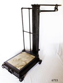
Functional object - Platform Scales
... At back, square hollow wooden post supports a hooded rod which bears the weight of the platform and which hooks onto a brass balancing arm, marked in pounds up to 50. There is a cylindrical sliding weight and on the end a loop for a metal weight holder. ...At back, square hollow wooden post supports a hooded rod which bears the weight of the platform and which hooks onto a brass balancing arm, marked in pounds up to 50. There is a cylindrical sliding weight and on the end a loop for a metal weight holder. ...Thaddeus Fairbanks (1796 –1886) was an American inventor. of heating and cook stoves, cast iron ploughs, and other items. His greatest success was the invention and manufacture of the platform scale, which allowed the weighing of large objects accurately. Fairbanks was born in Brimfield, Massachusetts, on January 17, 1796, the son of Joseph Fairbanks (1763–1846) and Phebe (Paddock) Fairbanks (1760–1853). His uncle was Ephraim Paddock, the brother of Phebe Paddock. In 1815 he moved to St. Johnsbury, Vermont, and set up a wheelwright's shop above his father's gristmill. In 1820 he married Lucy Peck Barker and In 1824 he built an iron foundry. his brother Erastus joined him to establish E. and T. Fairbanks, a partnership to manufacture heating stoves, cast iron ploughs a design for which he patented in 1826. In 1830 Fairbanks and Erastus became interested in the raising and processing of hemp. Fairbanks went on to patent a hemp and flax dressing machine and became the manager of the St. Johnsbury Hemp Company. He also built a set of scales that would measure large loads of hemp accurately, as there were no reliable scales at the time. Upon the success of building these scales, his brothers recommended that he make and sell these for general use. Fairbanks' most famous invention then became the platform scale for weighing heavy objects. These are commonly known as the Fairbanks Scales, for which he patented his original design in 1830. Before this time, accurate weighing of objects required hanging them from a balancing beam as a result, particularly heavy or ungainly objects could not be weighed accurately. A platform scale, if large enough, could weigh an entire wagon. By placing a full wagon on the scale, unloading it, and then placing it on the scale when empty, it became possible to easily and accurately calculate the weight and value of farm produce and other loads. In 1834 Fairbanks and his brother formed "E. and T. Fairbanks and Company" to manufacture and sell these platform scales. These scales were well known in the United States and around the world resulting in the company doubling in volume every three years from 1842 to 1857. There was a temporary slow down during the American Civil War, however, the business took off again after the war. Their partnership was incorporated in 1874 into a firm known as "Fairbanks Scale Company". These platform scales revolutionized weighing methods of large loads and have been in use ever since. Portable platform scales are found in almost every hardware store, physician's office, and manufacturing factory throughout the United States and the world. The first railway track platform scale patent was granted to Fairbanks on January 13, 1857, as Patent No. 16,381. In 1916 the company was purchased by ”Fairbanks, Morse and Company”. Ownership of the company has since changed several times, but Fairbanks Scales continue to be made in St. Johnsbury Vermont to this day. Fairbanks had received 43 patents in his lifetime with the last one at the age of 91. He died on April 12, 1886, and is buried at St. Johnsbury, Vermont, at the Mount Pleasant Cemetery. An early example of the first type of platform scale that revolutionised the weighing of goods throughout the world made in the USA around the turn of the 19th century. Commercially built platform scale on wheels. Cast iron base supports iron weighing platform with wooden floor. At back, square hollow wooden post supports a hooded rod which bears the weight of the platform and which hooks onto a brass balancing arm, marked in pounds up to 50. There is a cylindrical sliding weight and on the end a loop for a metal weight holder. The holder is designed for three circular pieces of metal with a slit to the centre. The weights used are 50, 100 and 200 lbs.Embossed to base Fairbanks Patent No 11 1/2, flagstaff hill, warrnambool, shipwrecked-coast, flagstaff-hill, flagstaff-hill-maritime-museum, maritime-museum, shipwreck-coast, flagstaff-hill-maritime-village, platform scales -
 Flagstaff Hill Maritime Museum and Village
Equipment - Dentist Drill, Late 19th century
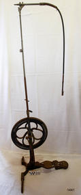
... The pulley is joined to a rod inside the arm and this spins the drill's hand-piece and dental tool holder. ...The pulley is joined to a rod inside the arm and this spins the drill's hand-piece and dental tool holder. ...The design of this and other similar treadle powered dental engine (or dentist drill) was in common use by dentists from the 1870’s into the 1920's. When electricity became accessible to most communities the electrically powered dental engines began to take over from the treadle power. Over the ages teeth were extracted using picks and scissors and other gouging instruments. Bow drills, hand drills and even a "bur thimble" drill were later used to prepare cavities for filling. Some drills were made bendable by attaching flexible shanks between the metal bur and the handle, giving access to the teeth at the back of the mouth. Other mechanical devices were introduced along the way, such as clockwork drills, but they were hard to handle and inefficient. Over the centuries “dentistry has been performed by priests, monks and other healers. This was followed by barbers; the barber’s chair may well have been the precursor to the dental chair. “(SA Medical Heritage Society Inc.) In 1871 James Morrison patented the first commercially manufactured 'foot treadle dental engine', the first practica dental engine although others had been introduced as early as 1790 (by John Greenwood). Handmade steel burs or drills were introduced for dental handpieces, taking advantage of the significant increase in the speed of the drill. In 1891 the first machine-made steel burs were in use. The treadle drill reduced the time to prepare a cavity from hours to less than ten minutes. In 1876 the Samuel S. White Catalogue of Dentist Instruments listed a 12 ½ inch wheel diameter dental engine, with 14 bright steel parts, for sale at US $55 In today’s market, this is the equivalent to US $1200 approx. The specifications of that dental engine are very similar to the this one in our Flagstaff Hill Maritime Village’s collection. It is interesting to note that workings of a similar treadle dentist drill were used and modified to power a treadle spinning wheel of one of the volunteer spinners at Flagstaff Hill Maritime Village. The foot treadle dental engine was a milestone in dental history. “Historic importance of treadle powered machines; they made use of human power in an optimal way” (Lowtech Magazine “Short history of early pedal powered machines”) The invention of a machine to speed up the process of excavation of a tooth lead to the invention of new burs and drills for the handpieces, improving speed and the surgical process of dentistry. They were the fore-runner of today’s electrically powered dental engines. This treadle-powered dentist drill, or dentist engine, is made of iron and steel and provides power for a mechanical dental hand-piece that would be fitted with a dental tool. The drill has a three footed cast iron base, one foot being longer than the other two. A vertical C shaped frame is joined into the centre of the base, holding an axle that has a driving-wheel (or flywheel) and connecting to a crank. A slender, shoulder height post, made from telescoping pipes, joins into the top of this frame and is height adjusted by a hand tightened screw with a round knob. On the post just above the frame is a short metal, horizontal bar (to hold the hand-piece when it is not in use). A narrow tubular arm is attached to the top of the stand at a right angle and can move up and down. At the end of the arm is a firmly fixed, flexible rubber hose protected for a short distance by a sheath of thin metal. At the end of the hose there is a fitting where the drill’s hand-piece would be attached; a small, silver coloured alligator clip is also at the end. A treadle, or foot pedal, is hinged to the heel to the long foot of the base, and joined at the toe to the crank that turns the driving-wheel. There is a spring under the toe of the treadle. The metal driving-wheel has a wide rim. Touching the inside of the rim are four tubular rings that bulge towards the outside of the driving-wheel, away from the pole, and all meet at the hub of the axle. The axle is bulbous between the inside of the driving-wheel and the frame then passes through the frame and is attached on the other side. The driving-wheel has a groove around which a belt would sit. The belt would also fit around a pulley on the arm, at the top of the post. The pulley is joined to a rod inside the arm and this spins the drill's hand-piece and dental tool holder. The two shorter feet of the base are made from a long metal bar that has been curved outwards, and its centre is bolted to the base of the pole. Under the ends of the curved legs of the base are wedge shaped feet. The driving-wheel is decorated in light coloured paint on both sides, each side having three sets of floral decals evenly spaced around them, and each about a sixth of the wheel's circumference. Similar decoration is along the sides of the frame. The foot pedal has decorative cutout patterns in the centre of the foot and at the toe. On the long foot of the stand is some lettering with a fine, light coloured border around it. The lettering is hard to read, being a dark colour and flaking off. There are also remnants of fine, light coloured flourishes. The foot pedal has lettering of the maker’s trade mark cast into the metal at the ball of the foot. Lettering on the base is peeling and difficult to read. The foot pedal has a trade mark cast into it that looks like a combination of ‘C’ , ‘S’ , ‘A’, ‘R’. flagstaff hill, warrnambool, shipwrecked coast, flagstaff hill maritime museum, maritime museum, shipwreck coast, flagstaff hill maritime village, great ocean road, dentist, teeth, dental drill, dental engine, treadle drill, foot powered drill, treadle engine, orthodontics, dental surgery, james morrison -
 Flagstaff Hill Maritime Museum and Village
Equipment - Dentist Drill, Late 19th century
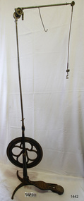
... The pulley is joined to a rod inside the arm and this spins the drill's hand-piece and dental tool holder. ...The pulley is joined to a rod inside the arm and this spins the drill's hand-piece and dental tool holder. ...The design of this and other similar treadle powered dental engine (or dentist drill) was in common use by dentists from the 1870’s into the 1920's. When electricity became accessible to most communities the electrically powered dental engines began to take over from the treadle power. Over the ages teeth were extracted using picks and scissors and other gouging instruments. Bow drills, hand drills and even a "bur thimble" drill were later used to prepare cavities for filling. Some drills were made bendable by attaching flexible shanks between the metal bur and the handle, giving access to the teeth at the back of the mouth. Other mechanical devices were introduced along the way, such as clockwork drills, but they were hard to handle and inefficient. Over the centuries “dentistry has been performed by priests, monks and other healers. This was followed by barbers; the barber’s chair may well have been the precursor to the dental chair. “(SA Medical Heritage Society Inc.) In 1871 James Morrison patented the first commercially manufactured 'foot treadle dental engine', the first practica dental engine although others had been introduced as early as 1790 (by John Greenwood). Handmade steel burs or drills were introduced for dental handpieces, taking advantage of the significant increase in the speed of the drill. In 1891 the first machine-made steel burs were in use. The treadle drill reduced the time to prepare a cavity from hours to less than ten minutes. In 1876 the Samuel S. White Catalogue of Dentist Instruments listed a 12 ½ inch wheel diameter dental engine, with 14 bright steel parts, for sale at US $55 In today’s market, this is the equivalent to US $1200 approx. The specifications of that dental engine are very similar to the this one in our Flagstaff Hill Maritime Village’s collection. It is interesting to note that workings of a similar treadle dentist drill were used and modified to power a treadle spinning wheel of one of the volunteer spinners at Flagstaff Hill Maritime Village. The foot treadle dental engine was a milestone in dental history. “Historic importance of treadle powered machines; they made use of human power in an optimal way” (Lowtech Magazine “Short history of early pedal powered machines”) The invention of a machine to speed up the process of excavation of a tooth lead to the invention of new burs and drills for the handpieces, improving speed and the surgical process of dentistry. They were the fore-runner of today’s electrically powered dental engines. This treadle-powered dentist drill, or dentist engine, is made of iron and steel and provides power for a mechanical dental handpiece that would be fitted with a dental tool. On the foot is painted lettering naming it "The Brentfield" and there is a fine line of light coloured paint creating a border around the name. The paint under the lettering is peeling off. The drill has a Y-shaped, three footed cast iron base, one foot being longer than the other two. A vertical frame is joined into the centre of the base, holding an axle that has a driving-wheel (or flywheel) and connecting to a crank. A slender, shoulder height post, made from adjustable telescoping pipes, joins into the top of this frame. On the post just above the frame is a short metal, horizontal bar (to hold the hand-piece when it is not in use). A narrow tubular arm is attached to the top of the stand at a right angle and can move up, down and around. There is a pulley each side of the joint of the arm and a short way along the arm is fitted a short metal pipe. A little further along the arm a frayed-ended cord hangs down from a hole. At the end of the arm is another pulley and a joint from which hangs a long, thin metal pipe with two pulleys and a fitting on the end. A treadle, or foot pedal, is joined to the long foot of the base, and joined at the toe to the crank that turns the driving-wheel. The metal driving-wheel has a wide rim. Touching the inside of the rim are four tubular rings that bulge towards the outside of the driving-wheel, away from the pole, and all meet at the hub of the axle. The axle fits between the inside of the driving-wheel and the frame then passes through the frame and is attached on the other side. The driving-wheel has a groove around which a belt would sit. The belt would also fit around a pulley on the arm, at the top of the post. The pulley is joined to a rod inside the arm and this spins the drill's hand-piece and dental tool holder. The foot pedal has a cross-hatch pattern on the heel and the ball of the foot has tread lines across it. The end of the toe and the instep areas have cut-out pattern in them. "The ____/ Brentfield / __ DE IN L___" (Made in London) painted on the long foot of the base. Marked on the drill connection is “Richter De Trey, Germany”flagstaff hill, warrnambool, shipwrecked coast, flagstaff hill maritime museum, maritime museum, shipwreck coast, flagstaff hill maritime village, great ocean road, dentist, teeth, dental drill, dental engine, treadle drill, foot powered drill, treadle engine, orthodontics, dental surgery, james morrison, the brentfield, richter de trey, german dental fitting, london dental drill -
 Flagstaff Hill Maritime Museum and Village
Pen holder
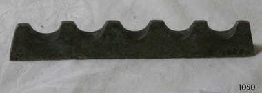
... Flagstaff Hill Maritime Museum and Village 89 Merri Street Warrnambool great-ocean-road Flagstaff Hill Warrnambool Shipwrecked-coast Flagstaff-Hill Flagstaff-Hill-Maritime-Museum Maritime-Museum Shipwreck-coast Flagstaff-Hill-Maritime-Village Metal rod of 3 flat sides and 5 half circle concave shapes across the top. Silver plated. Pen holder ...Metal rod of 3 flat sides and 5 half circle concave shapes across the top. Silver plated.flagstaff hill, warrnambool, shipwrecked-coast, flagstaff-hill, flagstaff-hill-maritime-museum, maritime-museum, shipwreck-coast, flagstaff-hill-maritime-village -
 Ballarat Tramway Museum
Document - Folder with papers, State Electricity Commission of Victoria (SECV), 1960's
... Type ‘B’ Main Cylinder 4870 6/1 7A BA-T3-6734 Brass Nut for Switch Mechanism 4829 6/2 7B BA-T3-6735 Tongue Clip Link for Switch Mechanism 4871 6/3 7C BA-T3-6736 Fulcrum for Switch Mechanism 4872 6/4 7D BA-T3-6737 Plunger for Switch Mechanism 4832 7/6 8 BA-T3-6754 Pivot for Switch Mechanism No numbers 9 or 10 4873 17/5 11 BA-T7-7639 Detail of Motor Pinion for Brill Cars 4831.2 21/4 B 12 BA-T7-7661A Half Ball Hanger Links – single bogie trucks 4874 21/6 13A BA-T7-7663 Axle Box Inner Spring Driving Wheels Maximum Traction Truck 22E 4875 22/1 13B BA-T7-7664 Axle Box Outer Spring Driving Wheels Maximum Traction Truck 22E 4876 22/2 14 BA-T7-7665 Body Spring Brill Maximum Traction Truck 22E 4830.2 22/3B 15 BA-T7-7666A Half Ball Brake Hanger Link Driving Wheel Brill Maximum Traction Truck 22E 4877 22/4 16 BA-T7-7667 Body Spring, Brush Maximum Traction Truck 22E 4820.2 22/6 A 17 BA-T7-7669 Wear cups for Half Ball Brake Hanger Links, Single & Double Bogie Trucks 4878 50/5 18 BA-T8-8149 Connections of Line Breaker and Ratchet Switch for use with Drum Controller 4879 74/6 19 BA-T13-8757/9 Signal boxes, Back of Panel Wiring and External Connections 4880 45/1 20 BA-T8-8116 Trolley Harp 4806 15/3 21 BA-T7-7625 Equalizing Lever, Fulcrum, Brill 21 E truck 4881 15/5 22 BA-T7-7626A Brake Beam Fulcrum Brill 21E truck 4808 16/1 23 BA-T7-7628 Pinion Remover, GE 201G and GE 202 motors 4882 16/3 24 BA-T7-7630 Spring Posts, Brill 21E Truck 4883 21/3 25 BA-T7-7660 Brake Shoe Holder, Driving Wheel, Maximum Traction Truck Brill 22E 4884 21/5 26 BA-T7-7662 Brake Rod Guide, Single Bogie Trucks 4885 22/5 27 BA-T7-7668 Brake Shoe Holder, Pony Wheel, Maximum Traction Truck Brill 22E 4809 42/2 B 28 BA-T8-8101 Trolley Wheel and Axle 4815 42/1 B 29 BA-T8-8102A Motor Suspension Bearing, GE 202 Motor 4796.2 42/5 30 BA-T8-8104 Connection Diagram WH 225N Motor 4886 42/6 B 31 BA-T8-8105B Motor Suspension Bearing, GE 201 Motor 4797.2 48/6 32 BA-T8-8137 WH T1F Controllers 4816 49/2 33 BA-T8-8138 Connection Diagram GE 202 Motor 4887 49/3 34 BA-T8-8139 Connection Diagram K-36-J Controller 4888 50/3 35 BA-T8-8146 GE K-36-JR Controllers, with line breaker (Connection diagram) 4889 50/6 36 BA-T8-8150 Commutator for Westinghouse 225N Motor 4846 51/1 37 BA-T8-8151A Armature Bearing Lining, Commutator End, Type GE 201G Motor 4813 51/2 38 BA-T8-8152 Armature Winding Diagram Westinghouse 225 Motor 4840.2 51/40 39 BA-T8-8154A Armature Bearing Lining, Pinion End, Type GE201G Motor 4890 51/6 40 BA-T8-8156 Armature Bearing Lining, Pinion End, Type GE202A Motor 4891 52/1 41 BA-T8-8157A Armature Bearing Lining, Commutator End, Type GE202A Motor 4892 64/5 42A BA-T9-8392A Step Hangers, Single and Double Bogie Trucks, Hinged Type 4785.2 64/6B 42B BA-T9-8392/1A Step Hangers, Single and Maximum Traction Trucks, Fixed Type 4812.2 43/1 43 BA-T8-8106B GE K36J Controller, Main Cylinder Segments 4893 50/2 44 BA-T8-8145A GE B23E Controller, Main Cylinder Segments 4816 65/2 45 BA-T9-8394B Door Lock for Motorman’ Cabin Maximum Traction Trucks. 4810 73/3 46 BA-T13-8757 Ballarat Electric Tramways Signalling System, Arrangements & Details of Box....Type ‘B’ Main Cylinder 4870 6/1 7A BA-T3-6734 Brass Nut for Switch Mechanism 4829 6/2 7B BA-T3-6735 Tongue Clip Link for Switch Mechanism 4871 6/3 7C BA-T3-6736 Fulcrum for Switch Mechanism 4872 6/4 7D BA-T3-6737 Plunger for Switch Mechanism 4832 7/6 8 BA-T3-6754 Pivot for Switch Mechanism No numbers 9 or 10 4873 17/5 11 BA-T7-7639 Detail of Motor Pinion for Brill Cars 4831.2 21/4 B 12 BA-T7-7661A Half Ball Hanger Links – single bogie trucks 4874 21/6 13A BA-T7-7663 Axle Box Inner Spring Driving Wheels Maximum Traction Truck 22E 4875 22/1 13B BA-T7-7664 Axle Box Outer Spring Driving Wheels Maximum Traction Truck 22E 4876 22/2 14 BA-T7-7665 Body Spring Brill Maximum Traction Truck 22E 4830.2 22/3B 15 BA-T7-7666A Half Ball Brake Hanger Link Driving Wheel Brill Maximum Traction Truck 22E 4877 22/4 16 BA-T7-7667 Body Spring, Brush Maximum Traction Truck 22E 4820.2 22/6 A 17 BA-T7-7669 Wear cups for Half Ball Brake Hanger Links, Single & Double Bogie Trucks 4878 50/5 18 BA-T8-8149 Connections of Line Breaker and Ratchet Switch for use with Drum Controller 4879 74/6 19 BA-T13-8757/9 Signal boxes, Back of Panel Wiring and External Connections 4880 45/1 20 BA-T8-8116 Trolley Harp 4806 15/3 21 BA-T7-7625 Equalizing Lever, Fulcrum, Brill 21 E truck 4881 15/5 22 BA-T7-7626A Brake Beam Fulcrum Brill 21E truck 4808 16/1 23 BA-T7-7628 Pinion Remover, GE 201G and GE 202 motors 4882 16/3 24 BA-T7-7630 Spring Posts, Brill 21E Truck 4883 21/3 25 BA-T7-7660 Brake Shoe Holder, Driving Wheel, Maximum Traction Truck Brill 22E 4884 21/5 26 BA-T7-7662 Brake Rod Guide, Single Bogie Trucks 4885 22/5 27 BA-T7-7668 Brake Shoe Holder, Pony Wheel, Maximum Traction Truck Brill 22E 4809 42/2 B 28 BA-T8-8101 Trolley Wheel and Axle 4815 42/1 B 29 BA-T8-8102A Motor Suspension Bearing, GE 202 Motor 4796.2 42/5 30 BA-T8-8104 Connection Diagram WH 225N Motor 4886 42/6 B 31 BA-T8-8105B Motor Suspension Bearing, GE 201 Motor 4797.2 48/6 32 BA-T8-8137 WH T1F Controllers 4816 49/2 33 BA-T8-8138 Connection Diagram GE 202 Motor 4887 49/3 34 BA-T8-8139 Connection Diagram K-36-J Controller 4888 50/3 35 BA-T8-8146 GE K-36-JR Controllers, with line breaker (Connection diagram) 4889 50/6 36 BA-T8-8150 Commutator for Westinghouse 225N Motor 4846 51/1 37 BA-T8-8151A Armature Bearing Lining, Commutator End, Type GE 201G Motor 4813 51/2 38 BA-T8-8152 Armature Winding Diagram Westinghouse 225 Motor 4840.2 51/40 39 BA-T8-8154A Armature Bearing Lining, Pinion End, Type GE201G Motor 4890 51/6 40 BA-T8-8156 Armature Bearing Lining, Pinion End, Type GE202A Motor 4891 52/1 41 BA-T8-8157A Armature Bearing Lining, Commutator End, Type GE202A Motor 4892 64/5 42A BA-T9-8392A Step Hangers, Single and Double Bogie Trucks, Hinged Type 4785.2 64/6B 42B BA-T9-8392/1A Step Hangers, Single and Maximum Traction Trucks, Fixed Type 4812.2 43/1 43 BA-T8-8106B GE K36J Controller, Main Cylinder Segments 4893 50/2 44 BA-T8-8145A GE B23E Controller, Main Cylinder Segments 4816 65/2 45 BA-T9-8394B Door Lock for Motorman’ Cabin Maximum Traction Trucks. 4810 73/3 46 BA-T13-8757 Ballarat Electric Tramways Signalling System, Arrangements & Details of Box. ...Yields information about the drawings that were used by the depot or workshop staff as reference drawings. Has a strong association with the depot workshop staff. Yields information about equipment on Ballarat tramcars and Signalling.Folder containing 46 blueprints or Dyeline prints of SEC tram equipment drawings. Front of folder made from a cloth back sheet of paper extended to secure to a thick cardboard runner. Rear of folder made from an old tram advertising panel or cardboard sheet, cut to size and secured to a thick cardboard runner with a cloth backing on both sides. Sheets secured with three brass screwed clips. Front cover damaged in bottom right hand corner. Rear cover breaking apart on outside around cloth binding. Heavy dirt marks from “grease” on bottom half of rear cover. Contains 46 drawings which have been individually catalogued and numbered on the rear of each drawing within the folder. Some of the drawings have been folded. Reg Item Micro Film No. Old BTPS No. SEC Drawing No Title 4807 42/4 1 VB4/8103C Westinghouse T1F Controller Main Cylinder Segments. 4867 47/2 2 BA-T8-8128 Westinghouse 225N Motor Case Bolt 4830 22/3 B 3 BA-T7-7666 Half Ball Brake Hanger Link, Driving Wheel, Brill Maximum Traction Truck 22E 4868 44/3A 4 BA-T8-8113 Split Suspension Bearing for Type W225 Motor (Westinghouse) 4869 52/2 5 BA-T8-8158 Contact Tips for G.E. Compressor Controller 4818 52/3 6 BA-T8-8159 GE B-23 Contact Finger Tips for G.E. Type ‘B’ Main Cylinder 4870 6/1 7A BA-T3-6734 Brass Nut for Switch Mechanism 4829 6/2 7B BA-T3-6735 Tongue Clip Link for Switch Mechanism 4871 6/3 7C BA-T3-6736 Fulcrum for Switch Mechanism 4872 6/4 7D BA-T3-6737 Plunger for Switch Mechanism 4832 7/6 8 BA-T3-6754 Pivot for Switch Mechanism No numbers 9 or 10 4873 17/5 11 BA-T7-7639 Detail of Motor Pinion for Brill Cars 4831.2 21/4 B 12 BA-T7-7661A Half Ball Hanger Links – single bogie trucks 4874 21/6 13A BA-T7-7663 Axle Box Inner Spring Driving Wheels Maximum Traction Truck 22E 4875 22/1 13B BA-T7-7664 Axle Box Outer Spring Driving Wheels Maximum Traction Truck 22E 4876 22/2 14 BA-T7-7665 Body Spring Brill Maximum Traction Truck 22E 4830.2 22/3B 15 BA-T7-7666A Half Ball Brake Hanger Link Driving Wheel Brill Maximum Traction Truck 22E 4877 22/4 16 BA-T7-7667 Body Spring, Brush Maximum Traction Truck 22E 4820.2 22/6 A 17 BA-T7-7669 Wear cups for Half Ball Brake Hanger Links, Single & Double Bogie Trucks 4878 50/5 18 BA-T8-8149 Connections of Line Breaker and Ratchet Switch for use with Drum Controller 4879 74/6 19 BA-T13-8757/9 Signal boxes, Back of Panel Wiring and External Connections 4880 45/1 20 BA-T8-8116 Trolley Harp 4806 15/3 21 BA-T7-7625 Equalizing Lever, Fulcrum, Brill 21 E truck 4881 15/5 22 BA-T7-7626A Brake Beam Fulcrum Brill 21E truck 4808 16/1 23 BA-T7-7628 Pinion Remover, GE 201G and GE 202 motors 4882 16/3 24 BA-T7-7630 Spring Posts, Brill 21E Truck 4883 21/3 25 BA-T7-7660 Brake Shoe Holder, Driving Wheel, Maximum Traction Truck Brill 22E 4884 21/5 26 BA-T7-7662 Brake Rod Guide, Single Bogie Trucks 4885 22/5 27 BA-T7-7668 Brake Shoe Holder, Pony Wheel, Maximum Traction Truck Brill 22E 4809 42/2 B 28 BA-T8-8101 Trolley Wheel and Axle 4815 42/1 B 29 BA-T8-8102A Motor Suspension Bearing, GE 202 Motor 4796.2 42/5 30 BA-T8-8104 Connection Diagram WH 225N Motor 4886 42/6 B 31 BA-T8-8105B Motor Suspension Bearing, GE 201 Motor 4797.2 48/6 32 BA-T8-8137 WH T1F Controllers 4816 49/2 33 BA-T8-8138 Connection Diagram GE 202 Motor 4887 49/3 34 BA-T8-8139 Connection Diagram K-36-J Controller 4888 50/3 35 BA-T8-8146 GE K-36-JR Controllers, with line breaker (Connection diagram) 4889 50/6 36 BA-T8-8150 Commutator for Westinghouse 225N Motor 4846 51/1 37 BA-T8-8151A Armature Bearing Lining, Commutator End, Type GE 201G Motor 4813 51/2 38 BA-T8-8152 Armature Winding Diagram Westinghouse 225 Motor 4840.2 51/40 39 BA-T8-8154A Armature Bearing Lining, Pinion End, Type GE201G Motor 4890 51/6 40 BA-T8-8156 Armature Bearing Lining, Pinion End, Type GE202A Motor 4891 52/1 41 BA-T8-8157A Armature Bearing Lining, Commutator End, Type GE202A Motor 4892 64/5 42A BA-T9-8392A Step Hangers, Single and Double Bogie Trucks, Hinged Type 4785.2 64/6B 42B BA-T9-8392/1A Step Hangers, Single and Maximum Traction Trucks, Fixed Type 4812.2 43/1 43 BA-T8-8106B GE K36J Controller, Main Cylinder Segments 4893 50/2 44 BA-T8-8145A GE B23E Controller, Main Cylinder Segments 4816 65/2 45 BA-T9-8394B Door Lock for Motorman’ Cabin Maximum Traction Trucks. 4810 73/3 46 BA-T13-8757 Ballarat Electric Tramways Signalling System, Arrangements & Details of Box.On front cover of folder, "1 - 46"trams, tramways, drawings, ballarat, sec, depot, workshops -
 Royal Australian and New Zealand College of Obstetricians & Gynaecologists (RANZCOG)
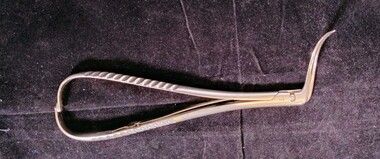
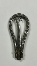
Instrument - Curved locking needle holder associated with Dr Felix Meyer, Jetter and Scheerer
... One side of the instrument is engraved with an image of the Rod of Asclepius, featuring a serpent wrapped around a staff, topped by a crown. Instrument Curved locking needle holder associated with Dr Felix Meyer Jetter and Scheerer ...Jetter and Scheerer were a surgical instrument maker founded in Germany in 1867. Their company symbol is that of a serpent curled around a rod, surmounted by a coronet/crown.This is one of a collection of items associated with Dr Felix Henry Meyer (1858-1937). Meyer was a very prominent early obstetrician and doctor, playing a part in the establishment of the role of the chair of obstetrics at the University of Melbourne in 1929. He was also a foundation member of the Royal Australian College of Surgeons.Instrument with teardrop shaped handle above two curved prongs set at an angle to the handle. Top of the handle is graduated to allow the instrument to lock in different positions, and the tension is held by a spring bar in the middle of the handle. The edges of the handle are corrugated for grip. Instrument engraved with the number '67' on inner aspect near pin, and 'PAT 5.3.92'. One side of the instrument is engraved with an image of the Rod of Asclepius, featuring a serpent wrapped around a staff, topped by a crown.'PAT 5.3.92'obstetrics, gynaecology, surgery -
 Tatura Irrigation & Wartime Camps Museum
Button hook
... Holder is an almost oval shape. Hook is in a groove and attached by a small metal rod....Holder is an almost oval shape. Hook is in a groove and attached by a small metal rod. ...Used for buttoning up shoes by the internees at camp 3Decorative metal button hook and holder. Holder is an almost oval shape. Hook is in a groove and attached by a small metal rod. -
 National Wool Museum
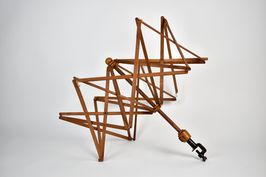
Functional object - Skein Holder, 1890-1900
... holder with a metal clamp at the base to allow it to attach to a table or similar. When not in use, item is small and compact, however once unfolded the arms extend out in an umbrella shape with thin timber rods bound together with leather ties....holder with a metal clamp at the base to allow it to attach to a table or similar. When not in use, item is small and compact, however once unfolded the arms extend out in an umbrella shape with thin timber rods bound together with leather ties. ...Skein holder is from c1890-1900 and used by four generations of the donor's family who lived around Woori Yallock and Yellingbo. Donor's family descended from settler John Douthie (1831-1897), his son Andrew Douthie married Jessie Sands Smith (1875 - 1948). Item believed to have been owned by Jessie who passed it on to her fourth child, Mary, who passed it to her child Lillian who passed it to her daughter Leanne, the donor. No makers mark on item. Mary worked as a teacher and sewing mistress at Woori Yallock Primary School and used the item in her personal time to make clothing for the family.An umbrella-style wooden skein holder with a metal clamp at the base to allow it to attach to a table or similar. When not in use, item is small and compact, however once unfolded the arms extend out in an umbrella shape with thin timber rods bound together with leather ties. -
 Tennis Australia
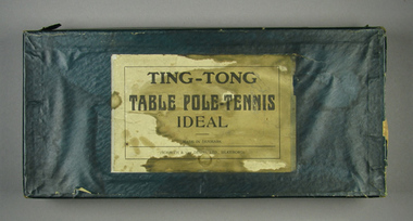
Action game, Circa 1890
... Pouch attached by string to a wood rod which is to be place in holder at centre of net. Appears complete. ...Pouch attached by string to a wood rod which is to be place in holder at centre of net. Appears complete. ...'Ting Tong Table Pole'Tennis' game. Made in Denmark. Contains two wood paddles, a wood pole and cloth tape as 'net' and two wood poles and bases to anchor net. 'Ball' is a large wooden bead held in a string pouch. Pouch attached by string to a wood rod which is to be place in holder at centre of net. Appears complete. Materials: Cardboard, Ink, Wood, Lacquer, Metal, Stringtennis -
 Melbourne Tram Museum
Drawing, Melbourne & Metropolitan Tramways Board (MMTB), "Cable Grip", Mar. 1934
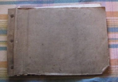
... R3485 - General Arrangement - provides a list of the parts Index - lists all the parts and relevant drawing number R3486 - Cable Grip Lever R3487 - Cable Grip Palm Handle R3488 - Cable Grip Pawl Rod Bracket and Bolt R3493 - Pawl Box, Guard Plate and Bolt R3494 - Pawl Latch Bracket R3496 - Adjusting Screw R3498 - Cable Grip Socket R3499 - Shoe and Shoe screws R3501 - Cable Grip Link R3502 - Quadrant R3503 - Crossbar R3504 - Slide and Slide end R3505 - Cheek R3506 - Protection Piece R3510 - Top Die Holder R3511 - Back Guard R3512 - Die R3513 - Bottom Die Holder R3514 - Sole Plate R3515 - Sheave R3518 - Swinger R3519 - Swinger Frame and Setscrew R3525 - Top Guide Plate R3534 - Sheave Protector R3535 - Sheave Centre R3541 - Hornbar Washer...R3485 - General Arrangement - provides a list of the parts Index - lists all the parts and relevant drawing number R3486 - Cable Grip Lever R3487 - Cable Grip Palm Handle R3488 - Cable Grip Pawl Rod Bracket and Bolt R3493 - Pawl Box, Guard Plate and Bolt R3494 - Pawl Latch Bracket R3496 - Adjusting Screw R3498 - Cable Grip Socket R3499 - Shoe and Shoe screws R3501 - Cable Grip Link R3502 - Quadrant R3503 - Crossbar R3504 - Slide and Slide end R3505 - Cheek R3506 - Protection Piece R3510 - Top Die Holder R3511 - Back Guard R3512 - Die R3513 - Bottom Die Holder R3514 - Sole Plate R3515 - Sheave R3518 - Swinger R3519 - Swinger Frame and Setscrew R3525 - Top Guide Plate R3534 - Sheave Protector R3535 - Sheave Centre R3541 - Hornbar Washer Trams tramways Cable Trams Cable Grip MMTB Lists Has Mr Pratt on front cover. ...Details the many components that went to make up a Melbourne cable tram grip. All drawings prepared by the MMTB. The second set has more components, generally bolts. See pdf files cable grip part 1, part 2 and part 3 for full details. R3485 - General Arrangement - provides a list of the parts Index - lists all the parts and relevant drawing number R3486 - Cable Grip Lever R3487 - Cable Grip Palm Handle R3488 - Cable Grip Pawl Rod Bracket and Bolt R3493 - Pawl Box, Guard Plate and Bolt R3494 - Pawl Latch Bracket R3496 - Adjusting Screw R3498 - Cable Grip Socket R3499 - Shoe and Shoe screws R3501 - Cable Grip Link R3502 - Quadrant R3503 - Crossbar R3504 - Slide and Slide end R3505 - Cheek R3506 - Protection Piece R3510 - Top Die Holder R3511 - Back Guard R3512 - Die R3513 - Bottom Die Holder R3514 - Sole Plate R3515 - Sheave R3518 - Swinger R3519 - Swinger Frame and Setscrew R3525 - Top Guide Plate R3534 - Sheave Protector R3535 - Sheave Centre R3541 - Hornbar WasherSet of 31 blueprint drawings within a brown paper folder and two brass fold back pins securing the drawings. Second copy - set of 38 drawings, black and white, loose in a sleeve. Has Mr Pratt on front cover. Date Stamped "6 Mar. 1934"trams, tramways, cable trams, cable grip, mmtb, lists