Showing 14 items matching "tail surfaces"
-
 Moorabbin Air Museum
Booklet (item) - National Advisory Committee for Aeronautics Report 688 Aerodynamic Characteristics of Horizontal Tail Surfaces, National Advisory Committee for Aeronautics Report No. 688 Aerodynamic Characteristics of Horizontal Tail Surfaces
... National Advisory Committee for Aeronautics Report 688 Aerodynamic Characteristics of Horizontal Tail Surfaces...National Advisory Committee for Aeronautics Report No. 688 Aerodynamic Characteristics of Horizontal Tail Surfaces...Moorabbin Air Museum Moorabbin Airport 12 First Street Moorabbin melbourne National Advisory Committee for Aeronautics Report No. 688 Aerodynamic Characteristics of Horizontal Tail Surfaces Booklet National Advisory Committee for Aeronautics Report 688 Aerodynamic Characteristics of Horizontal Tail Surfaces ... -
Moorabbin Air Museum
Book - Airplane stress analysis, Airplane Stress Analysis An Introductory Treatise
... ...Tail surfaces...Moorabbin Air Museum Moorabbin Airport 12 First Street Moorabbin melbourne Aircraft stress analysis Applied mechanics Beam theory Construction materials Wing analysis Chassis analysis Fuselage analysis Tail surfaces Step by step introduction to calculations required for aircraft stress analysis, circa 1929 Airplane Stress Analysis An Introductory Treatise Book Airplane stress analysis ...Step by step introduction to calculations required for aircraft stress analysis, circa 1929non-fictionStep by step introduction to calculations required for aircraft stress analysis, circa 1929applied mechanics, beam theory, construction materials, wing analysis, chassis analysis, fuselage analysis, tail surfaces -
Moorabbin Air Museum
Book - Aircraft construction, Practical Lightplane Design and Construction for the Amateur
... ...Tail surfaces...Moorabbin Air Museum Moorabbin Airport 12 First Street Moorabbin melbourne Aircraft construction Airfoils Power plants Propellers Fuel systems Landing Gear Fuselage Wings Tail surfaces Control systems Miscellaneous construction details Guidance on light aircraft construction for amateur builders, circa 1965 Practical Lightplane Design and Construction for the Amateur Book Aircraft construction ...Guidance on light aircraft construction for amateur builders, circa 1965non-fictionGuidance on light aircraft construction for amateur builders, circa 1965airfoils, power plants, propellers, fuel systems, landing gear, fuselage, wings, tail surfaces, control systems, miscellaneous construction details -
 Australian Gliding Museum
Machine - Glider – Sailplane, 1963
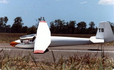
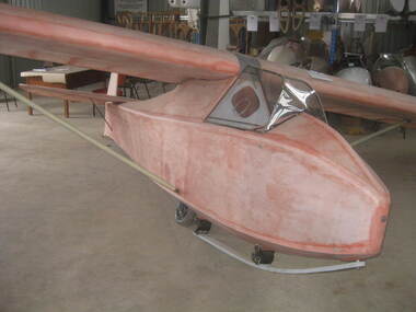
... The aircraft has a conventional arrangement for the tail stabiliser / control surfaces. ...The aircraft has a conventional arrangement for the tail stabiliser / control surfaces. Machine Glider – Sailplane Slingsby Sailplanes Ltd ...The Skylark 4, the final in the Slingsby Skylark series, dates from 1961. The design heralded a trend towards the use of plastics in the construction of gliders. Slingsby incorporated GRP (glass reinforced plastic) panels to achieve a streamlined fuselage nose and cockpit area while retaining the more traditional wood techniques for the rest of the aircraft. Another notable feature was the smooth wing surface that was obtained using a Gaboon ply skin across the ribs. Best glide performance of 1:33 was found to be comparable with the early full GRP glider designs. The Museum’s example (VH-GTB – C/N 1382) was built in 1963 and originally owned by Chuck Bentson of the UK. It was brought to Australia in 1967 by Jeremy Picket-Heaps and flown at various places including Benalla, Cooma and Gundaroo. In 1970 the glider was transferred to the New England Soaring Club. Many flights were made from Armidale and Bellata in Northern New South Wales. On one occasion, the glider was kept aloft for 8 hours 45 minutes and on another the pilot took it around a 500 kilometre triangle in nearly 8 hours. In 1980 it was sold to Ralph (“Feathers”) Crompton and was flown extensively in South Australia until 1988. The final owner before the glider was given to the Museum in 2004 was Ross Dutton of Melbourne. The last recorded flight occurred in 1992. The glider at that point had logged over 2000 hours flying time from about 2000 launches. The airframe is currently being restored to flying condition. Technically this aircraft represents the state of the art at the stage that sailplane design was changing from traditional wood construction to composites (GRP) The Slingsby Skylark 4 is high wing single seat sailplane of mainly wooden construction with plywood and fabric covering. However, the cockpit and forward part of the fuselage consists of glass reinforced plastic which was innovative at the time that the type was designed. The cockpit provides for a semi reclining position for the pilot protected with a full Perspex canopy. The wings are made up of a centre section with constant chord and tapered wing tips. The aircraft has a conventional arrangement for the tail stabiliser / control surfaces. The sailplane bears construction number 1382 and is registered in Australia as VH-GTBaustralian gliding, glider, sailplane, skylark, slingsby, bentson, picket-heaps, crompton, new england soaring club, dutton -
 Australian Gliding Museum
Machine - Glider – Sailplane, 2015
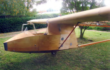
... The wings and tail / rudder surfaces have been covered with poly-fibre fabric. ...The wings and tail / rudder surfaces have been covered with poly-fibre fabric. ...The Salamandra is a Polish glider designed by Waclaw Czerwinski at the Military Glider Workshops in Krakow in 1936. This glider, designated “W.W.S.1”, was produced in substantial numbers prior to the second world war and used in Poland and some other eastern European countries for training pilots. Only one example survived the war, hidden away in the village of Goleszow in Silesia. In addition, no technical drawings could be found, so when the glider was discovered, the Gliding Institute being keen to re-establish gliding in Poland, used the glider to draw up new plans for construction. Five were built for the Institute in 1947 before production was resumed of the “Salamandra 48” at the SZD Jezow Workshops. Improvement were made by adding airbrakes and structural changes for the “Salamandra 49” and a windscreen and larger tailplane were changes adopted for the “Salamandra 53”. An export version designated “53A” was sold to and built under licence in China. Production of the Salamandra ceased in the early 1960s. Total production may have been in excess of 500. The glider was well regarded as a light weight trainer capable of soaring performance. The Museum’s replica was built by Ray Ash and may be may be classified as a “Salamandra 53”. However, he has added something of his own to the design by replacing the cable runs in the wings with control rods. The glider is substantially complete. The wings and tail / rudder surfaces have been covered with poly-fibre fabric. The fuselage woodwork is sealed with varnish. In addition to the finishing work (including painting) and rigging of the main components, the linkages for Ray’s control rod modification may need further engineering to make them operational. The Ray Ash Salamandra is the first of the type to appear in Australia. The Salamandra did not play any role in the development of gliding in Australia in the early years. However, it is an important exhibit in that it shows in tangible form a nacelle fuselage training glider in configuration and construction detail. As such it revisits the pioneering era of the 1930s and 1940s in Australia when wood, wire and fabric were the rule and the nacelle primary glider was generally the first step up for pilots who had mastered the basics in an open primary.Nacelled solo training glider of traditional wood and fabric construction. Construction incomplete.Noneaustralian gliding, sailplane, glider, salamandra, czerwinshi, poland, ash -
 Melton City Libraries
Photograph, The Cairn- Jimmy Melrose's plane crash site, 1988
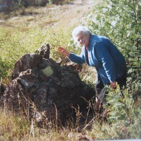
... The wing was built up of spruce box spars and lattice ribs, ply covered from the leading edge to the front spar and the fabric covered over the remainder. The tail surfaces were of similar construction. The most notable feature of the design was the lower stub wing which ran right across the fuselage embodying two box spars, plywood covered it housed the main undercarriage wheels when retracted and provided a substantial anchorage for the Nu form wing struts. ...The wing was built up of spruce box spars and lattice ribs, ply covered from the leading edge to the front spar and the fabric covered over the remainder. The tail surfaces were of similar construction. The most notable feature of the design was the lower stub wing which ran right across the fuselage embodying two box spars, plywood covered it housed the main undercarriage wheels when retracted and provided a substantial anchorage for the Nu form wing struts. ...Edna Barrie at the cairn, photo received from Graeme Minns in 1988. The cairn marks the site of Jimmy Melrose's plane crash in Melton South. The accident which happened on July 5th 1936. In 1934 Melrose made headlines with a series of spectacular flights. In July of that year, he set around Australia record and in that year established a new solo Australia England record when he flew to England to compete in the MacRoberston race with a De Havilland Puss Moth VH- YQO. The only Australian and the only solo pilot to complete the course within the time limit. He was seventh in finishing order and third in the handicap section making news again during the race with a dramatic landing in Darwin with empty fuel tanks. Late in 1935 Melrose imported the Phoenix for his “Adelaide to Anywhere” Charter Service. The previous year the Heston Aircraft Company had taken over the interests of the well known Comper Aircraft Company, and the first production of the new firm was the Phoenix, a single-engined all wooden five seater machine of sesquiplane configuration. The forward half of the fuselage was a streamlined rectangular section and the rear portion was a monocogue shell; the whole was of plywood fabric covered. The wing was built up of spruce box spars and lattice ribs, ply covered from the leading edge to the front spar and the fabric covered over the remainder. The tail surfaces were of similar construction. The most notable feature of the design was the lower stub wing which ran right across the fuselage embodying two box spars, plywood covered it housed the main undercarriage wheels when retracted and provided a substantial anchorage for the Nu form wing struts. The Dowty undercarriage retracted inwards, operated manually by hydraulic packs, Dual control fitted, with side by side seating for the pilots and three passenger seats behind. Power was a 200 h.p. De Havilland Gipsy VI 6 cylinder inverted in-line air-cooled engine. Six Phoenix were built; five of them registered in Great Britain and one of those was later sold abroad the remaining four were impressed into the R.A.F. in 1940. Specifications were: 40 feet 4 inches length 30 ft 2 ins height, 9ft 7ins, wing area 270 sq ft, Tare weight 2,600lbs loaded weight 3,300lbs; cruising speed 360 m.p.h. landing 50mph ceiling 14,000 ft range 700 miles. Melrose’s machine the first production aircraft was built early in 1936 and test flown of the 24th March. Painted green it carries the words “South Australian Centenary 1936” in silver of the fuselage and the name “Billing on the engine cowling in honor of Melrose’s uncle Noel Pemberton Billing, pioneer designer and founder of the Supermarine Aviation Company. The delivery flight was planned as a goodwill mission to publicise the forthcoming South Australian Centenary celebrations. Melrose left Dympne on the 9th April 1936, and flying via Marseilles, Naples, Athens, Baghdad, Basra, Karachi, Jodphur, Calcutta, Akyab, Penang, Singapore, Lombok, Darwin, Newcastle Waters and Alice Springs reached Adelaide on the 25th of April. Continuing the goodwill flight to other States, he visited Melbourne, Sydney, Newcastle, Grafton, Brisbane, Coff’s Harbour, Sydney again, Launceston, Hobart and Mount Gambier before returning to Adelaide on the 13th May. During June Jimmy made some charter flights and early in July was engaged by Mr. A.J. Campbell a director of several mining companies from Melbourne to Darwin to commence at Essendon on the4th July. However on that day low cloud and steady rain caused the postponement. There was little improvement and Melrose was advised to delay the departure again. However he wished to reach Oodnadatta that night, and when he observed the break in the clouds decided to leave. He planned to climb above the cloud and fly to Adelaide at 3,000 feet. The aircraft was airborne about 8.10 a.m. and was last seen from Essendon climbing above the clouds. At 8.45 people at Melton (30 miles West of Melbourne) heard an approaching aircraft. The engine noise increased abnormally and eye witnesses saw the machine fall out of control from the cloud base about 800 feet and then disintegrate, fragments were scattered for 1½ miles and both occupants were killed. Hand written carbon copy by Edna Barrie.Typed by Wendy Barrie March 2014 Last Flight of Jimmy Melrose by John Burke Parade Magazine July 1972 Page 2 –4 This article gives the take off time of 7.50 am from Essendon Airport Eyewitness account at the time Maisie Arthur’s description. Newspaper article. Edna Barrie at the site of the 'Cairn'local identities, local significant events -
 Bendigo Historical Society Inc.
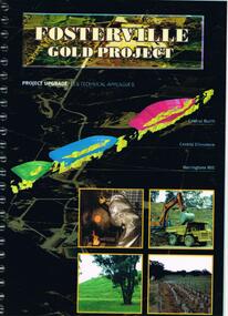
Document - FOSTERVILLE GOLD MINE COLLECTION: PROJECT UPGRADE TECHNICAL APPENDICES
... Topics: hydro geological assessment; surface drainage study, noise emission to residential properties, flora survey, tailings dam site; flora survey Wellesford Forest; Daley's Hill Plant List; diurnal Avifauna Survey - Wellesford Forest; survey of vertebrate fauna - Wellesford Forest; brief summary of fauna - Daley's Hill, Axedale, Aboriginal Archaeological survey; archaeological investigation Fosterville; traffic survey - Fosterville Sulphide Project; traffic report....History House 11 Mackenzie Street Bendigo goldfields BENDIGO Mining Fosterville Gold Mine hydro geological assessment surface drainage study noise emission to residential properties flora survey tailings dam site flora survey Wellesford Forest Daley's Hill Plant List diurnal Avifauna Survey - Wellesford Forest survey of vertebrate fauna - Wellesford Forest brief summary of fauna - Daley's Hill Axedale Aboriginal Archaeological survey archaeological investigation Fosterville traffic survey - Fosterville Sulphide Project traffic report. ...Black cover book, wire binding. Pages in reports numbered individually, overall approx 250 page report. On front: "Fosterville Gold Project' Project upgrade, EES Technical Appendix B. Central North, Central Ellesmere, Harringtons Hill." Page 1 'Perseverance Exploration Pty Limited' Book contains technical appendices. Topics: hydro geological assessment; surface drainage study, noise emission to residential properties, flora survey, tailings dam site; flora survey Wellesford Forest; Daley's Hill Plant List; diurnal Avifauna Survey - Wellesford Forest; survey of vertebrate fauna - Wellesford Forest; brief summary of fauna - Daley's Hill, Axedale, Aboriginal Archaeological survey; archaeological investigation Fosterville; traffic survey - Fosterville Sulphide Project; traffic report.bendigo, mining, fosterville gold mine, hydro geological assessment, surface drainage study, noise emission to residential properties, flora survey, tailings dam site, flora survey wellesford forest, daley's hill plant list, diurnal avifauna survey - wellesford forest, survey of vertebrate fauna - wellesford forest, brief summary of fauna - daley's hill, axedale, aboriginal archaeological survey, archaeological investigation fosterville, traffic survey - fosterville sulphide project, traffic report. -
 Australian Gliding Museum
Machine - Glider – Sailplane, 1940
... Wood and fabric single seat glider sailplane with strutted wings and strutted tailplane – features metal framed perspex canopy, central fuselage skid and wheel, small tail skid, instruments include airspeed, turn and bank indicator; variometer and altimeter. Metal parts include struts and fairing covering wing joint. All surfaces...Also the aircraft provides an insight into gliding technology in Australia in the 1940s. australian gliding glider sailplane coogee tom proctor victorian motorless flight group geelong gliding club Wood and fabric single seat glider sailplane with strutted wings and strutted tailplane – features metal framed perspex canopy, central fuselage skid and wheel, small tail skid, instruments include airspeed, turn and bank indicator; variometer and altimeter. Metal parts include struts and fairing covering wing joint. All surfaces ...The “Coogee” is an intermediate single seat sailplane designed and built by Tom Proctor in 1940. Only one was built. It was first flown at Stuart Hill near Bendigo Victoria in January 1941 and was maintained in flying condition until 1967. The aircraft was flown extensively by the Victorian Motorless Flight Group (now the Melbourne Gliding Club) and Geelong Gliding Club and several subsequent owners. This exhibit is a "one off" Australian designed and built glider similar in some respects to the Hutter H17. Its usage is relevant to the history of gliding in Victoria in the post war years. Also the aircraft provides an insight into gliding technology in Australia in the 1940s. Wood and fabric single seat glider sailplane with strutted wings and strutted tailplane – features metal framed perspex canopy, central fuselage skid and wheel, small tail skid, instruments include airspeed, turn and bank indicator; variometer and altimeter. Metal parts include struts and fairing covering wing joint. All surfaces are pink doped – awaiting painting.australian gliding, glider, sailplane, coogee, tom proctor, victorian motorless flight group, geelong gliding club -
The Ed Muirhead Physics Museum
Post Office Box (Eureka)
... tailed. Polished, coated, engraved burnished, stencil. Accessories: dials, labels, screws. Surface...tailed. Polished, coated, engraved burnished, stencil. Accessories: dials, labels, screws. Surface ...Assembled, cast hand built, moulded, dove-tailed. Polished, coated, engraved burnished, stencil. Accessories: dials, labels, screws. Surface finish: coated, polished. Inscribed on upper face along back edge: “T.E.P.L. MELBOURNE [arrow] 298 1941” Inscribed on upper face along front edge: “EUREKA BRITISH STANDARD OHMS” Labels Inscribed on upper face: “POSTIVE POLE/LINE OR EARTH” “LINE AND/GALVANOMETER” “GALVANOMETER” “NEGATIVE POLE/AT 15.5oCENT” -
The Ed Muirhead Physics Museum
Resistance Box, A.E.L
... tailed. Coated, painted. Accessories: mesh, dials. Surface finish: coated, painted. ...tailed. Coated, painted. Accessories: mesh, dials. Surface finish: coated, painted. ...Assembled, dove-tailed. Coated, painted. Accessories: mesh, dials. Surface finish: coated, painted. Inscribed on upper face, centred: “OHMS X 1000/ AUSTRONIC ENGINEERING LABORATORIES” Painted on upper face, back left corner: “PIII” -
 Wodonga & District Historical Society Inc
Album - Hume Reservoir Australia Album - Concrete pillar for tall tower, New South Wales, August 1927
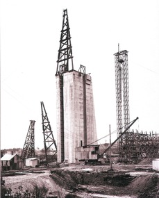
... Tail Tower of the cableway. The pillar is 108 feet from the ground and is within 4 feet of its ultimate height. The foundation of this part at its deepest is 90 feet below the natural surface so that when the 80 feet tower and jury mast are in place the total height from foundation to top of mast will be about 300 feet. ...Tail Tower of the cableway. The pillar is 108 feet from the ground and is within 4 feet of its ultimate height. The foundation of this part at its deepest is 90 feet below the natural surface so that when the 80 feet tower and jury mast are in place the total height from foundation to top of mast will be about 300 feet. ...This set of photos is from a leather bound album bearing the inscription "HUME RESERVOIR AUSTRALIA" plus 'The Rt. Hon. L. C. M. S. Amery, P. C., M .P.' all inscribed in gold. It was presented to The Rt. Hon. L. C. M. S. Amery, P. C., M. P, Secretary of State for Dominion Affairs on the occasion of his visit to the Hume Reservoir on 2nd November 1927. This album is of local and national significance as it documents the planning and development of the Hume Reservoir up to 1927. It was the largest water reservoir in the British Empire. The album records the pioneering engineering work that went into its construction.DEPARTMENT OF PUBLIC WORKS, N.S.W. RIVER MURRAY WATERS SCHEME. HUME RESERVOIR. 28. Concrete Pillar for Tail Tower. This shows the back and upstream side of the tower. The groove at the back is left for the reception of the concrete core wall of the earth embankment. The groove is being used at present as a hoist well, up and down which men and materials are conveyed in connection with the re-erection of the Tail Tower of the cableway. The pillar is 108 feet from the ground and is within 4 feet of its ultimate height. The foundation of this part at its deepest is 90 feet below the natural surface so that when the 80 feet tower and jury mast are in place the total height from foundation to top of mast will be about 300 feet. New South Wales, August 1927.hume reservoir australia, river murray waters scheme, hume reservoir construction -
 Wodonga & District Historical Society Inc
Album - Hume Reservoir Australia Album - Earth embankment on Victorian side from Top of Tail Tower Pillar, August 1927
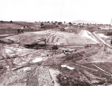
... Tail Tower Pillar - Earth Embankment, Victoria. This is a general view of the embankment which is being constructed by the Victorian Constructing Authority. The bank at its base is about 650 feet wide and it is about half its ultimate height. In the middle is the reinforced concrete core wall. At about the natural surface...Tail Tower Pillar - Earth Embankment, Victoria. This is a general view of the embankment which is being constructed by the Victorian Constructing Authority. The bank at its base is about 650 feet wide and it is about half its ultimate height. In the middle is the reinforced concrete core wall. At about the natural surface ...This set of photos is from a leather bound album bearing the inscription "HUME RESERVOIR AUSTRALIA" plus 'The Rt. Hon. L. C. M. S. Amery, P. C., M .P.' all inscribed in gold. It was presented to The Rt. Hon. L. C. M. S. Amery, P. C., M. P, Secretary of State for Dominion Affairs on the occasion of his visit to the Hume Reservoir on 2nd November 1927. This album is of local and national significance as it documents the planning and development of the Hume Reservoir up to 1927. It was the largest water reservoir in the British Empire. The album records the pioneering engineering work that went into its construction.DEPARTMENT OF PUBLIC WORKS, N.S.W. RIVER MURRAY WATERS SCHEME. HUME RESERVOIR. 31. View from Top of Tail Tower Pillar - Earth Embankment, Victoria. This is a general view of the embankment which is being constructed by the Victorian Constructing Authority. The bank at its base is about 650 feet wide and it is about half its ultimate height. In the middle is the reinforced concrete core wall. At about the natural surface a tunnel for drainage and inspection purposes is built along the downstream side of the core wall but this cannot be seen. The Victorian workshops and township are located on the high ground beyond the embankment. The embankment curves round to the left at the side of the valley and will eventually block the gulley where the bushy tree stands. Access to one of the cuttings from which material is being got for the embankment is gained by means of this gulley at present. Part of another cutting may be seen on the right hand side at the back. August 1927.hume reservoir australia, river murray waters scheme, hume reservoir construction -
 Nillumbik Shire Council
Artist Book: Tommaso DURANTE (b.1956 ITA, arrived. 2001 AUS) with text by Chris WALLACE-CRABBE (b.1934 AUS), Skin, Surfaces and Shadows, 2007
... The poet and the artist flit in and out of shadows, skin and the surfaces of paper and life. prints, artist book, skin, surface, shadow, poetry, durante, wallace-crabbe Primary Insc: In black biro, signed and editioned by Tommaso Durante and Chris Wallace-Crabbe (last page '8/25 T DURANTE CWallace-Crabbe') (a) prints, artist's book (80 pages), ink; Somerset Book White paper (175gsm), digital images, printed in eight inkjet colour pigments, from digital files. Set in digital typefaces Utopia STD Display, Italic and Bold, Frutiger 57 Condensed, 67 Bold Condensed, and 56 Italic. Section sewn around 3 tapes. Full paper binding with blind blocking on front cover handmade head and tail ...'Skin, Surfaces and Shadows' was created by Tommaso Durante in 2004 during his stay in Bundanon (gifted to the Australian people by Arthur & Yvonne Boyd - South East Australia) as international artist in residence and it was enriched during the artist’s stay in Broome (Western Australia) in 2005. On that occasion he collected the raw materials that were subsequently wrought to develop the actual bookwork.On the edge of artistic practice and philosophical inspiration, 'Skin, Surfaces and Shadows' pushes the boundaries of art, craft and design by combining digital technologies with traditional techniques and materials. Durante visually explores the surfaces of organic things (trees, surface textures, etc.) and the figurative dividing line of the shadow. The poet Wallace-Crabbe responds to these images in words. The poet and the artist flit in and out of shadows, skin and the surfaces of paper and life.(a) prints, artist's book (80 pages), ink; Somerset Book White paper (175gsm), digital images, printed in eight inkjet colour pigments, from digital files. Set in digital typefaces Utopia STD Display, Italic and Bold, Frutiger 57 Condensed, 67 Bold Condensed, and 56 Italic. Section sewn around 3 tapes. Full paper binding with blind blocking on front cover handmade head and tail bands. (b) CD of slide presentation to accompany bookwork on display Primary Insc: In black biro, signed and editioned by Tommaso Durante and Chris Wallace-Crabbe (last page '8/25 T DURANTE CWallace-Crabbe')prints, artist book, skin, surface, shadow, poetry, durante, wallace-crabbe -
 Bendigo Historical Society Inc.
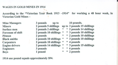
Document - Wages in gold mines 1914, 2014
... The new rates affecting Victorians were: miners, hard labor ordinary 12/- a shift; sinking 13/4; rising 14/6; underground stoping 14/-; miners, machine labor to receive 1/- per shift in addition to the above rates; timber men ordinary 13/2; shafts 16/2 a man; bracemen 12/-; truckers underground 11/6; open cut miners 13/-; laborers underground 11/-; on surface 10/-; boys between 16 and 19 9/-; over 19 full pay; shift bosses 15/-; tailings dame man 11/-; sluice man 11/-; grating man 11/-; box cleaners 11/-; pump-hole man 12/-; dressers and cleaners 13/-; man in charge erecting legs 12/6; woodcutters 12/6; woodcutter man, horse and dray 1/-/-; blacksmith 14/-; carpenter 15/-; bricklayer 15/-; tool sharpener 13/-; blacksmith's striker 11/-; rough carpenter 13/-; horse driver 11/-. ...The new rates affecting Victorians were: miners, hard labor ordinary 12/- a shift; sinking 13/4; rising 14/6; underground stoping 14/-; miners, machine labor to receive 1/- per shift in addition to the above rates; timber men ordinary 13/2; shafts 16/2 a man; bracemen 12/-; truckers underground 11/6; open cut miners 13/-; laborers underground 11/-; on surface 10/-; boys between 16 and 19 9/-; over 19 full pay; shift bosses 15/-; tailings dame man 11/-; sluice man 11/-; grating man 11/-; box cleaners 11/-; pump-hole man 12/-; dressers and cleaners 13/-; man in charge erecting legs 12/6; woodcutters 12/6; woodcutter man, horse and dray 1/-/-; blacksmith 14/-; carpenter 15/-; bricklayer 15/-; tool sharpener 13/-; blacksmith's striker 11/-; rough carpenter 13/-; horse driver 11/-. ...In April 1914, the Federated Mining Employes' Association, Victoria, put in a submission to establish improved wages for mining employees. A hearing in the Commonwealth Arbitration Court was to be held in four to six weeks from the lodgment of the plaint. The new log of claims would provide for a general increase in the previous log rates. The new rates affecting Victorians were: miners, hard labor ordinary 12/- a shift; sinking 13/4; rising 14/6; underground stoping 14/-; miners, machine labor to receive 1/- per shift in addition to the above rates; timber men ordinary 13/2; shafts 16/2 a man; bracemen 12/-; truckers underground 11/6; open cut miners 13/-; laborers underground 11/-; on surface 10/-; boys between 16 and 19 9/-; over 19 full pay; shift bosses 15/-; tailings dame man 11/-; sluice man 11/-; grating man 11/-; box cleaners 11/-; pump-hole man 12/-; dressers and cleaners 13/-; man in charge erecting legs 12/6; woodcutters 12/6; woodcutter man, horse and dray 1/-/-; blacksmith 14/-; carpenter 15/-; bricklayer 15/-; tool sharpener 13/-; blacksmith's striker 11/-; rough carpenter 13/-; horse driver 11/-. Extra rates and shorter hours for holidays and Sunday work were also demanded. (Bendigo Advertiser 27 April 1914)Printed list of mine employees' wages current in 1914. Card was used in an interpretive display to commemorate 100 years, on the 2nd of May 2014, since the devastating mine disaster at the Great Extended Hustlers Gold Mine. Seven men were killed on 2nd May 1914, in an underground explosion. The event was held on Hustler's Hill by the Bendigo Historical Society in 2014. On top of card: Wages in Gold Mines in 1914. gold mining 1914, gold mines, bendigo, employee wages, log of claims, commonwealth arbitration court, great extended hustlers gold mine