Historical information
This set of photos is from a leather bound album bearing the inscription "HUME RESERVOIR AUSTRALIA" plus 'The Rt. Hon. L. C. M. S. Amery, P. C., M .P.' all inscribed in gold. It was presented to The Rt. Hon. L. C. M. S. Amery, P. C., M. P, Secretary of State for Dominion Affairs on the occasion of his visit to the Hume Reservoir on 2nd November 1927.
Significance
This album is of local and national significance as it documents the planning and development of the Hume Reservoir up to 1927. It was the largest water reservoir in the British Empire. The album records the pioneering engineering work that went into its construction.
Physical description
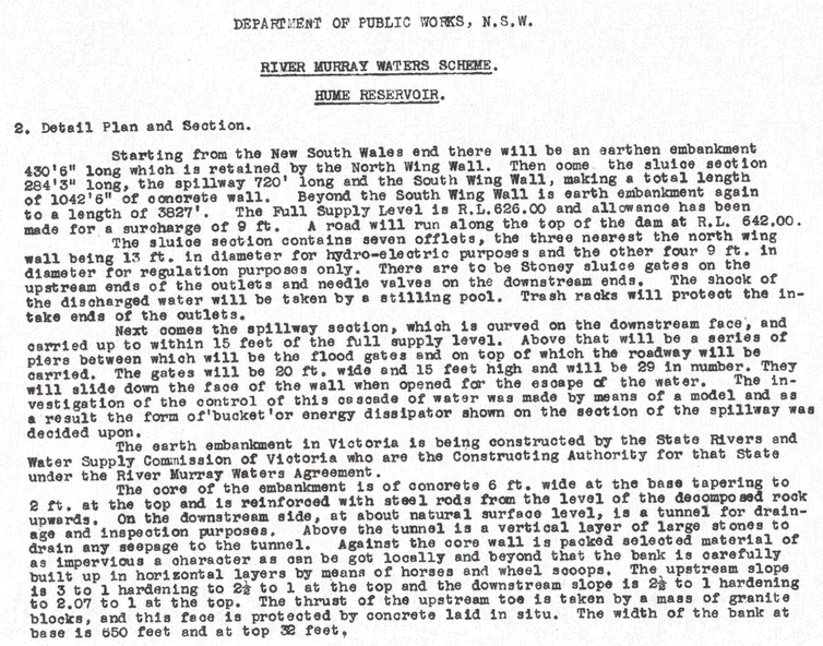
2. Detail Plan and Section.
Starting from the New South Wales and there will be an earthen embankment 430 feet 6 inches long which is retained by the North Wing Wall. Then come the sluice section 284 feet 3 inches long, the spillway 720 feet long and the South Wing Wall, making a total length of 1,042 feet 6 inches of concrete wall. Beyond the South Wing Wall is earth embankment again to a length of 3,827 feet. The Full Supply Level is R.L.626.00 and allowance has been made for a surcharge of 9 feet. A road will run along the top of the dam at R.L.642.00. The sluice section contains seven offlets, the three nearest the north wing wall being 13 feet in diameter for hydro-electric purposes and the other four 9 feet in diameter for regulation purposes only. There are to be stony sluice gates on the upstream ends of the outlets and needle valves on the downstream ends. The shock of the discharged water will be taken by a stilling pool. Trash racks will protect the intake ends of the outlets. Next comes the spillway section, which is curved on the downstream face, and carried up to within 15 feet of the full supply level. Above that will be a series of piers between which will be the flood gates and on top of which the roadway will be carried. The gates will be 20 feet wide and 15 feet high and will be 29 in number. They will slide down the face of the wall when opened for the escape of the water. The investigation of the control of this cascade of water was made by means of a model and as a result the form of “bucket” or energy dissipater shown on the section of the spillway was decided upon. The earth embankment in Victoria is being constructed by the State Rivers and Water Supply Commission of Victoria who are the Constructing Authority for that State under the River Murray Waters Agreement. The core of the embankment is of concrete 6 feet wide at the base tapering to 2 feet at the top end and is reinforced with steel rods from the level of the decomposed rock upwards. On the downstream side, at about natural surface level, is a tunnel for drainage and inspection purposes. Above the tunnel is a vertical layer of large stones to drain any seepage to the tunnel. Against the core wall is packed selected material of as impervious a character as can be got locally and beyond that the bank is carefully built up in horizontal layers by means of horses and wheel scoops. The upstream slope is 3-to-1 hardening to 2½-to-1 at the top and the downstream slope is 2½-to-1 hardening to 2.07-to-1 at the top. The thrust of the upstream toe is taken by a mass of granite blocks, and this face is protected by concrete laid in situ. The width of the bank at base is 650 feet and at top 32 feet.