Showing 96 items
matching control panel
-
 Melbourne Tram Museum
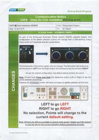
Document - Instruction, Yarra Trams, "Communications Notice EAP Z class on-tram Installation (Coming Soon)", c2014
... System. Gives position on control panels and how they operate... position on control panels and how they operate. Published ...Instruction or notice printed on A4 paper, one sided, titled "Communications Notice EAP Z class on-tram Installation (Coming Soon)", over printed for B class trams, providing information on point control system - EAP - Enhanced Automatic Points System. Gives position on control panels and how they operate. Published by Yarra Trams c2014.trams, tramways, yarra trams, points, drivers, z class, b class -
 Melbourne Tram Museum
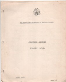
Manual, Melbourne & Metropolitan Tramways Board (MMTB), "Supervisory Equipment Operation Manual", Aug. 1963
... of the control panel, list of the substations, facilities, the control... a photograph of the control panel, list of the substations, facilities ...Manual or instruction book - 11 duplicated quarto sheets stapled on left hand edge, titled "Supervisory Equipment Operation Manual". Has the MMTB logo and name on the top of the first sheet. Describes the supervisory control system for the MMTB sub-stations and associated equipment, includes a photograph of the control panel, list of the substations, facilities, the control system, the management of the substations and the principles of operation.trams, tramways, mmtb, substation, electrical systems, electric traction, carlton -
 Federation University Historical Collection
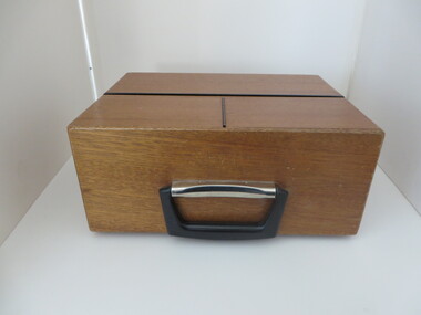
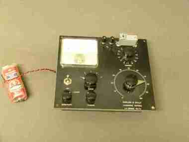
Equipment - Electrical Instrument, Moore Reed "Universal" Acoustic Coupler: Type TC301, c1980
... . The control panel is under the wooden flap. There is a power switch... to connect a telephone to dial a computer remotely. The control panel ...The Universal Acoustic Coupler was made and would have been used to connect a telephone to dial a computer remotely. The control panel is under the wooden flap. There is a power switch, full duplex switch, 500 Ma Fuse, CCITT Port. When not in use it can be folded up into a small timber carry case with handle.Wooden box with two sections that open. Top section hinged and folds back. inside are controls and cables for connecting to a computer. Instructions for use are on the lid. Front section has clips and folds down to a phone to placed in "speakers". English maker's plate and Melbourne supplier's plate with A.P.O. Permit No. C74/8/903 Serial No. 775326 moore reed, universal acoustic coupler, telephone, remote connection, computer connection -
 Federation University Historical Collection
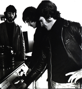
Photograph - Black and White Photograph, Students, 1977
... a control panel for equipment designed to analyse crystal structure... a control panel for equipment designed to analyse crystal structure ...Gunther Jahnke graduated in 1980. Trevor Adams graduated in 1978. Subsequently he was employed by ALCOA Australia, and by 2000 was general manager at the Portland (Vic.) plant..1) Two men, one wearing a leather jacket .2) Three men at a metallurgical apparatus .3) A handwritten note by Brian Sunter, relevant to the above photo..3) A. A group of Metallurgy students from Ballarat CAE working on equipment designed for melting metals and alloys under high vacuum conditions. (From left to right Athol Shelton, Gunther Jahnke, Trevor Adams) B. Metallurgy students operating a control panel for equipment designed to analyse crystal structure. (From left: Gunther Jahnke, Trevor Adams) alumni, brian sunter, gunther jahnke, trevor adams, athol shelton, student activity, metallurgy -
 Kiewa Valley Historical Society
Booklet - Mt Beauty and the Kiewa Scheme x2
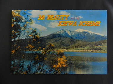
... Beauty Chalet, the Control panel at Kiewa Power Station, Clover..., the Control panel at Kiewa Power Station, Clover Dam at No. 3 Power ...This booklet was produced to advertise Mt Beauty, the Kiewa Scheme & surrounding areas to visitors / tourists. The photos cover Falls Creek with snow, lifts and skiers - one with Spion Kopje Lodge. Also Tawonga Camping ground, Bogong Village, Mt Beauty Chalet, the Control panel at Kiewa Power Station, Clover Dam at No. 3 Power Station, the road to Falls Creek and a view of Mt Beauty township. The photos indicate what Mt Beauty and the Kiewa Valley and High Plains looked like c1950's during the construction of the Kiewa Hydro Electric Scheme. The area was recognised and encouraged as a tourist attraction especially Falls Creek enabling comparison with later photos and ideas. A fold down booklet postcard size of 12 colored photos - back to back of Mt Beauty, the Kiewa Scheme & surrounds. They fold in to form a front photo with title and a back card for stamp & address of addressee. On the back of the front photo are a few paragraphs describing the beauty, history and 'things to do' in the area for the visitor / tourist. mt beauty; kiewa scheme; tawonga; bogong; clover dam; kiewa valley; bogong high plains -
 Melbourne Tram Museum
Newspaper, The Age, "Guess what he wants to be when he grows up..", 19/04/2006 12:00:00 AM
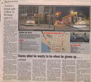
... depot, and a view of the control panel and some specifications... depot, and a view of the control panel and some specifications ...Newspaper cutting from The Age, 19/4/2005, titled "Guess what he wants to be when he grows up.." about the theft of a C class tram from Southbank depot on Sunday 17th by a youth. Gives details of the trip, passengers, the arrest and timings. Power was cut to stop the tram. Has photos of C classes at Southbank depot, and a view of the control panel and some specifications. Quotes Dennis Cliche of Yarra Trams and Senior Constable Barry Hills. Article by Dan Silkstone and Andrea Petrie.trams, tramways, theft of a tram, yarra trams, southbank depot, c class -
 Melbourne Tram Museum
Album, Gus Weir, My Melbourne Trams - Miscellaneous images, 1982 to 2011
... at Flinders St, A2 driver's control panel and Harbour Park extension.... 969 at Arts Centre, Colonial stadium, Z2 108 drivers panel ...Compiled by Gus Weir of the Wellington Tramway Museum, former Wellington tram driver. Comprises some 10 double-sided album sheets of miscellaneous photos. Includes photos of 1041, W2 512 in Seatlle, tram 969 at Arts Centre, Colonial stadium, Z2 108 drivers panel, Docklands, Domain Interchange, internal photos of C class, A2 and Z3 class, Collins St, St Vincents Plaza, Port Melbourne, Melbourne Tennis centre track under construction, signs, tram recovery vehicle, tram 1040 monument at Flinders St, A2 driver's control panel and Harbour Park extension.Yields detailed information about Melbourne trams from 1982 to 2011Set of 10 album sheets generally with four photos within a bound album, with many blanks to allow for further photos. Each photo has a label on the rear, with details of the photograph's location, photographer, and date. An insert label on each page gives the tram number, location, and date.tramways, tramcars, albums, melbourne, tram 1041, tram 512, seattle, tram 969, driver's panels, internal photos, port melbourne, docklands, st vincents plaza -
 Ballarat Tramway Museum
Document, Melbourne and Metropolitan Tramways Board (MMTB), "Tender Schedule for 100 Electric Trams Contract No. 3000", 1977
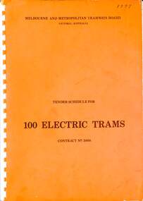
... , electrical equipment, control panels and drawings. The drawings give..., wheels, brakes, electrical equipment, control panels and drawings ...Compiled and published by the Melbourne and Metropolitan Tramways Board, closing Monday 10 May 1977. Details the conditions of tender, conditions of contract, notes, specifications, gives background information about Melbourne, dimensions, performance, drivers and conductors, trucks, wheels, brakes, electrical equipment, control panels and drawings. The drawings give a map of the system, typical city route, Glenferrie Road route (grade diagram), concrete track construction, min. radius curves, loading gauge, all-electric tram and mounting details for the trolley base, schedule of prices, tender form, form of contract, and schedule of information to be provided by the tenderer. Includes an Alphabetical Index. Includes a drawing for a single-ended version of the tramcar. Became the Z3 class following the addition of a rear or 3rd door. Yields information about the 1977 tender for 100 electric tramcars that became the Melbourne Z3 class tram.Comb bound (white plastic) specification or tender document, approx 180 pages, with glossy card orange covers, titled "Tender Schedule for Electric Trams" and "Contract 3000". "1977" on front cover in ink.tramways, tramcars, z3 class, specification, tenders, mmtb, melbourne, single ended tramcars -
 Ballarat Tramway Museum
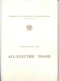
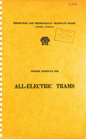
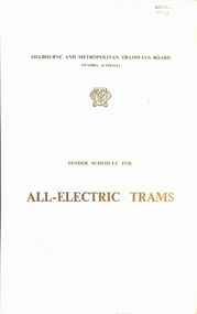
Document - Specification, Melbourne and Metropolitan Tramways Board (MMTB), "Tender Schedule for All-Electric Trams", 1972
... , electrical equipment, control panels and drawings. The drawings give..., electrical equipment, control panels and drawings. The drawings give ...Comb bound (white plastic) specification document, approx. 70 pages, with glossy card covers, titled "Tender Schedule for All-Electric Trams", published by the Melbourne and Metropolitan Tramways Board, closing 2 Oct. 1972. Details the conditions of tender, conditions of contract, notes, specification, gives background information about Melbourne, dimensions, performance, drivers and conductors, trucks, wheels, brakes, electrical equipment, control panels and drawings. The drawings give a map of the system, typical city route, Glenferrie Road route (grade diagram), concrete track construction, min. radius curves, loading gauge, all-electric tram and mounting details for the trolley base, schedule of prices, tender form, form of contract, schedule of information to be provided by the tenderer.trams, tramways, specification, tenders, z class trams, mmtb, melbourne -
 Melbourne Tram Museum
Functional object - Tramcar component, C. Brose Wuppertal Germany, Set of destination indicator equipment that was fitted to Z3 and A class trams, c1985
... to .12 .4 - set of two control panels with selection equipment... to .12 .4 - set of two control panels with selection equipment ...Set of destination indicator equipment that was fitted to Z3 and A class trams. Each item consists of various electronic parts contained within a metal case that could have been cabled together. Equipment manufactured by (Carl) C. Brose of Wuppertal Germany and maintained by Font Electronics of Melbourne - some items have the manufacturers details on them along with the details of the maintenance company and serial numbers etc. Photo .1 - shows the set of equipment as placed on display in the training room. .1 - set of two route number boxes, three individual controlled blinds, driven by a motor and control gear. Has a Fluro light fitted internally. See images .2 to .5 .2 - Small side destination indicator, with driven blind, electronic equipment with motor on the underside of the box - for use in Z class trams - see images .6 to .9 .3 - as for .2, but with motor mounted right side, used in A class trams, see images .10 to .12 .4 - set of two control panels with selection equipment for selecting the destination (by number) and route number with indicators and start button - see image .13 to 14 .5 - set of two long main rolls indicators, with control gear and Fluro light internally, driven by an internal electric motor - see images 17 and 18 .6 - set of two linking mechanism for the various boxes with large cables cut off for each of the four tram boxes. Would have been control panel item .4 - see image 15 and 16. See e-mail from Simon dated 17/11/2014. See reg Item 4617 for a small side destination roll.trams, tramways, destination indicators, a class, z3 class, transport equipment -
 Ballarat Tramway Museum
Photograph - Digital image Set of 15, Warren Doubleday and Paul Mong, 11/12 to 18/12/2004
... control panel. ... .14 - Paul working .15 - the new control panel. Photograph ...Set of 15 Digital Images of the aftermath of the sub-station repairs, wiring it up and the installation of the isolating transformer taken between 11/12/2004 and 18/12/2004 .1 - Garry Wood with some concrete for the substation floor .2 - Alan Snowball and Paul Mong laying the floor. .3 - Part of the Switchboard modified to position the new Isolating Transformer .4 - ditto .5 - the Transformer arrives - 15/12/2004 .6 - being positioned in the depot .7 - the manufacturers plate - Illawarra Transformers Wollongong .8 - unpacked .9 - being positioned .10 - In position .11 - the door to no where - the platform across to the store and archives yet to be built .12 - some of the equipment installed but found not to be suitable for the purpose. Was ex an PTC sub .13 - wiring it up .14 - Paul working .15 - the new control panel. trams, tramways, btm, substation, testing, isolating transformer -
 Melbourne Tram Museum
Photograph - Set of 14 Colour Print/s, Ray Jackson, 1979
... showing control panel .8 - Z cab being built .9 - Z class... showing control panel .8 - Z cab being built .9 - Z class ...Set of 14 colour prints of Z and Z3 trams being built and equipment at Preston Workshops and Comeng Dandenong, c1979. .1 - Two pantographs of different types laid on top of each other. .2 - ASEA trucks or bogie one marked 115 .3 - Jacobs truck or bogie for a Z3 tram .4 - Z class roof sections stored at Comeng yard .5 - Z class fronts being finished off .6 - Z or Z3 class cars bodies being built at Comeng .7 - Z cab interior showing control panel .8 - Z cab being built .9 - Z class underside or underframe .10 - Interior of Z class being built .11 - ditto .12 - as for .8 .13 - Z3 front .14 - Z class being built. Printed on Kodak Papertrams, tramways, preston workshops, z class, z3 class, pantographs, bogies, tramcar bodies, tramcar manufacture, tramcar trucks, tram 115 -
 Melbourne Tram Museum
Document - Tender Document, Melbourne & Metropolitan Tramways Board (MMTB), "Design, Manufacture and delivery of 100 only all-electric trams", Aug. 1966
... , electrical equipment, control panels and drawings. The drawings give... equipment, control panels and drawings. The drawings give a map ...Comb bound (white plastic) specification or tender document, approx. 70 pages, with glossy card covers, titled "Tender Schedule for All-Electric Trams", published by the Melbourne and Metropolitan Tramways Board, closing 12 September 1966. Details the conditions of tender, conditions of contract, notes, specification, gives background information about Melbourne, dimensions, performance, drivers and conductors, trucks, wheels, brakes, electrical equipment, control panels and drawings. The drawings give a map of the system, typical city route, Glenferrie Road route (grade diagram), concrete track construction, min. radius curves, loading gauge, all-electric tram and mounting details for the trolley base, schedule of prices, tender form, form of contract, schedule of information to be provided by the tenderer. Second copy from same donor added 9-3-2017 See Reg Item 2266 for the 1972 version and 4667 for a draft version - dated June 1965. See Item 4388 for the Z3 document. See Reg Item 4049 for associated newspaper cuttings.In red felt pen on top right hand corner "(1966)". Has stamp "Discarded from PTC Library 22 Oct. 1989" on front cover. 2nd copy has "1966" in ink in top right hand corner.trams, tramways, specification, tenders, z class, mmtb, melbourne -
 Federation University Historical Collection
Scientific Instument, Barlow & Kelly, Dip Circle Apparatus
... A.C. Bridge MK 7A. A black instrument panel with controls.... A black instrument panel with controls, connectors and a 0-5 ...A.C. Bridge MK 7A. A black instrument panel with controls, connectors and a 0-5- microAmpere DC indicator located on thetop face, and the electrical components located on the underside. No mounting frames, hence components exposed and vulnerable. scientific instrument, barlow and kelly, a.c. bridge -
 Melbourne Tram Museum
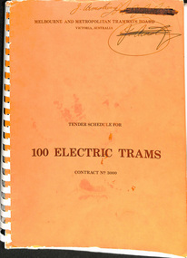
Document - Tender Document, Melbourne & Metropolitan Tramways Board (MMTB), "Tender Schedule for 100 Electric Trams Contract No. 3000", Apr. 1977
... , wheels, brakes, electrical equipment, control panels and drawings..., wheels, brakes, electrical equipment, control panels and drawings ...Comb bound (white plastic) specification or tender document, approx. 180 pages, with glossy card orange covers, titled "Tender Schedule for Electric Trams" and "Contract 3000". Compiled and published by the Melbourne and Metropolitan Tramways Board, closing Monday 10 May 1977. Details the conditions of tender, conditions of contract, notes, specification, gives background information about Melbourne, dimensions, performance, drivers and conductors, trucks, wheels, brakes, electrical equipment, control panels and drawings. The drawings give a map of the system, typical city route, Glenferrie Road route (grade diagram), concrete track construction, min. radius curves, loading gauge, all-electric tram and mounting details for the trolley base, schedule of prices, tender form, form of contract, schedule of information to be provided by the tenderer. Includes an Alphabetical Index. Includes a drawing for a single ended version of the tramcar. Became the Z3 class. Only the table of contents and the drawings scanned. See Reg Items 1583 and 2266 for other similar documents. See Reg Items 337 and 338 for a report on the operation of single ended tramcars 2 copies held.Has in ink written on front cover "J Armstrong" with a stamp blacked out and other copy of the same signature.trams, tramways, z3 class, specification, tenders, mmtb, melbourne, single ended tramcars -
 Melbourne Tram Museum
Document - Tender Document, Melbourne & Metropolitan Tramways Board (MMTB), "Tender Schedule for All-Electric Trams - Contract 2500", Jul. 1972
... , wheels, brakes, electrical equipment, control panels and drawings..., electrical equipment, control panels and drawings. The drawings give ...Comb bound (white plastic) specification or tender document, approx. 70 pages, with glossy card covers, titled "Tender Schedule for All-Electric Trams" and "Contract 2500", published by the Melbourne and Metropolitan Tramways Board, closing Monday 2 October 1972. Details the conditions of tender, conditions of contract, notes, specification, gives background information about Melbourne, dimensions, performance, drivers and conductors, trucks, wheels, brakes, electrical equipment, control panels and drawings. The drawings give a map of the system, typical city route, Glenferrie Road route (grade diagram), concrete track construction, min. radius curves, loading gauge, all-electric tram and mounting details for the trolley base, schedule of prices, tender form, form of contract, schedule of information to be provided by the tenderer. On the inside of the cover is a memo from D. Snell, Deputy Chairman to the Testing Engineer, dated 11/7/1972 about the tender being issued, but requesting least publicity and all enquiries to Mr. Snell. Part of the work to tender for the construction of Z class trams. Document scanned to pdf file word searchable. See Item 4388 for the Z3 document and 1583 for an August 1966 version and Reg item 4667 for a draft June 1965 version. 2nd copy added 7/8/2020 from Keith Kings papers.In in pencil in the top right hand corner of cover "1975" crossed out and "1972" written in. On first sheet in pencil, "Howard Smith" and "Laboratory 10 Feb 1975" stamped on.trams, tramways, specification, tenders, z class, mmtb, melbourne -
 Monash University Museum of Computing History
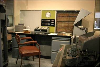
Ferranti Sirius mainframe computer, 1961
... panel and a normal clock. A moveable control panel is placed... panel and a normal clock. A moveable control panel is placed ...The Ferranti Sirius is an electronic second-generation transistor computer and is one of three remaining examples of this machine left in the world. It was an important addition to the computing facilities at Monash University in the early 1960s and provided access for computer programming and research for many early computer professionals, academics and teachers. The Ferranti Sirius computer was built in a period of rapid growth in computing technology. The first stored program computers appeared in the late 1940s and used individual designs with valve technology. By the mid-1950s valve technology was replaced by transistors and the first mass produced commercial computers became available. The Ferranti Sirius was announced in 1959 and offered a “small” academic computer. It was designed and built by the English company Ferranti Ltd and sold through a local office of the company in Melbourne. The Sirius was manufactured at the Ferranti Ltd.’s West Gorton, England factory from 1959 to 1963 and, in all, the company produced probably 22 installations although only 16 were actually recorded as sold; this included one at Ferranti’s Bureau in London and one at Ferranti’s Melbourne Bureau. Only 7 were exported and 4 of these 7 were located in Melbourne, Australia. All four were associated with computing at Monash University – the Sirius in the MMoCH collection was purchased by Monash University in 1962, a smaller Ferranti Sirius was used on the Caulfield campus (prior to amalgamation with Monash University) from 1963, the Ferranti company had its own Ferranti Sirius initially temporarily installed at Clayton campus in 1962 and then placed in their office in Queens Road, Melbourne. A fourth computer was purchased by ICIANZ (now Orica) in 1962 and was transferred to Clayton campus in 1967. Only two of these Melbourne examples have survived; one in the MMoCH collection and one at Museums Victoria. There is an example of the Ferranti Sirius in the Science Museum Group collection in the UK as well. The Ferranti Sirius in the MMoCH collection was the first computer purchased by Monash University and it was shipped to Australia to be installed by November 1962. The University had a similar model computer on loan from Ferranti Ltd during the first part of the year and it was returned to the office of the company in Queens Road, Melbourne once the University’s own machine was installed. The computer was placed on site at Clayton campus, Monash University. The computer operated from 1962 until 1972 when it was officially decommissioned. The Ferranti Sirius was sold to Mr Paul Stewart in late 1974 and removed from Monash University. Mr Stewart later donated the computer back to the University in 1988 and it was transferred to the collection of the Monash Museum of Computing History after 2001. The Ferranti Sirius is an electronic second-generation transistor computer and is one of three remaining examples of this machine left in the world. It was an important addition to the computing facilities at Monash University in the early 1960s and provided access for computer programming and research for many early computer professionals, academics and teachers. The Ferranti Sirius is of scientific (technological) significance as one of the early transistor digital computers that transitioned computing from first-generation valve computers to second generation commercial installations. This example of the Sirius is of historical significance in its role as a part of the Computer Centre, Clayton campus, Monash University which provided computing facilities in Melbourne in the early 1960s when there were few installations available for academic, administrative and commercial users. Staff and students were able to undertake investigative research and learn programming techniques. The Computer Centre encouraged the use of the computer across all disciplines and this provided the base to establish computer science as a subject offering and, later, a new department in the University. This growth in computer education eventually culminated in the establishment of the Faculty of Information Technology, Monash University. The Ferranti Sirius in the collection at Monash Museum of Computing History has a main unit with a CPU and memory combined with input/output equipment and one extra cabinet of memory. The Central Processing Unit is a floor-standing unit which contains the computer circuits, power supplies and has a decimal digit display panel and a normal clock. A moveable control panel is placed in front of the Unit (Currently set on a recreated desk/filing cabinet support in the display). The Sirius base unit uses acoustic delay line memory with 1000 word store. An additional 3000 word memory cabinet is set adjacent to the CPU and can be connected to increase the memory. The computer is supported by a range of input/output devices. There is a Ferranti Paper tape reader, located on desk in front of CPU. Red label on front “Ferranti tape reader. Type TR 5. Serial No. 477”. Adjacent to the CPU is a set of Simplified tape editing equipment in three pieces which includes a (1) Table unit with switches on front face. Metal tag on reverse reads “Creed & Co. Model No. S4060. Serial No. 1457. Original Customers Marking GRP7 V706”. The table has a numbered internal tag “Table Serial No. 198579. (2)Creed teletype set on table unit. Metal tag on reverse “Creed & Co. Model No. 75RPR K4M4. Serial No. 5897 Made in England”. (3)Creed paper tape reader set on table unit. This set of equipment could read paper tape and print it, or copy paper tape while allowing it to be edited, or allow a programmer or data preparation person to type and punch a new program or data. It has no electrical connection to the computer. Paper tapes were usually torn off and carried across to the computer. There is also another table unit with switches on front face and changeable setting switch on front right side which holds a Ferranti Westrex paper tape punch set. Label on reverse “Teletype Code BRPE11” This was the Computer’s only output device. BRPE-11 is a teletype model number. -
 Federation University Historical Collection
Object, Synchronome Co. Ltd, Synchronome Frequency Checking Master Clock No. 2191, c1930
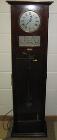
... were repeated in the operators control panel in the Power... were repeated in the operators control panel in the Power ...Information from Norman F. Dalton: Ballarat had a reticulated DC supply in the early part of last century and in 1905 had sufficient generating capacity to enable the trams to be changed from horse drawn to DC electricity. The use of electricity increased with the main power station located on Wendouree Parade, near Webster Street, under the ownership of The Electric Supply Company of Victoria. AC generating plant was installed in 1925 and conversion to AC proceeded. In 1934 the company was taken over by the State Electricity Commission Victoria (SECV) and more AC generation was installed and the changeover of customers was accelerated. This is around the time that the Synchronome Frequency Checking Mast Clock was installed at the Wendouree Parade Power Station. The SECV Annual Report of 1921 states: ::Section 11 of the act directed the COmmission to enquire into the question of securing the adoption of such standards of plant and equipment of a system, frequency and pressure for the generation and distribution of electricity as will admit of the efficient interconnection of undertakings throughout the State. In 1934 when the SECV took over the Ballarat operations the question of linking with the State grid had been a planned operation for some years but due to financial considerations had hindered it and in fact would continue to do so for a further 10 years. So while the need for close frequency control for interconnection was hardly an issue, the need to keep electric clocks correct was important, particularly as this item was a frequent sales point to cover the inconvenience and sometimes expense of converting from DC to AC. The clock is a very accurate pendulum clock with provision for varying effective length during operation for precise time regulation. There are two normal time dials and one is controlled by the pendulum and the other is operated by the system frequency. When the clock was in use it was installed by the MEter and Tests Laboratory and the time was checked daily by radio time signals. The two dials were repeated in the operators control panel in the Power Station. A maximum deviation between the two dials was set in the operating instructions (eg 5 seconds) and the operator would correct this when necessary by remote manual alteration of the turbine governor set point. The clock was used to drive and regulate a system of "slave" clocks which were used to display the time in various locations around the power station. A slave clock is a simple clock which is driven by a small electric motor, its accuracy is regulated by the master clock every 30 seconds to ensure that it and all the other slave clocks in the station are on exactly the right time; slave clocks were placed in various locations, from common rooms to workshops. A master clock could potentially run thousands of slave clocks at one plant. The clock also contains a rectifier. A rectifier is a device that is used to convert AC power to more stable DC current.Two clocks in a timber case. Both are electric, one is powered by the main pendulum mechanism, the other is a self contained electric clock. The main mechanism is of the gravity arm and roller type, which sends an impulse to the slave clocks every 30 seconds. The This Synchronome Frequency Checking Master Clock was used at the Ballarat Power Station. Below the main section of the case is a smaller cabinet containing a rectifier to provide consistent DC power for the clock. The rectifier was made by the Victorian company Hilco, which was located in Burwood. There is a high chance this is not the original rectifier from this clock as there appears to be brackets to hold a larger device in the space the rectifier occupies.Front below main clock face on front of case: "Patented Sychronome Brisbane" Lower left-hand clock face: "Frequency time" Lower right-hand clock face: "Standard Seconds" Synchronous electric clock mechanism on door (Frequency time clock): >200/250 V. 50~ >"Synchronomains" Made in England >Direction indicator for clock starting switch >"To start move lever in direction of arrow and release" >"Patent applied for" Mechanism for "standard seconds" clock: >"English Made" >"Patented" >Serial number "321" >0 above right-hand pillar on front-plate Mechanism for "standard seconds" clock: >"English Made" >"Patented" >Serial number "321" >0 above right-hand pillar on front-plate Mechanism for main clock face: >"English Made" >"Patented" >Serial number "8751" >0 above right-hand pillar on front-plate Inside case, back panel, top enamel plate: >Seconds Battery + Pos. > Battery Common or - Neg. >1/2 min dials Inside case, back panel, bottom enamel plate: external seconds dial Inside case, right hand side, electrical knobs: two switches, both "A.C. mains" Pendulum rod, below suspension spring: Serial number (?) 0000005 Rectifier in bottom cabinet: >"Hilco Rectifier" >"A.C. Volts 230/240" >"Model 1060/S" >"A.C. Amperes" >"Serial No. 1060/S >"Phases 1" >"D.C. Volts 6" >"C.P.S. 50" >"D.C. Amperes 1" >"Made in Australia by Hilco Transformers McIntyre St., Burwood, Victoria." Bakelite electrical plug: makers mark Lower cabinet, RH side panel, pressed tin plate: "AC" (upside down) Brass speed adjustment, outer right RH side: "S" and "F" Ivory and wood pendulum beat ruler: >Ruler, with 0 in centre and numbers 1-5 in ascending order from centre on left and right. > "Synchronome Patent." Steel plate, back panel, inside case, right hand side: >N R A" (descending) >"2191" serial number/part number Face of main clock: "Synchronome Electric" synchronome frequency checking master clock, electricity, state electricity commission, wendouree parade power station, secv, clock, time, pendulum, electric supply company of victoria, norman f. dalton, ballarat power station, rectifier, slave clock -
 Melbourne Tram Museum
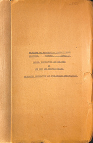
Document - Specification, Melbourne & Metropolitan Tramways Board (MMTB), "Design, Manufacture and delivery of 100 only all-electric trams", Jun. 1965
... , electrical equipment, control panels and drawings. The drawings give..., wheels, brakes, electrical equipment, control panels and drawings ...Specification or Tender Document - titled "Design, Manufacture and delivery of 100 only all-electric trams", and "Background Information and Preliminary Specification", dated June 1965. Bound into a brown foolscap card cover. Details the conditions of tender, conditions of contract, notes, specification, gives background information about Melbourne, dimensions, performance, drivers and conductors, trucks, wheels, brakes, electrical equipment, control panels and drawings. The drawings give a map of the system, typical city route, Glenferrie Road route (grade diagram), concrete track construction, min. radius curves, loading gauge, all-electric tram and mounting details for the trolley base, schedule of prices, tender form, form of contract, schedule of information to be provided by the tenderer. Comprises: 1 - Conditions of Tendering - 1 page 2 - Conditions of Contract - 4 pages 3 - Contents - 3 pages 4 - Notes for prospective tenderers - dated June 1965 5 - General nature of contract - 21 pages 6 - Appendix A - climate data - two sheets 7 - List of 14 appended drawings 8 - O.6887A - cross section of trolley wire 9 - P.13855 - Glenferrie Road, Longitudinal Section 10 - P.13856 - Wattle Park Route 11 - P.13857 - East Preston Route 12 - P13858 - Concrete track construction 13 - P13859 - Open track construction 14 - P.13860 - Paved ballast track construction 15 - P.13887 - Tram Route - locations of substations and section switches 16 - P.13888 - Minimum radius service curves to give minimum clearance between tramcars 17 - P.13889 - Grooved Rail - 102 pounds per yard and tire profile 18 - R10-301 - Loading gauge, proposed electric tramcars 19 - R9706K - Rolling stock data, tramcars 20 - R10306 - Collins Points Shifter - Wiring diagram. 21 - Schedule of data to be supplied by the tenderer 22 - notes on Automatic Points shifters - 2 sheets 23 - Tender prices and delivery periods - 2 sheets. See Reg Item 2266 for the 1972 version and 1583 for the August 1966 version. See Reg Item 4049 for associated newspaper cuttings. See file htd4667i1.pdf for scans of the drawings.In ink in top right hand corner - "Lees"trams, tramways, specification, tenders, z class, mmtb, melbourne -
 Ballarat Tramway Museum
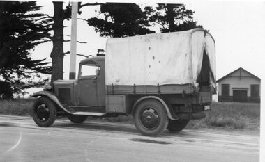
Photograph - Black & White Photograph/s, State Electricity Commission of Victoria (SECV), c1935
... view of motor generator control panel and associated cables... view of motor generator control panel and associated cables ...Set of 8 black and white photographs of the SEC Ballarat track welding truck, Reg. No. 119 341. Truck is a British Bedford truck, model WHG, built by GMH Melbourne between 1932 and 1934. Has a fabric roof, chassis fitted with a tray top body, side tool box, metal frame and covered with canvas, fitted out with a motor generator set, welding equipment and oxy acetylene bottles. Also fitted with a spot light - 'Auto Reel Lite". - See Related Items sheet on truck notes provided by Kevin Oates, MFESB workshops, 4/2001. (Scan of this sheet of the Kodak folder added 15-8-2017 - see pdf file.) 1705.1 - side on view of truck with covers down, except for opening at back. Photographed in Wendouree Parade with two different boat sheds in the background. 1705.2 - view with drivers side cover opened, showing equipment arrangement. 1705.3 - close up view of motor generator set and controls and one of the oxy acetylene bottles. 1705.4 - view showing equipment laid out on the roadway, welding cover, seat, grinder, cables, shovels, welding mask etc. 1705.5 - close up view of motor generator control panel and associated cables. 1705.6 - view of side of truck showing all equipment. 1705.7 - vertical format photo from rear of truck showing equipment laid out and wandering lead connected to the overhead. Also shows high voltage wires on a power pole fitted with a bracket arm. 1705.8 - view of truck from the front, with SEC symbol on side, with a covers closed. Thought to be photographed at loop in Wendouree Parade on the View Point line, near Mill St. Prints when donated to the BTM were contained within a red and yellow "Kodak" folder. Folder stored with catalogue worksheet. On rear of folder in ink is number "53569" and stamped on the front is number "984" and written in front top left hand cover, "8 prints" and in top right hand corner word "Sarah". See Notes provided by Kevin Oates of the MFESB (Metro Fire Brigade Melbourne) Thornbury workshops on the truck, manufacture and engine. A survey of Wendouree Parade on 22/4/2001 did not show the boat sheds or power lines featured in the photographed. Thought to be in vicinity of Power station because of the high voltage lines on the power poles.Stamped on rear in black ink, "984" on photos 1705.3 to 1705.8.trams, tramways, welding truck, trackwork, secv, wendouree parade -
 Melbourne Tram Museum
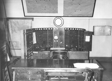
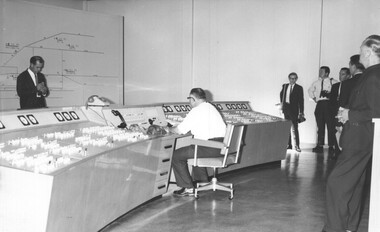
Photograph - Black & White Photograph/s, Melbourne & Metropolitan Tramways Board (MMTB), late 1964
... Black and white photographs of the Electrical Control room... of the Electrical Control room supervisory panel, that was located ...Black and white photographs of the Electrical Control room supervisory panel, that was located in Bouverie St and Queensberry St Carlton known as Carlton Control. Photograph most likely taken at the same time as the new panel was implemented - see Reg item 4514 - late 1964. Shows the panel and its set up, maps on the wall and other equipment and a table in front of the operators table or position. The MMTB News - 1721.4 - Vol. 1, No. 4 - 20 pages, November - December 1964, with a colour photo of the new Supervisory control room at Carlton on the front cover. Has articles on; chairman's message, tramway band, Carlton Control - Supervisory Centre, safe electrical working, Christmas celebrations, the old power control centre, a obituary for H. H. Bell, Remembrance day. Printed on gloss white paper.trams, tramways, carlton, substation, electrical equipment, electrical switching, carlton control -
 Melbourne Tram Museum
Photograph - Set of 5 Black & White Photograph/s, Melbourne & Metropolitan Tramways Board (MMTB), late 1964
... of the Electrical Control room supervisory panel, that was located... of the Electrical Control room supervisory panel, that was located ...Series of five black and white photographs of the Electrical Control room supervisory panel, that was located in Bouverie St and Queensberry St Carlton known as Carlton Control at the time of the implementation late 1964 .1 - General view with the Press standing around. .2 - View of the operators control desk .3 - ditto with the operator at "work" .4 - The room and map without the chair etc. .5 - ditto but a side view. The MMTB News - 1721.4 - Vol. 1, No. 4 - 20 pages, November - December 1964, with a colour photo of the new Supervisory control room at Carlton on the front cover. Has articles on; chairman's message, tramway band, Carlton Control - Supervisory Centre, safe electrical working, Christmas celebrations, the old power control centre, a obituary for H. H. Bell, Remembrance day. Printed on gloss white paper.Items .4 and .5 are stamped on the rear.trams, tramways, carlton, substation, electrical equipment, electrical switching, carlton control -
 Eltham District Historical Society Inc
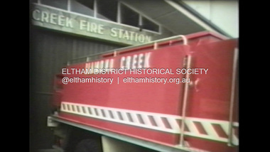
Film - Video (VHS), Diamond Creek Fire Brigade, c.1955-1987
... of the main pump and control panel on the vehicle. As well as the main... of the main pump and control panel on the vehicle. As well as the main ...Combination of three movie films. Movie One (1950s): 00:00 – 13:14 Black and white footage of Diamond Creek firemen practising in Diamond Street in the 1950s for forthcoming demonstrations of abilities. Mentions of Gordon Brandy and Joe Hislop Running out hoses from old hose reels along Diamond Street, Diamond Creek Displays from various brigades running out and connecting hoses. Also scenes from the 1950s of Diamond Creek Fire Brigade competing in various locations around Victoria and Tasmania. Mentions of Brigade members Dave Kidd, Bruce Hackett, Ron Kirkbride, Jack Marks, Graham Upton who are prominent in these events. Members of Kyneton Fire Brigade also present. Members competing in running out hose reels, connecting hoses togethers and to hydrants then climbing towers to direct water from hose or at a target hanging above the road. Diamond Creek members identified wearing a diamond on their chest and back. Includes scenes of Scottish pipe bands at the events and significant crowds of spectators. Footage of Mel Stone and Beryl Marks, Stan Redpath and Ron Kirkbride, then Ron Kirkbride and Eric Holt viewing flower displays. Film changes to colour at Diamond Creek oval for practice with fire engine entering oval. Members depicted include Bill May, Jack Sinclair, Jim Cox, Bob Beale, Dave Kidd, Bruce Hackett and Captain Clarrie Stone. Reverts to black and white in the 1950s where the Brigade joins forces with the Diamond Valley Community Hospital for a Gala Day on the Diamond Creek Oval. Changes to colour again, possibly same event and scenes of children on bikes and scooters or with prams and carts racing around the oval. Mention of young lad Brian Laurie who has his own fire truck. Dart throwing, pony rides. Scenes with Dr Don Cordner, Gus Lyons, Vic Cohn (?) and spinning wheel and Diamond Creek School children entertain a large crowd with Maypole dancing. Movie Two (1950s): 13:25 – 19:00 This black and white film was taken by a TV film crew in the 1950s depicts a typical call out for the Diamond Creek Fire Brigade. In this case the careless action of a member of the public throwing a lighted match from a car, which can cause extensive damage. Footage features the Shire of Eltham War Memorial tower at Kangaroo Ground before it was modified with a fire spotter’s cabin. Discusses fire spotting operations from the tower. Shows a fire spotter walking around the top of the tower. A fire is detected, and the information is relayed to the nearest fire station, in this case, Diamond Creek. The telephone call is received, and the alarm sounded. Captain Clarrie Stone and firemen May and Shaw leave their workplaces and prepare for action. Scenes of running across the Main Hurstbridge road showing the shops (Shell service station and Chemist prominent). Scenes entering the fire station which has a pictorial warning covering the entire door “Only you can prevent forest fires – If you’re careless – we’re homeless!” Eric Holt pinpoints the location of the fire while Captain Clarrie Stone and Fireman Shaw take note. The advance vehicle (an FE Holden ute, rego GTE-696) leaves to assess the extent of the fire. Having assessed the fire, Fireman Shaw communicates with base showing radio with call sign VL3JZ. Eric Holt takes the call. In the meantime, Captain Clarrie Stone and Fireman Shaw undertake some limited action to address the fire. Firemen Bill May, Jim Bates and Hugh Bar (?) man the tanker. A photo portrait of Queen Elizabeth is visible hanging on the wall. They are later joined by Firemen Jim Cox, Eric DeBuse (?) and Jack Marks. The tanker is seen departing the station and diverging off before the bridge. Captain Clarrie Stone and Fireman Shaw are seen pumping water on the flames with hand pumps when the tanker arrives. The hose is unreeled, and water turned on the flames. Jack Sinclair joins the action. Jim Cox directs water to the high stuff. The fire put out, Jack Marks and Eric DeBuse wind in the hoses and the team head back to town. It’s peaceful again at the memorial tower. Movie Three (1969-1987): 19:14 – 34:34 Colour film “Fired with Dedication”, Country Fire Authority Victoria, produced by I.L. Wadeson, Commentary by A.M. Hem. Credits with CFA Victoria emblem and then placed over a view of an old-style ladder engine. Opens with the scene of a fire engine outside the Diamond Creek Fire Station then various trophies reflecting the competition success of the brigade in various track and disciplined events. Two trophies shown of particular pride to the brigade were for first place in the Torchlight Procession at the State Championships in Mildura in 1986 and also at Swan Hill in 1981. Still photo scenes of ex Captain Clarrie Stone, Brigade Captain for 21 years; ex Captain Jack Marks, 10 years; ex Captain Ian Douglas, 10 years. Cuts to scene of radio control room, January 1969, and news of a fire on the northern side of the township of Diamond Creek. With scenes of flames in bush, the narration explains that until the early 1960s the area was an orchard district which protected the town against the savagery of bushfires. But due to competition from other areas more suitable for orcharding and easier transport to Melbourne the district could no longer remain competitive, and orchards were replaced by grassed areas, which together with the bush areas were a feeding ground for fire. On 8th January 1969, high temperatures and strong north winds, were, with the carelessness of some individual all that was necessary to produce the worst fire the district had seen. Cuts to scene of blackened fields and cattle - Hundreds of hectares of grass land were blackened, and cattle had to be transported to other areas for agistment. Scene of destroyed buildings in the township – 13 houses and the public hall in the town were destroyed as was the theatre equipment which was owned by the fire brigade. The Church of England Hall and bell tower were badly damaged. The whole town could have been burnt out but for the determination, skill, and courage of the Diamond Creek Fire Brigade. Scenes of all that was left of the home on the hill on the west side of the Church of England. Also, the remains of the old Pisy (?) home on the top of the same hill near Lambert Street, and the ruined Crocker home. Cuts to a scene in the mid-1970s to mid-1980s of a house fire in Haley Street attended by the Diamond Creek Fire Brigade. Although the house was severely damaged, it was saved. Mentions that whilst assistance is appreciated, in some circumstances, those doing so are not properly dressed for fighting fires. Breathing apparatus is a must in structure fire attack. Next scene (either on Mangarook or Coventry oval) showing off four Diamond Creek Fire Brigade efficient and very expensive firefighting units. Features a forward control vehicle Toyota 4WD used for conveying task force personnel to the required areas; a Hino Model 3.2 tanker, diesel powered and carries 3,000 litres of water and has a 16 HP petrol driven pump which delivers 900 litres of water per minute; an International tanker (registration TCM-418) which carries 3,000 litres of water with pumping capacity of 600 litres per minute. The Ford diesel powered pumper (registration MXE-754) is a well-equipped vehicle with a water capacity of 1,000 litres and capable of pumping 1,900 litres of water per minute from the main pump, has many lockers which hose equipment such as breathing apparatus and various types of hose nozzles and foam making equipment. The vehicle carries 360m of 64mm diameter hose which can be laid out from the rear lockers and a portable lighting plant, an Oxy Viva resuscitator to revive smoke inhalation victims and forcible entry tools to gain access to structure fires. Views of the main pump and control panel on the vehicle. As well as the main pump, the vehicle is equipped with an auxiliary pump which allows the facility to pump whilst moving. Fire fighters must undergo constant training and hone their skills, Scenes of a training exercise using the pumper to pump from static water. First, the short lengths of suction hose are coupled, a strainer fitted to ensure debris does not foul the pump. Gauges must be constantly monitored to ensure manageable water pressures are maintained. Pressures are normally controlled to allow two fire fighters to work at each nozzle outlet. Two nozzles are tested, one adjustable jet fog type which is used on flammable gasses or within a structure fire to absorb heat. A straight jet nozzle to project water long distances to protect exposed surfaces close to a fire radiated heat. The pumper is quite a versatile vehicle in handling structure fires, but it also carries specialist equipment needed in containing hazardous chemical incidents. Cuts to scene of parade – the Diamond Creek Fire Brigade has with other neighbouring brigades participated in most town fairs and earns the respect of the watching public. It can be seen why this brigade has been so successful at disciplined contests. Views of Plenty Fire Brigade Road Rescue unit which is equipped with the “Jaws of Life” Scenes of athletic competitions – many neighbouring brigades indulge in friendly but keen competition at the Diamond Creek Town Fair. The young are also encouraged to participate in all aspects of Junior Fire Brigade activities and become tomorrow’s generation of volunteer fire fighters. Scene of the 1986 Diamond Creek Town Fair which was the last time veteran Captain Clarrie Stone BEM marched with the brigade. Clarrie was awarded the British Empire Medal for his service to the Country Fire Authority. Also, scenes of vehicles in the parade. Cuts to scene of brigade members in drill formation for inspection by Acting Chief Harry Rothsay (?) on the occasion of the opening of the new fire station extensions on August 29, 1987. Rudy Libel (?) Captain at the time. Scenes of crowds including many dignitaries of neighbouring brigades present including Lieutenant Gordon Grandy (who came down from Queensland for the occasion) and ex-Secretary David Kidd and wife Betty, also ex Captain Clarrie Stone and Mrs Nel Stone, a life member of the Ladies Auxiliary, the Reverend Jock Ryan, son of J.L Ryan, founder of the Diamond Creek Fire Brigade, Foundation Captain of the fire brigade, Keith Bradbury and Mrs Bradbury. Pauline Dick accepts a community service award for services to the CFA. Recognising over 47 and a half years of service, a presentation is made by Mr Neil Marshall, Acting Chairman of the CFA to ex Captain Clarrie Stone with response by Clarrie. Other members of the official party include Cr. Martin Wright, Shire President Wayne Phillips and local Member of Parliament, Mrs Pauline Toner. Ex foreman John Bennett is presented with a life member’s awards by Captain Rudy Libel. The camera also catches Gwen Cox, Jean Ryan and Bessie Layton (?) Provides historic footage of people, places and equipment and a record of the worst fires expoerienced in Diamond Creek in 1969BASF Standard Quality SQ E-180 VHS dubbing (poor quality) of three films Converted to MP4 file format 0:34:38, 1.85GBOn label: "Donation - August 2000 Diamond Creek Unit Old films made up from Fire Brigade shows at competitions - also Kangaroo Ground Tower being used"video recording, diamond creek fire brigade, 1986 diamond creek town fair, a.m. hem, acting chief harry rothsay, athletic competitions, beryl marks, bessie layton, betty kidd, bill may, bob beale, brian laurie, bruce hackett, captain clarrie stone, chemist, church of england hall, clarrie stone, clarrie stone bem, country fire authority victoria, coventry oval, cr. martin wright, crocker home, dart throwing, dave kidd, david kidd, diamond creek, diamond creek fire station, diamond creek oval, diamond creek school, diamond creek town fair, diamond street, diamond valley community hospital, dr don cordner, eric debuse, eric holt, fe holden ute, fire damage – buildings, fire spotter, fire spotter’s cabin, fire station extension, fired with dedication (film), firefighting units, fireman shaw, firemen jim cox, ford pumper, foundation captain, gala day, gordon brandy, gordon grandy, graham upton, gus lyons, gwen cox, haley street, hino model 3.2 tanker, house fire, i.l. wadeson, ian douglas, international tanker, j.l ryan, jack marks, jack sinclair, january 1969, jaws of life, jean ryan, jim bates and hugh bar, jim cox, joe hislop, john bennett, kangaroo ground, kangaroo ground tower, keith bradbury, kyneton fire brigade, lambert street, main hurstbridge road, mangarook oval, maypole dancing, mel stone, mildura 1986, mrs bradbury, mxe754 vic registration, neil marshall, nel stone, orchard district, oxy viva resuscitator, pauline dick, pauline toner mp, pisy home, plenty fire brigade road rescue unit, pony rides, radio control room, reverend jock ryan, ron kirkbride, rudy libel, shell service station, shire of eltham war memorial, shire president wayne phillips, spinning wheel, stan redpath, state championships, swan hill 1981, tcm418 vic registration, torchlight procession, toyota 4wd, trophies, vic cohn, victorian bushfires - 1969, vl3jz -
 Bendigo Military Museum
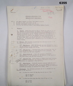
Administrative record - Royal Australian Survey Corps - Operation Sandy Bush Phase 3, Operation Instruction 8/75, 22 Sept 1975
Operation Instruction 8/75, Operation Sandy Bush Phase 3 was conducted in the period 1 Oct to 30 Nov 1975 by Det A, 8 Fd Svy Sqn. The Operation was to complete the marking, panelling measurement of already marked control in the Louisiade and D'Entrecasteaux groups and to Recce, Mark, Panel and Measure new survey control in the Trobriand and Woodlark Islands. In addition Photo Identification was to be obtained of all marked survey control. Panelling was the process of accurately laying out large sheets of white plastic to form a cross over the Survey Control Points (Points where the position is accurately known) so that they could then be photographed from the air. The positions of these crosses could then be accurately transferred from this new photography in stereo onto the aerial photography coverage used to produce mapping.Typed Instructions and diagrams without cover, 14 x A4 pages stapled in Top Left Hand Corner.Some annotations in top LH corner8 fd svy sqn, rasvy, royal australian survey corps, fortuna, army survey regiment, army svy regt -
 Eltham District Historical Society Inc
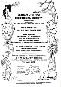
Newsletter, Newsletter, No. 128 September 1999
Contents: • Next meeting, Speaker Panel; Environmental and Conservation Groups • September Meeting • Spring Excursion – The Artists’ Trail • Acquisitions • President’s Notes • Nillumbik Planning Scheme – Heritage Planning Controls • Geoffrey Loftus-Hills • Other News Items The Shire of Eltham Historical Society was formed in October 1967. The first newsletter of the Society was issued May 1978 and has been published continuously ever since on a bi-monthly basis. With the cessation of the Shire of Eltham in late 1994, the Society's name was revised to Eltham District Historical Society and this name first appeared with issue No. 103, July 1995. The collection of the Society's newsletters provides a valuable resource on the history of the Society's activities, office bearers and committee members, guest speakers and subjects of historical interest pertinent to the former Shire of Eltham and the Eltham District.A4 photocopied newsletter distributed to membersnewsletter, eltham district historical society, shire of eltham historical society -
 Federation University Historical Collection
Instrument - equipment, Mechanical Pinwheel Calculator, c1940, 1935-1945
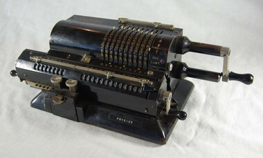
Willgodt T. Odhner invented his very successful “pinwheel” four-function calculator mechanism in Russia in 1874, and his invention was cloned by numerous companies, resulting in dozens of similar models that remained in wide use for almost a century. Numbers are dialed into the sliding levers on the top part of the machine, and are added to the register visible in the carriage at the bottom when the large crank is turned. Shifting the carriage sideways allows multiplication through a sequence of addition operations; the two small cranks zero the registers. The design includes ingenious error-preventing interlocks between all the controls: should the operator fail to return a crank to its resting position, the other controls are frozen until this is corrected. A bell indicates calculations in the negative. Used in Ballarat Institute of Advanced Education (B.I.A.E) Physics department.Black, mechanical calculating machine. Metal. Hand-operated, with three hand-cranks. 10x10 rotor with 13 digit result. Ser. No. 29-286781.5 Black symotape on base front: "PHYSICS". Maker's identification on top surface. Supplier's label (metal, silver & blue) on back: "STOTT & HOARE Pty. Ltd. 171 William St. Melbourne C1 M1991". Stamped on rear panel: "MADE IN SWEDEN". Cast lettering on underside: "M-602 07".calculating machine, pinwheel, calculator, scientific instruments, stott & hoare pty ltd, physics, odhner, ballarat institute of advanced education -
 Federation University Historical Collection
Computer, Mutlitech Industrial Corporation, Micro-Professor MPF-IP and manuals, 1983 (estimated)
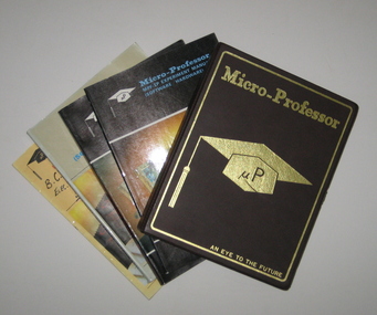
The Micro-Professor I Plus (MPF-IP) was a low cost, versatile microcomputer system featuring sophisticated software and hardware capabilities. (MPF-IP) boasted a display panel with the ability to display 20 characters using 16-segment fonts. All 64 standard ASCII characters could be displayed. The operation of the MPF-IP was controlled by an 8k monitor program which resides in the Read Only Memory (ROM). The monitor, aided by 4k Random Access Memory (RAM), enabled the user to enter a comprehensive set of single keystroke commands, making it easier for the user to use the CPU, memory and I/0 devices. This allowed the user to concentrate of microprocessor software development and application design. The system allowed printing at 48 lines per minute, and the ability to permanently record the commands, data, programs, status and other messaged. Each character printed by the printer is in a 5 by 7 dot matrix. Although the prime purpose of the programming was for machine language object code formed as hexadecimal numbers, the Micro-Professor has an embedded Tiny Basic interpreter for which formation of some of the alpha characters using a standard 7 segment display was ingenious. The program memory consisted of non volatile 2 kilobytes electrically programmable ROM whilst the Random Access Memory came with 2 kilobytes of static RAM but could be upgraded to 4 kilobytes by insertion of another chip. The entire memory space of 64 kilobytes was accessible by way of the terminals on the left hand side of the board. Engineering and Science students from the Ballarat School of Mines and the Ballarat College of Advanced Education used a class set (as they were relatively inexpensive at approx. $100 each) during the mid to late 1980s. Student were encouraged to borrow the Micro-Professors in order to assist in learning how to use them. Only one was ever not returned on time. When pressed to return the device the student confessed that his dog had chewed the plastic case. This is still in our collection complete with bite marks! The Micro-Professor used a Zilog Z80 microprocessor. This was the most powerful of the 8 bit microprocessors at the time. Zilog was derived from the Intel 8080 microprocessor. The Z80 had 158 instructions of which the Intel 78 instructions were a subset. The Intel processor continued on through development in the IBM computers as 8086, 80286, 80386, 80486 and later the pentiums. Zilog lost most of its market share when it developed the 16 bit Z8000 microprocessor. Although the microprocessor was excellent, the lack of peripherals caused users to abandon Zilog products. A brown and gold plastic box containing a microcomputer for use in classrooms. Four manuals are titled 'Micro-Professor MPF-IP user's Manual', 'MPF-I Experiment Manual (Software/Hardware)', Micro-professor MPF-IP experiment Manual (Software/Hardware)' and Micro-Professor MPF-I Monitor Program Source Listing.microcomputer, micro computer, micro professor, electronics -
 Flagstaff Hill Maritime Museum and Village
Document - Plans, Lighthouse Keeper's Quarters Warrnambool, 1858-1909
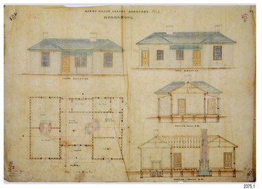
The set of seven 1858 plans shows proposed plans for the original Lighthouse Complex that was built on Middle Island in 1858-1859. The whole complex was then transferred to Flagstaff Hill in 1871. The plan, dated 1909, is for proposed additions and repairs to the Quarters at Flagstaff Hill. The plan 'Alterations and Additions' shows alternate plans for changes to the quarters at the Flagstaff Hill location. This plan has no date. The Complex comprised the Lighthouse, the Lighthouse Keepers’ Quarters, the Store (now called the Chart Room) and a Privy, which was not included in these plans. The Keeper’s bluestone Quarters was a cottage divided into two compartments, one for each keeper and his family. The bluestone Store was divided into three; a store, a workshop an oil store (or office). The Privy comprised of a small building also divided into two separate, back-to-back toilets, one for each Keeper and his family. The Flagstaff Hill Keeper's Quarters have had extensions and additions at various times, and these have also been removed at various other times. THE PLANS - *Dec. 1858 (12/58) ‘Lighthouse Keepers Quarters No.2 Warrnambool’ (2375.01)* Public Works Office Melbourne – Front and Back elevations, sections, and floor plan. The drawing shows timber walls. [The floor plan is the closest plan to the current building, however, the walls are timber in this plan.] *Nov. 1858 – No.3 ‘Lighthouse Keepers Quarters Warrnambool’ (2375.02)* Office of Public Works, Melbourne – Back and End elevations and section through. The drawing shows stone walls. One side; Senior Keeper’s bedroom, living room and kitchen with storeroom. Another side; is the Assistant’s bedroom, living room and storeroom. *Nov. 1858 - No.4 ‘Lighthouse Stores Warrnambool’ (2375.03)* Office of Public Works – Front, Side and end elevations, centre section. The drawing shows stone walls. *Nov. 1858 – No.4, ‘Lighthouse Stores No. 2 Warrnambool’ (2375.04)* Office of Public Works – Front, side and end elevations, centre section. The drawing shows timber walls. *Nov. 1858 – ‘Details Lighthouse Keepers Quarters No. 2 Warrnambool’ (2375.05)* Public Works Office Melbourne. The plan shows the foundations, joists and eaves. The drawing shows timber walls. (Nov. 1858 – ‘No.4 ‘Lighthouse No. 2 – Warrnambool’ (2375.06)* Public Works Melbourne (Part of the paper is missing). This plan shows an octagonal tower, internal stairs, a balcony landing, and a weather vane on top. *November 1858 – No. 1, ‘Lighthouse – Warrnambool’ (2375.07)* Office of Public Works Melbourne. This plan shows a round tower, including the stairs, windows on the tower and the weather vane on the top. *4/3/9 [1909] – ‘Additions and Repairs, Lighthouse Quarters, Warrnambool, General Plan’ (2375.8)* Department of Public Works Melbourne’s official stamp is signed by Croft. It shows the floor plans of the Store, Upper Lighthouse and the Quarters. The Store building has three sections; a Store, Work-Shop and Office, with an internal wall between them and separate entries. The Quarters are divided into two dwellings. The Senior Keeper’s side on the left has fireplaces in two of the three bedrooms and there is a pantry and wash house. The Assistant’s side has no fireplaces in the bedrooms and there’s no pantry or washhouse. These plans include proposed changes to the buildings. The Senior Keeper’s Quarters would have a partition on bedroom 2, a bath with plumbing and drainage, a wall moved and a built-in side porch. The Store would also have a built-in porch. The undated plan 'Additions and Alterations' (2375.9) shows alternative arrangements for water tanks, plumbing and such. WARRNAMBOOL'S LADY BAY LIGHTHOUSES- In the 1800s ships sailing from England to Australia began to use Bass Strait as a faster route to Melbourne. Small navigation errors led to many tragic shipwrecks. From 1848 lighthouses were operating along Victoria’s southern coast as a guide for sailors. Coastal towns such as Warrnambool grew and the exchange of trade and passengers were of great benefit. However, the uncertain weather changes, relatively shallow waters and treacherous, hidden rocky reefs were not suitable for a Harbour and in the 1840s and 1850s there were many shipwrecks in the area, with some even stranded in its Lady Bay harbour. A jetty was built in 1850 and a flagstaff to guide seafarers was placed up high on what became known now as Flagstaff Hill. In November 1857 the Victorian Government recommended that Warrnambool Harbour had beacons and two lighthouses to guide vessels into and out of the Harbour safely. The white light of the Middle Island lighthouse was to be used for the first time on September 1, 1859. The red light of the Beach Lighthouse, a wooden obelisk structure, was first operated on March 25, 1860, but in 1868 this light was ‘discontinued’ due to it being too low. Melbourne’s Department of Public Works decided to relocate the Middle Island Lighthouse Complex - Lighthouse, Keeper’s Quarters, Privy, Store Room and even water tanks - to Flagstaff Hill. The lower obelisk was shortened, and a protruding gallery, railing, and external ladder were added, as well as the light from the Beach Lighthouse. A green guiding light was erected on the end of the jetty. The transfer of the Complex began in March 1871. Each shaped stone of the lighthouse was carefully numbered, removed then reassembled on Flagstaff Hill. In 1872 the well was sunk behind the Lighthouse Keeper’s Cottage. The Keepers and families had left Middle Island in April and moved to Flagstaff Hill in October 1871. Vessels entering Lady Bay align the Upper and Lower Lighthouse towers during the day and the lights at night. The Upper Lighthouse is a round tower, the Lower Light is square. The Lighthouses were categorised as harbour lights rather than coastal lights, so they remain under the control of the Victorian Government’s Ports and Harbours section. The lights were originally powered by oil, then acetylene gas, later by electricity, and then converted to solar power in 1988. In 1993 the solar panel was replaced by a battery charger. A decision was made in 1936 to replace the lighthouses’ lights with unattended lights that no longer required Keepers and Assistants. At least 29 Keepers had attended to the lighthouse from its opening in 1859 to when the last official Lightkeepers left In April 1916. The Warrnambool Harbour Board rented out the Quarters from 1916 to 1936. The Board closed down but the rentals continued with other unknown landlords. In the 1970s the Flagstaff Hill Planning Board was set up under the chairmanship of John Lindsay. The Board was to make recommendations to the Warrnambool City Council regarding the use of the buildings and the rest of the Crown Land on the site. The Flagstaff Hill Maritime Village opened in 1975 and began renovating the Cottage in stages, during which time evidence of a 1920s fire was found in the eastern section of the cottage. Additions of a porch on the west and a washroom on the east were made in the 1980s. The western part of the building is now a Shipwreck Museum and the east has returned to a late 19th-century Lighthouse Keeper’s cottage and includes the screen made by Assistant Lighthouse Keeper Thomas Hope during one of his two periods of service there. THE LIGHTHOUSE KEEPERS Lighthouse Keepers were responsible for keeping their Lighthouse’s lights shining at night. They kept a lookout for passing vessels and changes in weather. They were expected to clean, polish and maintain the equipment and buildings. They kept regular and detailed records of who was on watch, and the time the light was lit, trimmed and extinguished. They kept a journal about other events that occurred. They keep regular, accurate Meteorological Logs. It was expected that they were competent in Morse code signalling. They would be called to help in times of disasters and shipwrecks, and to give official statements about these events. Many Lighthouse Keepers also volunteered as members of the lifeboat crew. The Lady Bay lighthouses were officially classified as small, so the Keepers had the official titles of Senior Assistant Lighthouse Keeper and Assistant Lighthouse Keeper. They were employed by the Public Service and paid rent to live in the Lighthouse Quarters. They were compulsorily retired at the age of 60, with most receiving a superannuation payment. Despite their time-consuming duties, there was time to follow hobbies and crafts such as growing vegetables, playing musical instruments, making models of buildings including lighthouses, and crafting furniture pieces. An example of a keeper’s skills is the carved fire screen made by /assistant Keeper Thomas Hope in the early 20th century and displayed in the Lighthouse Keeper’s cottage at Flagstaff Hill. The last occupants of the Middle Island Complex were Senior Keeper Robert Deverell, his Assistant Keeper, Andrew Farncombe, and their families. They all became the first occupants at the Lady Bay Lighthouse Keepers’ Quarters on Merri Street. The Warrnambool Lighthouse Complex plans are the origin of what is now the Lady Bay Lighthouse Complex. They are a record of the people, process and departments involved in bringing the complex into fruition. The plans are significant to the Complex, which is now listed on the Victorian Heritage Register, H1520, for being of historical, scientific (technological) and architectural significance to the State of Victoria. The Complex is significant as an example of early colonial development. The plan are significant for their connection with the important navigational function of the Lighthouses, a function still being performed to this day. The plans are also significant as an example of a product from the Public Works Department in Victoria in the mid-to-late 19th century. The structures built to these plans still stand strong. Plans for the Lighthouse Complex in Warrnambool, including Lighthouses, Keeper's Quarters and Stores. Seven of the plans are on thin fragile paper, one is on thicker, stronger paper. The drawings have been made in pens coloured red and black. They originate from Public Works in Melbourne. Seven were drawn in 1858, one in 1904, the other is not dated.Dec. 1858 - Lighthouse Keepers Quarters No.2 Warrnambool. Public Works Office Melbourne. Nov. 1858 - No.3 ‘Lighthouse Keepers Quarters Warrnambool. Public Works Office Melbourne. Nov. 1858 - No.4 ‘Lighthouse Stores Warrnambool. Office of Public Works. Nov. 1858 - No.4, ‘Lighthouse Stores No. 2 Warrnambool. Office of Public Works. Nov. 1858 - Details Lighthouse Keepers Quarters No. 2 Warrnambool. Public Works Office Melbourne. Nov. 1858 - No.4 ‘Lighthouse No. 2 – Warrnambool. Public Works Melbourne. Nov. 1858 - No. 1, Lighthouse - Warrnambool. Office of Public Works Melbourne. 4/3/9 [1909] - Additions and Repairs, Lighthouse Quarters, Warrnambool, General Plan. Department of Public Works Melbourne. SIGNED "Croft" "15A" on reverse [no date] - Lighthouse Quarters Warrnambool, Additions and Alterations. "9A" on reverseflagstaff hill, warrnambool, lighthouse keeper's cottage, lighthouse residence, lighthouse, plans, public works, melbourne, flagstaff hill maritime museum, maritime museum, shipwreck coast, flagstaff hill maritime village, chart room, quarters, privy, middle island, beach lighthouse, obelisk, lighthouse keeper, assistant keeper, lighthouse complex, lady bay, lady bay complex, keepers, upper lighthouse, lower lighthouse, ports and harbours, cottage, harbour board, flagstaff hill planning board, meteorological record, robert deverell, andrew farncombe, warrnambool port, warrnambool harbour, residence, alterations, repairs, department of works -
 National Vietnam Veterans Museum (NVVM)
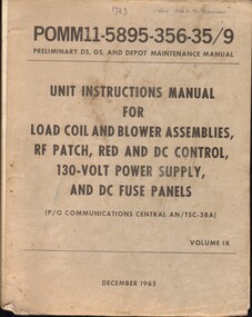
Manual, Collins Radio Co, Unit instructions Manual For Load Coil and Blower assemblies, RF Patch, Red and DC Control, 130-Volt Power Supply, and DC Fuse Panels (P/O Commumications Centra; AN/TSC-38A) Volume IX, 1965
A cream coloured manual with black writing on the cover. There is written in blue ink 18615 2Lt L.B. Dawsonelectronic manuals, communications, military radios -
Port Melbourne Historical & Preservation Society
Document - Reports, Department of Infrastructure, C5 amendment to Port Phillip Planning Scheme, Department of Infrastructure, 1999
The C5 Amendment aimed to create a framework for built form and development controls in the Port Melbourne Mixed Use Area undergoing conversion to residential development. Heritage overlays to protect heritage areas were also under review.Developer submissions to an independent Panel reviewing the C5 amendment to the Port Phillip Planning Scheme, 1999 Report from Department of Infrastructuretown planning, built environment - civic, heritage, becton, fox hay timber and hardware pty ltd