Showing 87 items
matching distance measures
-
 Moorabbin Air Museum
Manual (item) - Nomad Distance Measuring System ?Maintenance Manual
... Moorabbin melbourne Nomad Distance Measuring System ?Maintenance ... -
Tatura Irrigation & Wartime Camps Museum
Photograph, Cattanach Canal, 1957
Taken by the photographer for Victoria State Rivers and Water Supply Commission.Large sepia photograph - large stretch of water in foreground, men leaning down from platform above measuring weir in middle of photograph - trees on bank left and middle distance.Above photo: "Cattanach Canal / Inlet and Measuring Weir to Waranga Basin."irrigation, victoria state rivers and water supply commission, cattanach canal, waranga basin, measuring weir -
Creswick Campus Historical Collection - University of Melbourne
Equipment, Ranging 120
... Black case with lens and scale. For measuring 2 - 30m.... For measuring 2 - 30m distance, height, width. In original cardboard box ...Black case with lens and scale. For measuring 2 - 30m distance, height, width. In original cardboard box.Equipment -
 Dandenong/Cranbourne RSL Sub Branch
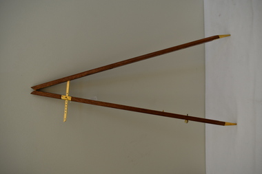
Instrument - Pace Stick
The Pace Stick is used to measure the correct length of pace. Rhythm and uniformity in marching is achieved by using the Pace Stick as well as the drum and metronome. Correct pace length is necessary not only for ceremonial purposes, but also to reduce fatigue on long marches and set the standard of accuracy required of soldiers. The Pace Stick is actually two pieces of timber, hinged at the top and able to be set to a particular distance, something like the compass set you used at school. -
Moorabbin Air Museum
Manual (Item) - Mark 5 Airborne distance measuring equipment, ARINC characteristic 709, 710, 711, 712, 713, 714, 715, 716, 717
... , 714, 715, 716, 717 Manual Mark 5 Airborne distance measuring ... -
Moorabbin Air Museum
Manual (Item) - RTCA - Minimum performance standards airborne distance measuring equipment (DME) operating within radio frequency range of 960-1215 megahertz, RTCA Document DO-151A
... performance standards airborne distance measuring equipment (DME ... -
Moorabbin Air Museum
Manual (Item) - King Instruction Manual KN-60 Distance Measuring Equipment
... Moorabbin melbourne King Instruction Manual KN-60 Distance Measuring ... -
Moorabbin Air Museum
Manual (Item) - Bendix/King Distance Measuring Equipment Installation Manual, KN 63 Distance Measuring Equipment Installation Manual
... Distance Measuring Equipment Installation Manual Manual Bendix/King ... -
Moorabbin Air Museum
Manual (Item) - King DIstance Measuring Equipment Maintenance/Overhaul Manual, Maintenance/Overhaul Manual KDM 705A Distance Measuring Equipment
... Maintenance/Overhaul Manual KDM 705A Distance Measuring Equipment ... -
Moorabbin Air Museum
Manual (Item) - King Distance Measuring Equipment Installation Manual, KN 62/62A/64 Distance Measuring Equipment Installation Manual
... /62A/64 Distance Measuring Equipment Installation Manual Manual ... -
Moorabbin Air Museum
Manual (Item) - Bendix/King Distance Measuring Equipment Installation Manual, Installation Manual KDM 706/706A Distance Measuring Equipment
... Installation Manual KDM 706/706A Distance Measuring Equipment Manual ... -
Moorabbin Air Museum
Document (Item) - includes, DME, distance measuring equipment, Nomad, Qantas 747, DC9, microwave, Ikara, Jindivik, fire rescue vehicles, Airtruk, Australian aerospace
... , distance measuring equipment, Nomad, Qantas 747, DC9, microwave ... -
Moorabbin Air Museum
Manual (Item) - KDM 7000B Distance Measuring Equipment System Bendix/King General Avionics Division
... Manual KDM 7000B Distance Measuring Equipment System Bendix/King ...Manual Number 006-00155-0003 -
 Queenscliffe Maritime Museum
Tool - Navigation, ship's Log, 25 May 2011
A Ship's Log looked very similar to a torpedo but was used to measure the speed of a ship. When dragged behind the vessel, movement of water past the propeller caused it to rotate, turning the small needle dials to record the distance and speed travelled. https://museumsvictoria.com.au/immigrationmuseum/resources/journeys-to-australia/Ship's Log Display HeadWalkers Cherub 111 ships lognavigation, speed, knot, chip log, log, thomas walker and son -
Queenscliffe Maritime Museum
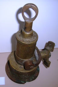
Equipment - Ships Log Measuring Rotator
... and governor to record distance travelled. Ships measuring log Insignia ...Used by all ships until replaced by more modern methods after c.1960. Used with clock recorder, log line and governor to record distance travelled.Ships log rotator and connecting eyeInsignia, T W Cherub 245, T Walker and Son Ltd. Birmingham Englandships measuring log -
 The Ed Muirhead Physics Museum
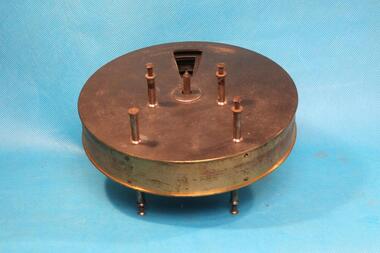
Instrument - Becquerel Phosphoroscope (incomplete), c1860-1880
The phosphoroscope was invented by Alexander Edmund Becquerel and used to measure the amount of time that a phosphorescent substance will glow after being irradiated by a brilliant source of light.The phosphoroscope consists of a round metal chamber with a pair of rotating discs inside, arranged so that no light can pass directly through the chamber. The discs have cut-out windows spaced equally at regular angular distances and are turned by the hand crank linked to a gear mechanism. The sample is placed in a specially designed holder into the small opening near the gearing, and it is exposed to the light source through the large rear condensing lens.Engraved on chamber: 'Phosphoroscope de E. Becquerel / J. Duboscq a Parisbecquerel phosphoroscope, phosphoroscope, optical instruments, phosphorescent, alexander edmund becquerel, jules duboscq, france -
 Flagstaff Hill Maritime Museum and Village
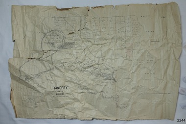
Map - Survey Map, F.F. McGovern, Yangery - County of Villiers, 1884
A surveyor was employed to measure the land designated as Yangery, County of Villiers, in the Borough of Warrnambool. The area on the map is similar to the earlier Farnham Survey undertaken by William Rutledge in the 1850's. Warrnambool was a Borough between 1863-1883. Coutours, waterways, sea and other significant points are shown. The distances are accurately measured. This survey map was used for planning future land sales, recreation areas and roads. WILLIAM RUTLEDGE (1806-1876) William Rutledge surveyed the land known as Farnham in southwest Victoria in 1843. His tenants made him a profitable business from working the land there. In 1863 Rutledge moved from nearby Port Fairy to Farnham and became very successful in breeding sheep, which he imported from J.R. Kirkham of Lincolnshire, England. He also bred horses on his land. The survey map of Yangery is important for its connection with renowned surveyor William Rutledge. The map shows the growth of landholders in the district when compared to the original Rutledge survey of the 1850's.Survey map of Yangery, titled "Yangery - County of Villiers". Printed on white paper, mounted on brown paper. c. 1863-1876. Comments printed on the Map include; Special Survey by William Rutledge, Photo-lithographed at the Department of Lands and Survey, Melbourne by W.J. Burson, Price 1/- [one shilling]. Scale is in Chains. Map has boundaries of Koroit Borough, Meerai, Purnim, Wangoom, Borough of Warrnambool, Mentions the Proposal of Tower HIll for Public Recreation. The map names the owners of the land at that time. Hand written pencil marks and figures and "Sauls fence" drawn on map. Hand written pencil markes and figures and "Sauls fence" drawn onto map. "For Department Use only". "Scale: 8 chains to 1 inch" flagstaff hill, warrnambool, shipwrecked-coast, flagstaff-hill, flagstaff-hill-maritime-museum, maritime-museum, shipwreck-coast, flagstaff-hill-maritime-village, county of villiers map, yangery district, w.j. burson, borough of warrnambool, koroit, purnim, meerai, wangoom, proposal of tower hill for public recreation, special survey by william rutledge, william rutledge, farnham, lincolnshire sheep, clydesdale -
 Bendigo Military Museum
Photograph - Royal Australian Survey Corps Surveyors in the Field – Project Cutlass, New Guinea, 1956 – 1957
... to measure base line distances between survey stations. Bob Skitch... to measure base line distances between survey stations. Bob Skitch ...This is a set of 23 photographs of surveyors and support staff in the field undertaking tasks in New Guinea 1956 – 1957. The surveyors were employed in the establishment of mapping and geodetic control for Project Cutlass, the “Ship-Shore” survey of the New Ireland province. In this survey operation surveyors used theodolites to observe horizontal and vertical angles and chains to measure base line distances between survey stations. Bob Skitch shown in photo .7P was in the 2nd year of his career in the Australian Army. He achieved the rank of Lieutenant-Colonel, and his last appointment was the CO of the Army Survey Regiment from 1976 to 1980.This is a set of 23 photographs of surveyors and support staff in the field undertaking duties during Project Cutlass located in New Ireland, New Guinea 1956 – 1957. The photographs were printed on photographic paper and are part of the Army Survey Regiment’s Collection. The photographs were scanned at 300 dpi. .1) - Photo, colour, 1956. Surveyors travelling main road from Kavieng to Namatanai, New Ireland. .2) - Photo, colour, 1956. Unidentified surveyors assessing recovery of their vehicle after bridge collapsed on west side of New Ireland. .3) - Photo, colour, 1956. Unidentified surveyors assessing recovery of their vehicle after bridge collapsed over flooded creek on west side of New Ireland. .4) - Photo, colour, 1956. Survey personnel L to R: Bev Uwins, John Lambie, Bob Thompson, New Ireland. .5) - Photo, colour, 1956. Survey base camp, New Ireland. .6) - Photo, black & white, 1956-1957. Geoff Helsham with possible human remains, New Ireland. .7) - Photo, black & white, 1956-1957. Bob Skitch undertaking survey observations using Wild T2 theodolite, New Ireland. .8) - Photo, black & white, 1956-1957. Chas Beach undertaking survey observations using Wild T2 theodolite, New Ireland. .9) & .10) - Photo, black & white, 1956-1957. Kev Parker (cook) New Ireland. .11) - Photo, colour, 1957. Brian Berkery taking a break, Top Manor Island, Lihir Island Group off New Ireland. Latitude -2° 46”, Longitude 152° 40”. .12) - Photo, colour, 1957. Survey base camp L to R: Chas Beach, Bev Uwins, Feni Islands, New Ireland. Latitude -4° 05”, Longitude 153° 45”. .13) - Photo, colour, 1957. A Hous Kiap. (Kiaps, known formally as district officers and patrol officers, were travelling representatives of the British and Australian governments), New Ireland. .14) & .15) - Photo, colour, 1957. L to R: Joe Farrington, Tom Royle Bob undertaking survey observations using theodolites from an improvised timber tower, New Ireland. .16) & .17) - Photo, colour, 1957. US Army ship FS216 used for ship-to-shore triangulation docked at Rabaul, New Britain. .18) - Photo, colour, 1957. US Army ship FS216 used for ship-to-shore triangulation docked at Kavieng, New Ireland. Sight target on top of mast. .19) - Photo, colour, 1957. Survey personnel onboard US Army ship FS392, L to R: Peter Frodsham, Bob Thompson, Doc Reid, John Underwood, remainder unidentified, New Ireland. .20) - Photo, colour, 1957. Survey base line party heading ashore, New Ireland. .21) - Photo, colour, 1957. Survey personnel rowing US Army assault boat L to R: Kev Parker, Chas Beach, folded up survey beacons overhanging stern, New Ireland. .22) - Photo, colour, 1957. Les Bailey onboard US Army ship departing Rabaul, New Britain for Brisbane. .23) - Photo, colour, 1957. Ron Newman onboard US Army ship departing Rabaul, New Britain for Brisbane. Active volcano in background..1P to .23P annotated on back – ‘Operation Cutlass’, personnel names, the year and the location. royal australian survey corps, rasvy, army survey regiment, fortuna, a, army svy regt, asr, surveying -
 Bendigo Military Museum
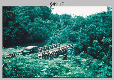
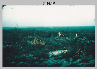
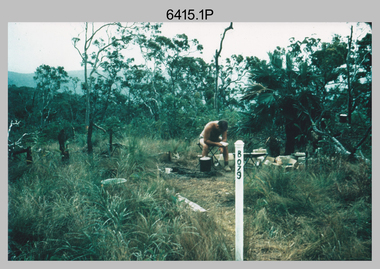
Photograph - Royal Australian Survey Corps Surveyors in the Field – Northern Territory and Queensland, 1959 – 1960
... and tellurometers to measure base line distances between survey stations... tellurometer to measure base-line distances NW of Mount Isa, QLD. .8... and tellurometers to measure base line distances between survey stations ...This is a set of 10 photographs of surveyors and support staff in the field undertaking duties in the Northern Territory and North Queensland in 1959 – 1960. The surveyors were employed in the establishment of mapping and geodetic control. In this era surveyors used theodolites to observe horizontal and vertical angles and tellurometers to measure base line distances between survey stations. Laplace survey observations seen in Photo .1P was a series of precise observations carried out at geodetic survey stations to determine astronomic latitudes, longitudes and azimuths to achieve maximum precision in the survey network. Laplace observations were necessary in a geodetic network at every 6th survey station, however the National Mapping Council specified at this time the spacing would be ideally between 4-6 survey stations. The cairn shown in photo .4P was built by RASvy as a landmark over a trigonometric survey station. It was dismantled in 1960 to enable re-occupation and survey observations. It was not restored to the condition shown in the photo.This is a set of 10 photographs of surveyors and support staff in the field undertaking duties in the Northern Territory (NT) and Queensland (QLD) in 1959 – 1960. The photographs were printed on photographic paper and are part of the Army Survey Regiment’s Collection. The photographs were scanned at 300 dpi. .1) - Photo, colour, 1959. Tony Slattery occupying a Laplace survey station on a hill in the Mount Young area of the NT. .2) - Photo, colour, 1959. Surveyors’ camp in the Mount Young area of the NT, L to R: Spencer Snow and Tony Slattery. .3) - Photo, colour, 1959. Surveyors’ camp in the Peckman Hill area, near Katherine in the NT. .4) - Photo, colour, 1959. Cairn on Trig Hill, Borroloola, NT. Built by Spencer Snow, Tom Royle and Jack McCabe. .5) - Photo, colour, 1959. Survey party taking a break next to their Austin Champ vehicle, in transit between Katherine, NT and Wyndam WA. L to R: Tony Slattery, Dave Owens, John Van De Graff. .6) - Photo, colour, 1960. Surveyors’ camp between Mount Isa, QLD and Borroloola, NT. L to R: Pat Cox and John Van De Graff prepare their meal on an open fire. .7) - Photo, colour, 1960. Surveyor - Dennis Woods undertaking survey observations, using MRA1 tellurometer to measure base-line distances NW of Mount Isa, QLD. .8) - Photo, colour, 1960. Unidentified surveyors assessing recovery of their stalled Studebaker truck vehicle after attempting a water crossing in the NT. .9) - Photo, colour, 1960. Unidentified surveyor making batches of bread at a camp in the NT. Seen in the photo placing a lid with hot coals onto the camp oven. .10) - Photo, colour, 1960. Unidentified survey party occupying a survey station on a hill in the Mount near the Lawn Hill area, NW of Mount Isa, QLD. A MRA1 tellurometer to measure base-line distances appear on the right side of the photo. .9) - Photo, colour, 1960. Unidentified surveyors assessing recovery of their stalled Studebaker truck vehicle after attempting a water crossing in the NT. .10) - Photo, colour, 1960. Unidentified surveyor making batches of bread at a camp in the NT. Seen in the photo placing a lid with hot coals onto the camp oven. .1P to .10P annotated on back – personnel names, the year and the location. royal australian survey corps, rasvy, army survey regiment, asr, army svy regt, fortuna, surveying -
 Bendigo Military Museum
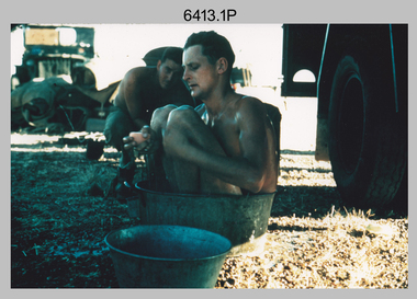
Photograph - Royal Australian Survey Corps Surveyors in the Field – North Queensland, 1958
... to measure base line distances between survey stations. Bob Skitch... survey observations, using MRA1 tellurometer to measure base-line... to measure base line distances between survey stations. Bob Skitch ...This is a set of seven photographs of surveyors and support staff in the field undertaking duties in North Queensland in 1958. The surveyors were employed in the establishment of mapping and geodetic control. In this era surveyors used theodolites to observe horizontal and vertical angles and chains to measure base line distances between survey stations. Bob Skitch shown in photos .4P to .6P was in the 2nd year of his career in the Australian Army. He achieved the rank of Lieutenant Colonel and his last appointment was the CO of the Army Survey Regiment from 1976 to 1980. The annotation on the back of photo .5P ‘Black foreground is where Bob Skitch boiled billy and started a grass fire’.This is a set of seven photographs of surveyors and support staff in the field undertaking duties in North Queensland in 1958. The photographs were printed on photographic paper and are part of the Army Survey Regiment’s Collection. The photographs were scanned at 300 dpi. .1) - Photo, colour, 1958. Surveyor in Nth QLD enjoying a bath. L to R: Don Cocker, Bob Thompson. .2) - Photo, colour, 1958. Don Cocker surveyor in Nth QLD, enjoying a bath. .3) - Photo, colour, 1958. Surveyors Nth QLD undertaking survey observations, using MRA1 tellurometer to measure base-line distances. L to R: Len Davies, Lou Sommer, John Van De Graff. MRA1 was covered to stop overheating. .4) - Photo, colour, 1958. Surveyors south of Richmond, QLD digging holes for the erection of a Bilby observation tower. L to R: John Van De Graff, Bob Skitch, Kev Moody, Mal Hayes, Don Gray .5) - Photo, colour, 1958. Surveyors south of Richmond, QLD erecting a Bilby observation tower. L to R: Tom Royle, Bob Skitch (on ground level), Mal Hayes. .6) - Photo, colour, 1958. Surveyors south of Richmond, QLD erecting a Bilby observation tower. L to R: Tom Royle, Bob Skitch, Mal Hayes, Jim McGill (on ground level). .7) - Photo, colour, 1958. Surveyors south of Richmond, QLD undertaking survey measurements from a Bilby observation tower..1P to .7P annotated on back – personnel names, the year and the location. Annotated on back of .5P ‘Black foreground is where Bob Skitch boiled billy and started a grass fire’.royal australian survey corps, rasvy, army survey regiment, asr, army svy regt, fortuna, surveying -
 Bendigo Military Museum
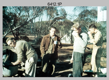
Photograph - Royal Australian Survey Corps Surveyors in the Field – Victoria, 1956 - 1958
... horizontal and vertical angles and chains to measure base line... horizontal and vertical angles and chains to measure base line ...This is a set of two photographs of surveyors and support staff in the field undertaking tasks in Victoria 1956 – 1958. The surveyors were employed in the establishment of mapping and geodetic control. In this era surveyors used theodolites to observe horizontal and vertical angles and chains to measure base line distances between survey stations. This is a set of 23 photographs of surveyors and support staff in the field undertaking duties in Victoria 1956 – 1958. The photographs were printed on photographic paper and are part of the Army Survey Regiment’s Collection. The photographs were scanned at 300 dpi. .1) - Photo, colour, 1956. Surveyors enjoying a tea break. L to R: Tom Gilbert (cook), Barry Broad, Tony Slattery, John Van De Graff. Taken at Boonoonar, a locality south of Mildura. .2) - Photo, colour, 1958. Surveyors taking a break from driving. L to R: Leo Bub, Bob Thompson. Taken at Puckapunyal..1P to .2P annotated on back – personnel names, the year and the location. royal australian survey corps, rasvy, army survey regiment, asr, army svy regt, fortuna, surveying -
 Bendigo Military Museum
Photograph - Royal Australian Survey Corps Surveyors in the Field – North Queensland and Torres Strait, 1961
... and tellurometers to measure base line distances between survey stations... and tellurometers to measure base line distances between survey stations ...This is a set of five photographs of surveyors and support staff in the field undertaking duties in North Queensland and Torres Strait in 1961. The surveyors were employed in the establishment of mapping and geodetic control. In this era surveyors used theodolites to observe horizontal and vertical angles and tellurometers to measure base line distances between survey stations. In photo .2P Joe Farrington is seen taking survey observations using a Tavistock V500 Series Tavistock theodolite at a survey station between the Edward River and Aurukun in the Cape York Peninsula. The Gulf of Carpentaria appears in the background. From 1957 helicopter transport of survey parties revolutionised transport in remote areas. The civilian helicopter was hired from TAA. This is a set of five photographs of surveyors and support staff in the field undertaking duties in North Queensland and Torres Strait in 1961. The photographs were printed on photographic paper and are part of the Army Survey Regiment’s Collection. The photographs were scanned at 300 dpi. .1) - Photo, colour, 1961. Andy Millar occupying a survey station on a hill in the Cape York Peninsula, QLD. .2) - Photo, colour, 1961. Joe Farrington taking observations with a V500 Series Tavistock geodetic theodolite at a survey station in the Cape York Peninsula, QLD. .3) - Photo, colour, 1961. Daryl Parker taking a break from survey observations on a hill located on Duaun Island QLD, in the Torres Strait, a few miles south of the PNG coastline. Hill height was 975 ft. .4) - Photo, colour, 1961. Three Torres Strait divers L to R: unidentified, Darku and Ray Mau Daryl standing behind a Tavistock geodetic theodolite on a hill located on Duaun Island QLD, in the Torres Strait, a few miles south of the PNG coastline. .5) - Photo, colour, 1961. Andy Millar holding meat from a small turtle on Duaun Island QLD, in the Torres Strait, a few miles south of the PNG coastline. An unidentified Duaun Island local appears in the background..1P to .5P annotated on back – personnel names, the year and the location. royal australian survey corps, rasvy, army survey regiment, asr, army svy regt, fortuna, surveying -
 Bendigo Military Museum
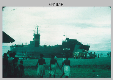
Photograph - Royal Australian Survey Corps Surveyors in the Field – PNG, 1962
... horizontal and vertical angles and tellurometers to measure base line... horizontal and vertical angles and tellurometers to measure base line ...This is a set of four photographs of surveyors and support staff in the field undertaking duties in Dogera, Milne Bay Province and Kerema, Gulf Province of PNG in 1962. The surveyors were employed in the establishment of mapping and geodetic control. In this era surveyors used theodolites to observe horizontal and vertical angles and tellurometers to measure base line distances between survey stations. From 1957 helicopter transport of survey parties revolutionised transport in remote areas.This is a set of four photographs of surveyors and support staff in the field undertaking duties in PNG in 1962. The photographs were printed on photographic paper and are part of the Army Survey Regiment’s Collection. The photographs were scanned at 300 dpi. .1) - Photo, colour, 1962. Unloading survey operation stores from a Landing Ship Medium (LSM) at Dogera, Milne Bay Province, PNG. .2) & .3) - Photo, colour, 1962. Hired civilian helicopter Bell 47G-2 helicopters operating at at Dogera, Milne Bay Province, PNG. .4) - Photo, colour, 1962. Survey party at survey station located near Kerema, Gulf Province southern PNG. L to R: Dave Owens, Keith Broadbent, with local villagers in background..1P to .4P annotated on back – personnel names, the year and the location. royal australian survey corps, rasvy, army survey regiment, asr, army svy regt, fortuna, surveying -
 Eltham District Historical Society Inc
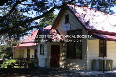
Photograph - Digital Photograph, Alan King, Original Kangaroo Ground Primary School No. 2105 building, Eltham-Yarra Glen Road, Kangaroo Ground, 28 December 2007
Kangaroo Ground's first school began in 1851 with 22 pupils from the district's ten families. It was a single room school located further south on the site, which also served as a Presbyterian church. The first teacher was Andrew Ross. The school building was used as a Post Office between 1854 and 1858 and during 1857 also served as a Court of Petty Sessions. With a growing farming community, a new building was warranted and the original Sate School No. 352 was closed and a new building, State School No. 2105 was oipened October 1, 1878. A residence for Head Teacher Henry Wallace School was erected in 1879 attached to the left of the school building. That residence is now home to the Andrew Ross Museum, which opened in 1993. Covered under Heritage Overlay, Nillumbik Planning Scheme. Published: Nillumbik Now and Then / Marguerite Marshall 2008; photographs Alan King with Marguerite Marshall.; p35 In a corner of the Kangaroo Ground Primary School playground stands an old weatherboard building. This structure, attached to the former teacher’s weatherboard residence facing Main Road, first served as a school in 1878. The former residence, built in 1879, houses the Andrew Ross Museum, which opened in 1993. It is named after the school’s first teacher,1 who also founded The Evelyn Observer newspaper, which began on the site in 1873. Later the printing presses were moved to brick newspaper offices by the Kangaroo Ground Hotel, which became the Shire of Eltham offices. However Kangaroo Ground’s first school began in 1851 for 22 pupils from the district’s ten families, in a slab building further south on this site. Andrew Harkness and other settlers campaigned for the building, which was built on half an acre (0.2ha) donated by local farmer, James Donaldson. Builder was Samuel Furphy, father of the novelist Joseph.2 The single room measuring 30 feet x 18 feet (9m x 5.5m), was unlined and the green slabs shrank, allowing the wind and rain entry through cracks except when they were stuffed with paper.3 The building served as a Presbyterian church as well as a school, where fees were 18 pence a week for education. Young men also attended evening classes there in winter. At one stage, a corner of the room was curtained off for the schoolmaster’s living space, and the platform, which was used for sleeping, was also the pulpit during church services. Teacher Andrew Ross also took church services when the minister was unable to attend, which happened frequently as he had long distances to travel on the bad roads. In 1857 the school building was also used as the Court of Petty Sessions, and from 1854 until 1858, it served as a post office. During the gold rush fossickers on their way to the Caledonia Diggings at Queenstown (now St Andrews) prospected the district, but did not remain long, as the fields were not rich in gold. But the farming community grew, until by 1878 the population warranted the building of State School No 2105 – the present one-roomed tongue-and-groove lined building measuring 49 feet x 18 feet (15m x 5.5m), to accommodate 60 children. The old school, No 352, was closed, and the new one opened on October 1, with Henry Wallace as head teacher, assisted by work mistress Annie Johnston. Early teachers included Messrs Smith, Hamilton and Prosser, with sewing teachers Misses Sweeney, Limerock and Oliver. In the early 1920s a small room was built on the front veranda of the teacher’s residence, and used as a State Savings Bank agency until about 1934. In 1928 the schoolroom’s three-tiered floor was replaced by a flat floor and teacher’s platform (which has since been removed). A half-glassed partition wall then divided the large room into two rooms in which the old style form-type desks were replaced with dual desks. The small playground, surrounded by pine trees and a picket fence, was extended in 1931 with an additional acre or so (0.4 ha) of land. During World War Two the school faced closure because of a fall to seven in the enrolment, but by 1946 it had increased again to 45. Mr Eric Morgan was head teacher and Mrs Margaret Banks was assistant head teacher, a position she held for ten years. In 1955, under the head teacher Mr V Gardiner, who taught there for 13 years, the school won a prize for the best-kept garden and school ground in the inspectorate. A district subdivision increased the enrolment in 1968 to 65 and a bus service was established. After the hall which had been used for lessons was demolished late that year, the pupils met in the original fire brigade meeting room (now the tennis club, diagonally opposite the general store). The new school building with a storeroom and staffroom was built in 1974.This collection of almost 130 photos about places and people within the Shire of Nillumbik, an urban and rural municipality in Melbourne's north, contributes to an understanding of the history of the Shire. Published in 2008 immediately prior to the Black Saturday bushfires of February 7, 2009, it documents sites that were impacted, and in some cases destroyed by the fires. It includes photographs taken especially for the publication, creating a unique time capsule representing the Shire in the early 21st century. It remains the most recent comprehenesive publication devoted to the Shire's history connecting local residents to the past. nillumbik now and then (marshall-king) collection, kangaroo ground, andrew ross museum, eltham-yarra glen road, kangaroo ground primary school no. 2105, kangaroo ground state school, state school no. 2105 -
 National Vietnam Veterans Museum (NVVM)
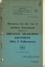
Booklet, Australian Army, British Army: Directions for the Use of Aartillery Instruments : Pamphlet No. 9: Distance Measuring Equipment MRA 2 (Tellurometer), 1961 (Copy 1), 1961
... Artillery Instruments Distance Measuring Equipment Tellurometer ...A blue coloured cardboard cover. the information is written in black ink. Top right hand corner is the number four which has been written in black texta. Une this is W.O. Code No. 9726. The top half of the cover is faded. There are three punch holes and two metal staples down the left hand side. Also contains Amendments No. 1 which is held together by a metal staple and is inside of the booklet. Top right hand corner reads 7610-66-013-9800/1. Under this reads W Code No 9726-2 (Aust) and this amendment is done by Army Headquaters, Canberra on the 1 Sep. 68. There are three punch holes down the left hand side of the amendment.australia - armed forces - service manuals, british army, artillery instruments, distance measuring equipment, tellurometer -
 National Vietnam Veterans Museum (NVVM)
Booklet, Australian Army, British Army: Directions for the Use of Aartillery Instruments : Pamphlet No. 9: Distance Measuring Equipment MRA 2 (Tellurometer), 1961 (Copy 2), 1961
... Artillery Instruments Distance Measuring Equipment Tellurometer ...A blue coloured cardboard cover. the information is written in black ink. Top right hand corner is the number five which has been written in black texta. Une this is W.O. Code No. 9726. Part of the top half of the cover is faded. There are three punch holes and two metal staples down the left hand side. Also contains Amendments No. 1 which is held together by a metal staple and is inside of the booklet. Top right hand corner reads 7610-66-013-9800/1. Under this reads W Code No 9726-2 (Aust) and this amendment is done by Army Headquaters, Canberra on the 1 Sep. 68. There are three punch holes down the left hand side of the amendment.australia - armed forces - service manuals, british army, artillery instruments, distance measuring equipment, tellurometer -
 Ringwood and District Historical Society
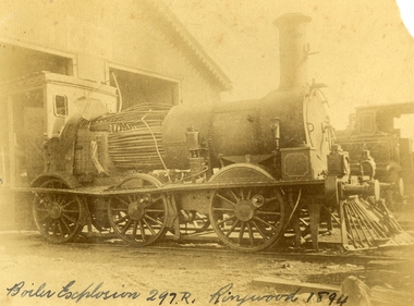
Photograph, Boiler explosion at Ringwood station 20th June 1894 for engine 297R. "Heard in Box Hill"
... measure the distance ? Witness: Yes; one of the plates was 209... measure the distance ? Witness: Yes; one of the plates was 209 ...Black and white photographs - 2 copiesTyped below photograph, "Boiler explosion at Ringwood station 20/6/1894. Heard in Box Hill". Article from newspapers:- Weekly Times (Melbourne, Vic. : 1869 - 1954), Saturday 27 January 1894, page 21 Official enquiry. The Board of Enquiry appointed by the Railway Commissioners to enquire into the causes of the boiler explosion which shattered the locomotive at Ringwood on Saturday night, assembled at the Railway department on Wednesday to commence its deliberations, The board consisted of Mr R. Fulton, engineer, C. W. McLean; engineer to the Marine Board, and Mr Mephan Ferguson, iron-founder. There is some difficulty at the outset about the constitution of the board; It was suggested that the Apt of Parliament contemplated that boards of experts, after the manner of the present one, needed, to have their appointments confirmed by the Governor-in-Council. The point, however, was not considered sufficiently important to prevent the board from proceeding with evidence. Robert Greyford, stationmaster at Ringwood, was the first witness. He said he saw the explosion on Saturday night at about twenty minutes to 8. There was a rush to the engine to see what had happened, and the driver and fireman were both found on the platform of the engine. The driver seemed badly hurt, but the fireman, to all appearances, was not so badly injured. They were both attended to and sent up to Melbourne by the last suburban train. Witness had a look at the engine and found the dome and all the plates round the boiler blown clean, away. The springs were also blown clean away. The Chairman (Mr Fulton) : Did you measure the distance ? Witness: Yes; one of the plates was 209 yards away. A piece from the top of the boiler 15 pounds in weight he found driven into the hard beaten track 410 yards away. Several pieces of boiler plate were found scattered at various distances. The buildings roundabout were injured. The Chairman; Did you notice anything peculiar about either of the driver or the fireman ? — No ; nothing wrong, with either of them. If the engine was blowing off at all, it must have been very light. In your opinion, were they perfectly sober ? — Perfectly. In approaching the station, is there a down or an up grade? — A very slight down grade. How is the road from Healesville ? — Up and down all the way. It is down, grade for about 200 yards coming into Ringwood station. They shut off ; steam about a quarter of a mile away, and come in at a good pace. They generally put on 15 pounds of steam while they are in the station. Mr Ferguson : Had the driver the usual load on ? — Yes ; about the usual load. Witness added that he had known the driver personally for about 10 years, and he had always been a careful, steady, sober man. He did not know the fireman so well. John Palmer, porter at Ringwood station, also saw the explosion. He was attending to the train on its arrival. He was knocked down by the force of the explosion. When he got up he saw the engine driver being carried into the office covered in blood. He noticed nothing peculiar about the driver and fireman, nor about the engine. Mr McLean : How far were you from the engine when you were knocked down ? — From ten to fifteen yards. William Paul, the guard of the train to which the injured locomotive Was attached, said he was looking at the engine at the very moment the explosion occurred. It seemed to come from exactly under the dome. The force of it took him off his feet. He was about 15 yards from the tender. When he rose he tried to reach the engine, but could not do so on account of the steam and coal dust. He called out to know whether any of the passengers were injured, and got no response, so that he concluded they were all right. All the lamps but about half dozen were extinguished by the force of the explosion, although the glass was not broken. He could testify most distinctly that the driver and fireman were both sober. The driver was a man who never drank. The steam started to blow off about a minute and a half before the explosion took place. The last place at which the engine took water was Healesville. The Chairman : Do yon know anything of the quality of the water there ? Is it creek water ? — Yes ; it comes from the Graceburn River. You never heard of its quality ?— No. How long have you known this engine on the road— About 13 months. Hew long have you known the driver on this line ? — About six weeks. I have known the fireman several years. The driver was a strict teetotaller, and I never saw the fireman take anything to drink in his life. Mr T. H, Woodroffe, chief mechanical engineer of the Victorian Railways, produced a report he had written to the secretary, about this explosion. The document gave facts concerning the engine and the explosion. It stated that the rapture seemed to have occurred at the rim of the plates adjoining the fire box. The engine was built at the Phoenix Foundry, Ballarat, in 1883. It was repaired at various times, the last time being in July of last year when it was sent to the Port Melbourne shops, and was then tested to a cold water pressure of 195 and found all right. It was the custom to overhaul all locomotives about every five years. The Chairman : There were no very heavy repairs in July, 1893; were there? — Not to the boilers. The shop manager's report says that the plug and safety tap holes were repaired, five new copper studs put in firebox, ash-pan door repaired, tender cleaned and overhauled, and studs re-rivetted, and boiler tested to pressure of 195, cold water. Mr Woodroffe read the report of the repairs effected to the boiler in December, 1888. That would be the time the plate was put in the boiler. On that occasion three new plates were put in the bottom and the boiler tested up to 195. The Chairman: Do you keep a record of the water used ?— Yes, the water in this case, I think, came from the Maroondah scheme. Mr Woodroffe said boilers were examined front time to time in the running sheds. In his opinion every possible care had been taken to keep the engine in proper care. There might, however, be lessons learnt from this. The Chairman: No doubt. From his examination of the plates [the] witness did not think the state of them could have been detected from the outside. There were no signs of leakage or sweating or anything of that sort. The next witness- was Walter Stinton, workshop manager at Newport and he said that the injured engine had been repeatedly repaired under his charge. He gave a technical account of the repairs effected on various occasions. The testing of locomotives was under his special notice. They had a high pressure pipe running; round the works, and a pump set at 2001b. When the boiler was pumped full of water the pressure when applied up to 1951b. The board appointed by the department to inquire into the Ringwood locomotive boiler explosion sat again at Spencer street on 25th inst. Mr R. Fulton presided and the other members of the board were. Mr Mephan Ferguson and Mr C. W. McLean. Charles Grubb, foreman of the boiler-makers at the Newport workshops, said he had inspected the pieces of plate that had been blown out of the engine, and after examining them, pointed out to the Chief Mechanical Engineer the portion where the plate had started to burst. It was under the lap, on the right hand side of the boiler. The grooving might be accounted for by bad water. During the past twenty years he had examined all the boilers that came into the Williamstown workshops, and while some were hardly marked at all, others were very badly eaten away. The practice was to cut out the defective portions. In this case the boiler was repaired in a similar manner. The Chairman : Can you suggest any other way of repairing so as to prevent accident ? — No, unless by taking out a plate on one side from the joint, and carrying it further up so as to avoid the joints meeting, or by taking out the plate altogether. What would.be the cost .of putting in a new " plate I—Perhaps about double the price; but I wouldn't recommend that course. It would be putting a new plate against plates that have been in use ten years or so and that would not be advisable. I think the present system better. I consider the present system of repairing the best. This is the first we have had so bad like that, to my knowledge. You attributed this to bad water. Is there no other probable cause ? — Well; unless the iron be bad. This was Lowmoor iron. I think this accident was caused by the eating away of plates. This one was the worst I have seen, for the short time it had been running. We use three classes of iron — Lowmoor, Monkbridge and Bowling. By Mr Woodroffe (Chief Mechanical Engineer) ; There are engines still running that were repaired at the same time as this one, in 1888, and. in the same way. These are engines 339 and 333. They have been recently examined and are in splendid order. What in your experience, is the age of a boiler on the Victorian railways? — From 17 to 20 years our earlier boilers stood. The later boilers don't stand so well. How is that? — There is difference in construction, and the material is lighter. The old boilers had thicker plates. Have you been asked in any way to curtail boiler affairs? — No, sir; nor in any way. You have never hesitated to carry out any necessary repairs? — Never. Our orders have been to exercise every care in examining, repairing and renewing boilers. Witness said that his practice was when an engine came into the workshop to find out how long she had been running. If over five years, he informed the workshop manager, and they thought it necessary the tubes were taken nut. If everything was in good order witness reported to the manager. The cost of taking out the tubes and putting them in again was about L20. Mr Woodroffe : Have you ever hesitated to repair a boiler on the score of expense ? — No, never. Mr McLean : Hew do yon ascertain whether a boiler requires repairs?— I keep a record of every boiler examined. From every boiler that comes in I have the dome covers taken off, and when it is practical I get inside. l can almost tell from the top of a boiler what the bottom is like. If there is any doubt about it I have the tubes taken out. If I have suspicion of defective plate I cause to have bored a triangle in the plate at the point where there is the most wear. There is a travelling inspector who visits all the running sheds of the colony except Port Melbourne and tests the boilers. He reports to us and we note what he points out. Alfred Thompson, locomotive inspector of the eastern section, said he knew this engine, 297R. He read a list of her repairs. He heard of the accident on Saturday night and went up to Ringwood. The Chairman : Did you ever notice anything peculiar about the engine? — No, I considered her A1 and would not have hesitated to have put on 140lb pressure owing to the repairs she had undergone. Witness considered that the explosion was caused by the expansion and contraction of the plates ; and, no doubt, the plate had been eaten away through bad water. The other side of the boiler showed: signs of corrosion: By Mr Woodroffe ; Is every care taken with the boilers ? — Yes, every possible care is taken for the safety of boilers, Weekly Times (Melbourne, Vic. : 1869 - 1954), Saturday 27 January 1894, page 7 EXPLOSION OF A LOCOMOTIVE BOILER, NARROW ESACPE FROM FATALITIES. THE DAMAGED ENGINE. [See drawing of loco – saved in “Railways” folder] The explosion of a locomotive boiler at Ringwood on Saturday evening, formed the subject of much discussion in railway circles on Monday. The Minister arrived at the office at an unusually early hour and immediately entered into a consultation with the acting chairman, Mr Kibble, and Mr Commissioner Murray. As the result of the interview it was resolved to ask three gentlemen of acknowledged engineering experience to sib as a board with the . object of inquiring into the cause of the accident and furnishing a report. Mr Richardson and the Commissioners are tally seized of the importance of having a searching investigation into the accident, and, with Mr Murray, the former went to Ringwood to inspect the scene of the disaster. They will he accompanied by Mr Woodroffe. During the morning no official report had come to hand from the driver or fireman of the engine in reference to the accident, but that is thought to be due to the circumstance that they have not sufficiently recovered to be able to give a circumstantial account of what occurred. The engine was one of the old R's, and, Mr Kibble pronounced them to be about the best class of engines used. So far nothing can be said as to the probable cause of the accident, as the broken plating of the engine has not been submitted to the inspection of experts. Weekly Times (Melbourne, Vic. : 1869 - 1954), Saturday 27 January 1894, page 7 STATEMENT BY THE FIREMAN. This morning Thomas Miles, fireman on the engine the boiler of which exploded on Saturday night, is suffering from an injury to the spine, as well as a very severe shaking to the system. He states that he was fireman on the engine attached to the train which left Healesville on Saturday evening, at ten minutes to 8. Everything went all right until Ringwood was reached, when, .just as the train was about to continue its journey, a load explosion took place and Miles remembers nothing more until he was picked np on the platform ; and found himself suffering from a pain in the back, and an injury to his arm. He cannot think of any reason which could have caused the explosion, as there was plenty of water in the boiler, and everything seemed working all right. Mr R. Fulton, consulting engineer, of Queen street; Mr McLean, a member of the Marine Board ; and Mr Mephan Ferguson, engineer, have consented to act as a board to inquire into the cause of the engine boiler explosion at Ringwood on Saturday evening. The board has been appointed under section 117 of Act 1135, which provides that the Governor-in-Council may direct the taking of a such a step. Mr1 Fulton will act as chairman of the board, which met for the first time at the railway offices, Spencer street, this forenoon. Before separating the members of the Board paid a visit to the Prince's Bridge locomotive sheds in company with Mr Woodroffe, the chief mechanical engineer, for the purpose of inspecting the shattered boiler. It has been stated that the explosion is known to have been caused by a flaw in a plate which was put on the boiler about four years ago, but enquiries have tailed to elicit anything in support of that view. The engineers connected with the department are not inclined to say anything on the subject. Weekly Times (Melbourne, Vic. : 1869 - 1954), Saturday 14 April 1894, page 20 The Ringwood Boiler Explosion, The Minister of Railways has received the supplementary report of the board appointed by him to investigate the circumstances connected with the explosion of a locomotive boiler at Ringwood. In their first report the board did not attach blame to anyone. Mr Richardson felt satisfied that the responsibility of having the engines properly inspected and overhauled periodically could be fixed if the inquiry were extended. He therefore referred the matter again to the Board, who took further evidence. In the report now furnished, the Board hold Loco. Inspector Thompson blameable, but point out as a mitigating circumstance that he had not received "written instructions" respecting inspections and overhauls. Weekly Times (Melbourne, Vic. : 1869 - 1954), Saturday 7 July 1894, page 32 The Ringwood Boiler Explosion. The Minister of Railways takes exception to the tone of a paragraph appearing in a morning contemporary respecting the Ringwood boiler explosion. It makes it appear that Mr Richardson has referred the report of the board which considered the facts connected with the explosion to the Crown solicitor simply because he differed from the finding of the board. The Minister explains that when he received the report he found that the responsibility for having boilers properly inspected and overhauled had not been clearly fixed. He personally obtained farther evidence on that point, and arrived at a conclusion, from which the commissioners differed. As he did not like to take upon himself the responsibility of deciding upon the effect of the evidence, he submitted the matter to the Crown Solicitor, but that officer did not furnish him with the information sought. He has, therefore, referred the question to the Attorney-General, together with the draft of a regulation respecting boiler inspections and overhauls in the future. Mr Richardson says that his whole aim is to have the responsibility positively fixed. Weekly Times (Melbourne, Vic. : 1869 - 1954), Saturday 28 April 1894, page 23 The Minister of Railways has completed his consideration of the supplementary report received by him from the Ringwood Boiler Explosion Board. The report, it will be remembered, held Loco-Inspector Thompson blameable for the non-inspection of the boiler, but considered there was extenuating circumstances. There was a certain amount of doubt as to the absolute instructions given for overhauling engines periodically. Mr. Richardson is sending the report on to the Commissioners with instructions that the responsibility respecting inspection of boilers shall be made clear for the future.