Showing 4208 items matching "engines"
-
 Bendigo Historical Society Inc.
Document - CENTRAL NELL GWYNNE MINE: RESTORATION OF POPPET LEGS
Handwritten paper regarding restoration of poppet legs, request for additional area of land to cover area occupied by engine beds and engine house and painting of the legs with primer. Small piece of paper mentions South Nell Mine commenced operations 7//2/41 and Mine Reports Mr. Jackman from the Mines Dep't has had typed, Carlisle United, Central Nell Gwynne Mine and Fortuna Hustlers. Images 3509.10a,10b,10c,10d,10emine, gold, central nell gwynne mine, central nell gwynne mine, restoration of poppet legs, mr jackman, mines dep't, carlisle united, central nell gwynne mine, fortuna hustlers -
 Port Melbourne Historical & Preservation Society
Photograph - Sandridge Station, 1862
Image of Sandridge station (Port Melbourne) in 1862. Shows steam train, goods carriages, workers and sheds. The driver of Engine No 8 is Mr W Pattison and the fireman Mr D McFarlane. The engine in the background is No 5, driver Mr P Turville. Standing at the side of No 8 are messrs Bond and Williams, the lessees of the refreshment rooms.t thr front buffer are Mr Moss, lightman, with a son of Mr Pattison.The Station Master Mr Neville is at the extreme right. Other people unknown.transport - railways, sandridge railway station, william pattison, d macfarlane, thomas turville, bond, williams, moss, neville -
 Stawell Historical Society Inc
Photograph, "D" Class Steam Trains -- 2 Colour Photos and one black and white at Cato Park
2 Coloured photos of D Class Steam Rail Locomotive and one Black & White of same engine at Cato Park. c 1974. The engine was subject to vandalism and removed in 1988. The black & white photo of D3 608 was copies from a railway magazine. Two coloured photos & one black & white photo of "D" class 608 Steam rail Locomotive taken at Cato Park. "D" 608. Inscription on the back of both colour photos, "Vec 74. D Class Loco at Cato Park". On the black & white photo " D3 608 one of the numerous and popular D3 class, preserved in a park in Stawell, 2nd April 1978".railways. -
 Port of Echuca
Functional object - Boiler engine, 1927
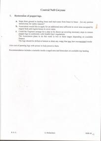
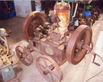
This is the Ruston and Proctor engine and boiler from the PS Little Wonder built by R Barbour, Cornella NSW. It was launched in December 1878. Owned by Murray River Sawmills, it was used for logging operations until 1904, when the vessel was dismantled. The engine and boiler was purchased by the Robins family and ran a pump on their property by the Goulburn River. The boiler was later condemned by the engine continued to be used with steam supplied by another boiler up until the 1950s. Now considered to be beyond repair. A good example of the technology and industrial history of northern Victoria and along the Goulburn River. boiler, steam display, steam garage, ruston and proctor -
 Flagstaff Hill Maritime Museum and Village
Equipment - Dentist Drill, Late 19th century
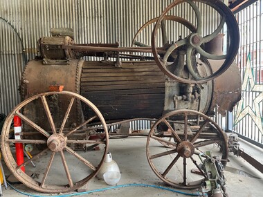
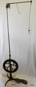
The design of this and other similar treadle powered dental engine (or dentist drill) was in common use by dentists from the 1870’s into the 1920's. When electricity became accessible to most communities the electrically powered dental engines began to take over from the treadle power. Over the ages teeth were extracted using picks and scissors and other gouging instruments. Bow drills, hand drills and even a "bur thimble" drill were later used to prepare cavities for filling. Some drills were made bendable by attaching flexible shanks between the metal bur and the handle, giving access to the teeth at the back of the mouth. Other mechanical devices were introduced along the way, such as clockwork drills, but they were hard to handle and inefficient. Over the centuries “dentistry has been performed by priests, monks and other healers. This was followed by barbers; the barber’s chair may well have been the precursor to the dental chair. “(SA Medical Heritage Society Inc.) In 1871 James Morrison patented the first commercially manufactured 'foot treadle dental engine', the first practica dental engine although others had been introduced as early as 1790 (by John Greenwood). Handmade steel burs or drills were introduced for dental handpieces, taking advantage of the significant increase in the speed of the drill. In 1891 the first machine-made steel burs were in use. The treadle drill reduced the time to prepare a cavity from hours to less than ten minutes. In 1876 the Samuel S. White Catalogue of Dentist Instruments listed a 12 ½ inch wheel diameter dental engine, with 14 bright steel parts, for sale at US $55 In today’s market, this is the equivalent to US $1200 approx. The specifications of that dental engine are very similar to the this one in our Flagstaff Hill Maritime Village’s collection. It is interesting to note that workings of a similar treadle dentist drill were used and modified to power a treadle spinning wheel of one of the volunteer spinners at Flagstaff Hill Maritime Village. The foot treadle dental engine was a milestone in dental history. “Historic importance of treadle powered machines; they made use of human power in an optimal way” (Lowtech Magazine “Short history of early pedal powered machines”) The invention of a machine to speed up the process of excavation of a tooth lead to the invention of new burs and drills for the handpieces, improving speed and the surgical process of dentistry. They were the fore-runner of today’s electrically powered dental engines. This treadle-powered dentist drill, or dentist engine, is made of iron and steel and provides power for a mechanical dental handpiece that would be fitted with a dental tool. On the foot is painted lettering naming it "The Brentfield" and there is a fine line of light coloured paint creating a border around the name. The paint under the lettering is peeling off. The drill has a Y-shaped, three footed cast iron base, one foot being longer than the other two. A vertical frame is joined into the centre of the base, holding an axle that has a driving-wheel (or flywheel) and connecting to a crank. A slender, shoulder height post, made from adjustable telescoping pipes, joins into the top of this frame. On the post just above the frame is a short metal, horizontal bar (to hold the hand-piece when it is not in use). A narrow tubular arm is attached to the top of the stand at a right angle and can move up, down and around. There is a pulley each side of the joint of the arm and a short way along the arm is fitted a short metal pipe. A little further along the arm a frayed-ended cord hangs down from a hole. At the end of the arm is another pulley and a joint from which hangs a long, thin metal pipe with two pulleys and a fitting on the end. A treadle, or foot pedal, is joined to the long foot of the base, and joined at the toe to the crank that turns the driving-wheel. The metal driving-wheel has a wide rim. Touching the inside of the rim are four tubular rings that bulge towards the outside of the driving-wheel, away from the pole, and all meet at the hub of the axle. The axle fits between the inside of the driving-wheel and the frame then passes through the frame and is attached on the other side. The driving-wheel has a groove around which a belt would sit. The belt would also fit around a pulley on the arm, at the top of the post. The pulley is joined to a rod inside the arm and this spins the drill's hand-piece and dental tool holder. The foot pedal has a cross-hatch pattern on the heel and the ball of the foot has tread lines across it. The end of the toe and the instep areas have cut-out pattern in them. "The ____/ Brentfield / __ DE IN L___" (Made in London) painted on the long foot of the base. Marked on the drill connection is “Richter De Trey, Germany”flagstaff hill, warrnambool, shipwrecked coast, flagstaff hill maritime museum, maritime museum, shipwreck coast, flagstaff hill maritime village, great ocean road, dentist, teeth, dental drill, dental engine, treadle drill, foot powered drill, treadle engine, orthodontics, dental surgery, james morrison, the brentfield, richter de trey, german dental fitting, london dental drill -
 Orbost & District Historical Society
black and white photograph, C1890
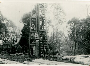
This photograph shows the construction of the first bridge over the Snowy River at Orbost being built. a copy was also donated by Gil and Heather Richardson. The first pile bridge over the Snowy River was just completed by Mr Jim Granter when the 1891 flood took out the centre,. There were differences of opinion as to whether the council should pay . The Shire Secretary, Mr John Draffin, persuaded them to honour their obligations. Mr Granter and Mr Clarke finished it as a suspension bridge which was opened by Mrs William Watt. Soon after a mob of cattle stampeded, the weight snapped the cable, letting one side sag. Mr R.P. Cameron repaired it and this bridge remained until 1922. "In 1890 the contract for a bridge was let to Mr James Granter for £1450. This structure with additions and improvements made to it was to cost the ratepayers about £2,500, and its erection was proceeded with in a very satisfactory manner until, just as the greater-part of the work had been completed, the flood of 1891 came down on it, piling up mountains of logs, timber and debris against the piers, which had not been made wide enough apart to allow for. contingencies of this kind. The structure held out bravely until the turn of the flood and then gave way with a crash, about five bays from the centre disappearing in the stream." ( Snowy River Mail August 12 1893)This is a pictorial record of the construction of the first bridge over the Snowy River.A black / white photograph of four men working on the construction of a new bridge and its pylons a man is standing on a timber tower/ derrick. There are logs in the foreground, trees in the background. sheds on the left and possibly a steam engine.on back - "first bridge - 1st pile being driven"snowy-river-bridge granter-jim bridge -
4th/19th Prince of Wales's Light Horse Regiment Unit History Room
Document, 4th/19th Prince of Wales's Light Horse Regiment, Cars Armoured Staghound DONT'S, 1960's
A single page listing 16 things not to do with regard to the Staghound, such as - "Don't start the engines before carrying out first parade service", and, "Don't traverse the turret unless the turret lock is fully disengaged"staghound armoured car -
 Bendigo Historical Society Inc.
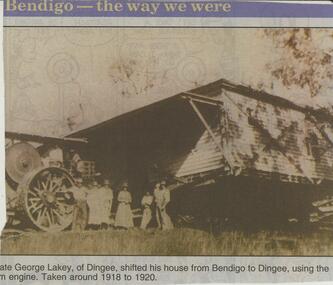
Newspaper - JENNY FOLEY COLLECTION: GEORGE LAKEY
Bendigo Advertiser ''The way we were'' from 2001. George Lakey, of Dingee, shifted his house from Bendigo to Dingee, using the steam engine. Taken around 1918 to 1920. The clip is in a foldernewspaper, bendigo advertiser, the way we were -
 Bendigo Historical Society Inc.
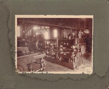
Photograph - A.HARKNESS + CO, C 1907
Sepia toned, mounted on green board. Interior of engine room, showing machines with large pistons, drive shafts and fly wheels. Inscription: plague on front of machine 'A. Harkness & Co | Engineers | 1907 | Bendigo'.A. G. Levy, (Eaglehawk photographer)organization, business, a.harkness + co -
 Bendigo Historical Society Inc.
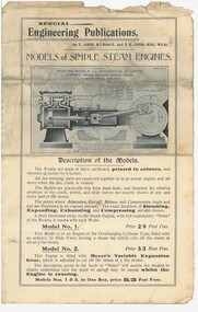
Document - MINING IN BENDIGO COLLECTION: WORKING MODELS FOR ENGINEERING STUDENTS
Printed document titled: Models of Simple Steam Engines by T. Jones, M. I. Mech. E. and T. Gilbert Jones, M. Sc., Wh. Sc. Includes descriptions of models. Four pageseducation, tertiary, models for engineering students. -
 Bendigo Historical Society Inc.
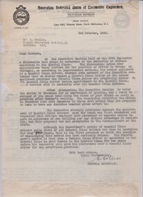
Document - BADHAM COLLECTION: LETTER TO R. HUDDLE, RE SENIORITY OF DRIVERS TO SPECIAL CLASS
Document: carbon copy of letter from C. Collins, General Secretary, to R. Huddle, Branch Secretary, Bendigo, dated 2nd. October, 1939, re special class engine drivers and seniority, and pay.organisation, union, a.f.u.l.e., huddle, collins, drivers, engine drivers, victorian railways, union -
 Tatura Irrigation & Wartime Camps Museum
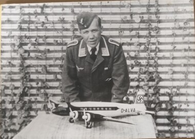
Photograph, Peter Mueller, 1940
Black and white photograph of Peter Mueller standing in front of a hut covered in foliage. On a table is a 4 engined model plane, passenger, black and white with D-Alva on the plane and the swastika on the perpendicular tail section.D-Alva Swastika peter mueller, model planes, camp 13 -
 Bendigo Historical Society Inc.
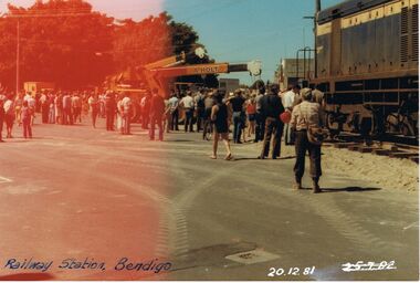
Photograph - JORDAN COLLECTION: BENDIGO RAILWAY STATION, 20th December, 1981
Colour photo of Bendigo Railway Station taken on 20 December 1981. The presence of two cranes indicates that Engine R711 being removed from one set of tracks and placed on tracks into the gardens at the station.bendigo, tourism, railway station -
 Sunbury Family History and Heritage Society Inc.
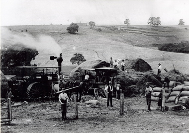
Photograph, The Nook
The photograph was taken in The Nook. Terence O'Brien rented the land from Goonawarra from the 1890s to 1905 where he grew cereal crops. The terraces on the hillside were built to grow vines when the property was one of the first vineyards in the area. The men in the image are from L-R: Mr. Heath in the white cutter owned the chaff cutter, John Leyden with hand on fence, Michael Dillon, Terence O'Brien and Phil Ratile are on top of the haystack, Andy Burke standing with hand on hip.The growing and harvesting of cereal crops was an important agricultural industry in the early days of Sunbury's settlement by both the Indigenous People and Europeans.A non-digital photograph black and white photograph of eleven men gathering hay with the aid of a steam traction engine in a wide open valley. A hillside in the distance has been terraced and there is a house on the hill in the distance.the nook, terence o'brien, andy burke, mr. heath, michael dillon, philratile, goonawarra, vineyards -
 Bendigo Historical Society Inc.
Document - MINING REPORTS - GT. NORTHERN WINDING ENGINE
Handwritten quote from the Sec. Mines Report for 1901 Page 79 by E. R. Meekison, Senior Inspector of Mines. Quote gives a detailed description of the winding engine manufactured by Messrs. Roberts and Sons.document, gold, mining reports, mining reports, gt northern winding engine, sec mines report for 1901 page 79, e r meekison, messrs roberts and sons, a richardson -
 Bendigo Historical Society Inc.
Document - NEW CHUM & VICTORIA LINES OF REEF - NOTES ON NEW CHUM & VICTORIA
Handwritten notes on New Chum & Victoria. Winding Engine Pair 22 in cylinders. Two valves to each cylinder (Corliss?). One boiler - steel. 26 ft x 6 ft 6 ins diameter. Reference: T. M. Hooper, Mining Manager, Sth Bellevie United Mine in machinery. Report to His Directors probably 7 /11/1885. On the back with scribble over it, are some notes re Bendigo was making its own winding engines, air compressors and crushing machinery so efficiently that the Senior Inspector of Mines, Mr. E. R. Neekison in a report to the Secretary for Mines in 1884 was emphatic that the best batteries, winding engines and gear have all been made in Sandhurst. Machinery made in Sandhurst was superior to any others in the colony for this class of work.document, gold, new chum & victoria lines of reef, notes on new chum & victoria, t m hooper, sth bellevu united mine, mr e r meekison, new chum, garden gully, hustler's, sheepshead line -
 Trafalgar Holden Museum
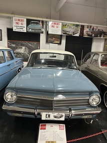
Vehicle - EH Holden special sedan, August 1963 - February 1965
It was the first Holden to incorporate the new "Red" engine, with a 7 main bearing crankshaft instead of the 4 main bearing crankshaft used in the "Grey" engine. The larger capacity 149 ci (2400cc) engine was first only sold attached to a three-speed manual gear box or the "Hydramatic" three-speed automatic transmission with a (column shift). Although the Controlled Coupling Hydramatic used in the EH was actually a four speed, it effectively worked as a three speed unit except at full throttle. The 179 ci (2900cc) engine was initially only sold with the "Hydramatic" three-speed. The first EH with a 179 ci engine and a manual gear box was called the "EH-S4", fitted with an up-graded manual gear box, with stronger gears than the 149ci gear box and an up-graded clutch. The three-speed manual (column shift) gear boxes had no synchromesh on first only second and third 'top gear'It was the first Holden to incorporate the new "Red" engine, with a 7 main bearing crankshaft instead of the 4 main bearing crankshaft used in the "Grey" engine. The larger capacity 149 ci (2400cc) engine was first only sold attached to a three-speed manual gear box or the "Hydramatic" three-speed automatic transmission with a (column shift). Although the Controlled Coupling Hydramatic used in the EH was actually a four speed, it effectively worked as a three speed unit except at full throttle. The 179 ci (2900cc) engine was initially only sold with the "Hydramatic" three-speed. The first EH with a 179 ci engine and a manual gear box was called the "EH-S4", fitted with an up-graded manual gear box, with stronger gears than the 149ci gear box and an up-graded clutch. The three-speed manual (column shift) gear boxes had no synchromesh on first only second and third 'top gear'Two tone, blue body and white roofon the boot of this car there is a 179 badge stating that this car was powered by the larger motor available. There was also a "Hydra-matic" badge showing this vehicle was fitted with an automatic transmission. Registered number 63454-Hholden, 1963 - 1965, car -
 Federation University Historical Collection
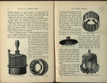
Book, Machinery for Metalliferous Mines, 1894, 1894
The 1st edition of this famous work, giving an excellent account of the machinery used in late 19th century metal mining in the UK and overseas is very rare. It covers a wide range of equipment - pumps, steam engines, drills, winding engines, stamps & concentration mills, aerial ropeways, tramways and early uses of electricity etc. Brown hard cloth covered book. xvi 564 pages with additional advertisements, with over 300 illustrations and drawings, some fold out. Chapters include Water as a motive power, Wind engines and ventilating machinery, Steam boilers/engines and oil engines, hoisting machinery, draining of Mines, pumping engines, rock drilling machinery, boring machinery, concentration machinery, sizing and classifications trommels, joggers and jigging, fine concentration, milling of gold ores, milling of silver ores, amalgamation plates and machinery, dry and roasting machinery, chlorination and cyandide processes for the extraction of gold, electricity as a motive power for mining, electric lighting and blasting, aerial wire ropeways, transport by rail and road. There a a number of lovely line illustrations in the book including: Poncelot's undershot waterwheel; Fromont furnace;Victor turbine; Pelton waterwheel; Root's positive blower;Cross section and front elevation of Lancashire boiler; Robey's Compound Mill Engine; Portable Winding Plant; Iron Pit Head Gear ; Loading Arrangement in an Incline Shaft; kibble; Worthington Pump; California Pump; Scram's Air Compressor; Rock drill Bits; Special Sharpening tools; Boring tools;Rotating Picking table; Ore Feeder; roller crusher; stamp battery; round buddle; slime table; vanner; amalgamating plant; belt elevator;roasting furnace;splicing wire rope; capel; tipping waggon;mining, cornish pump, linkenbach table, water wheel, ventilation, oil engine, california, america, water, steam boilers, steam engines, oil engines, pumpimg, rock drilling, boring, jiggers, milling, silver, gold, drying and roasting, chlorination, cyaniding, lead, zinc, copper, electricity, electric lighting, wire ropes, transport, wind engine, poppet head -
 Bendigo Historical Society Inc.
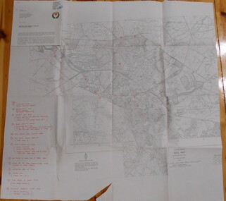
Map - BENDIGO HISTORICAL SOCIETY COLLECTION: EAGLEHAWK MINE MAP
Base map Australian map grid of Eaglehawk area. Map has letter attached from the Department of Conservation, Forests and Lands, 22 March, 1990, addressed to Felicity Kingerlie, BHS, requesting information regarding the historic mining sites marked on the map. Sites marked are: A. Golden Age Mine, engine mountings present B. Johnson's No. 2 Mine, engine mountings, old boiler foundations C. Johnson's No. 1 Mine, mullock retaining wall made from sandstone, engine mountings, remains of old building demolished? D. Toma's Eucalyptus Factory, old boiler still there, boiler shed, chimney (remnants of) outlet drain, distilling vats, dam, remnant of winch. E. New Argus Mine,mullock heap F. New Moon Mines Dams (1) stone walls G. North Lightning Hill Mine, engine mountings, quartz retainer wall, Pascoe and Simmons open cuts and other open cuts here too H. New Prince of Wales Mine and Poppet Head I. Quarry site for stone, excavation (for miners cottages in Clarke Street) J. Lancashire open cut mine K. Virginia Hill (cynaide vats etc) L. South Prince of Wales mine, now capped and fenced M (possibly ) Catherine United Mine, engine mountings, battery mountings?bendigo, mining, eaglehawk mines -
Moorabbin Air Museum
Book (Item) - Mirage Iiie Stressing Data Book Ii Wing Stress Analysis
Description: Mirage ATAR Engines - Quality Engineering Reports Level of Importance: . -
Moorabbin Air Museum
Manual (item) - Mirage III ATAR 09C Engine General Revision 11, ATAR 09C Revision Generale 11, Accessoires
French-language illustrated parts list for the Mirage's ATAR 09C engine. -
 Moorabbin Air Museum
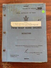
Manual (item) - (SP) AAP 7110.001-99 Pratt & Whitney Twin Wasp R1830 Manual
Parts catalogue for Pratt and Whitney R-1830-C3G and -92 engines. -
 Tatura Irrigation & Wartime Camps Museum
Newspaper article, Tatura Steam Engine, 2002
Newspaper article on the traction engine originally set up in Apex Park.Tatura Guardian article 09.04.2002 -
 Stawell Historical Society Inc
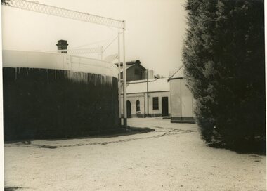
Photograph, Stawell Gas Works -- 19,000c. ft. Holder with Engine Room
Gas Company – Stawell 19000c.ft. Holder with Engine Room in centre background.stawell -
 City of Ballarat Libraries
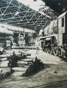
Photograph - Card Box Photographs, Inside the Locomotive Dept, Ballarat East 1960
The engines that can be seen are R769, R756 and R712. From the ARHS archives.locomotive, train, vehicle, ballarat east, transport, arhs -
Moorabbin Air Museum
Booklet (Item) - Correspondence Between Ansett and Malaysia Airlines Concerning Engineering Contracts, Ansett Engineering Resources
Correspondence relates to negotiation of engine repair contracts for aircraft such as the Fokker 50 -
 Stawell Historical Society Inc
Photograph, Engine & Plaque Photos at the Kay Foundry -- 3 Photos
Three colour photographs Two of an Engine one of a Plaque Kay Foundrystawell businesses -
Moorabbin Air Museum
Machine - SNECMA ATAR 13,000 Lbs Of Thrust Turbo Jet
Historical Details: . Description: The Atar jet engine was designed and built in France and was developed from the wartime German BMW 109 003 engine. It powered a number of aircraft types, the most notable of which was the Dassault Mirage. The Atar was built in Australia by the Commonw. Level of Importance: State -
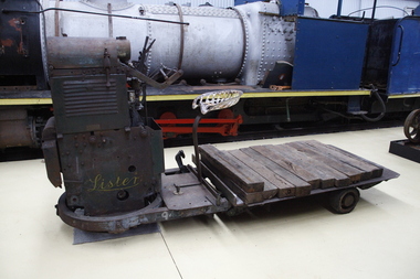 Puffing Billy Railway
Lister Auto Truck
The Lister Auto-Truck was a small monowheel tractor built for moving light loads around factories, railway yards and similar sites. They were built by R A Lister and Company of Dursley, Gloucestershire, well known for their range of small stationary engines The Auto-Truck was one of several monowheel tractors to appear in the 1920s and '30s, with the availability of small, reliable petrol engines, as developed for motorcycles and the stationary engines for which Lister were already known. These were tricycle vehicles, with the single leading wheel used for both drive and steering. Their simple construction carried most of the mechanism on this wheel as a single unit, the chassis with the trailing wheels being little more than a trailer for balance. Simplicity was a key feature. The engines were single-cylinder and air-cooled. Ignition was by magneto, rather than requiring a battery and electrical system. One of these designs was produced in the 1920s by George Grist of the Auto Mower Co., Norton St Philip, Somerset. The engine was a JAP 600 cc four-stroke air-cooled sidevalve, a typical small engine of the time. The Auto Mower Co. were Lister agents and when Lister heard of this 'Auto-Truck' they bought one for use in their own factory. It was used to carry heavy engine castings from the foundry to the machine shop. Lister customers saw them and there was such interest in wanting to buy them that Lister negotiated with Auto Mower to build them under licence. Although Lister were already well known for their small petrol stationary engines, these were heavy cast-iron engines with water hopper cooling and unsuitable for vehicle use. Lister remained with the JAP engine for the Auto-Truck. The Auto-Truck was designed for use in factories or other places with smooth surfaces of concrete or tarmac. This allowed the use of small solid-tyred wheels with only simple suspension, making the vehicle simple, cheap and lightweight. They had little ability on soft surfaces though and could even topple over if driven carelessly across slopes. Their design was a compromise between the top-heavy nature of the tall engine grouping above its wheel and a well thought-out chassis for stability. The bearing between them was a large diameter ring roller bearing, mounted at the lowest part of the chassis. This gave rigidity and stability, even after long wear. A ring of rolled channel girder was attached to the engine group and rollers on the chassis carried the load upon this. On early Auto-Trucks this bearing is set very low, in line with the chassis members, and is covered by thin steel plates. The front panel of the engine cover is distinctive with large ventilation holes and a Lister signature cut through it. Strangely this panel is made of thick cast iron, providing substantial weight high on the engine and only adding to its top heaviness. To improve visibility of moving vehicles in noisy factories, this panel was often painted white, the rest of the vehicle being Lister's usual brunswick green. The driver was seated on a Brooks bicycle saddle, which in recognition of the lack of vehicle suspension, was carried on the end of a cantilevered bar that acted as a leaf spring. A wide handlebar on the engine group was used for steering. A squeeze bar the width of this handlebar engaged the clutch. Controls included a hand throttle, a gear lever with two forward and one reverse gears, and a large handbrake lever. The engine unit rotated freely for a full 360° rotation. When used in reverse, the Auto-Truck could either be driven from the saddle, looking backwards over the driver's shoulder; or they could dismount, swivel the engine unit around and control it as a pedestrian-controlled truck from behind. Under the engine cover were two equal diameter tanks, a fuel tank for petrol and a shorter oil tank. Engine and chain-drive lubrication used a total-loss oil system, controlled by a small pump and needle valve. Info Ref: Lister Auto-Truck - Wikipedia https://en.wikipedia.org/wiki/Lister_Auto-TruckHistoric - Industrial monowheel tractor for moving light loads around factories, railway yards and similar sites.The Lister Auto-Truck - small monowheel tractor Made of steel with three wheels. Powered by a J.A.P single cylinder petrol motor which is Hand Cranked to start.Lister puffing billy, lister, lister auto truck, monowheel tractor -
Moorabbin Air Museum
Machine - Bristol Hercules 672 - 1700 HP Air Cooled Twin Row 18 Cyl
Historical Details: . Description: Developed in Britain in 1938 the Bristol Hercules sleeve valve 18 cylinder twin row air cooled radial engine was one of the most powerful British aero engines of the day. It powered the Beaufighter and Bristol Freighter amongst other aircraft.. Level of Importance: s/n 167516