Showing 497 items
matching switchable
-
 Lara RSL Sub Branch
World War 2 War Graves of Lara Men, Photograph of Head Stone of grave site Pte. A. Bowler at Bomana War Cementary, New Guinea and Grave Site of Flight Lieutenant J.S. Austin DFC grave site Adelaide River, N. T
Flt Lt J S Austin DFC, 400363. No 608 Sqn RAF, Nos 32, 13 & 2 Sqns. Stock agent of Lara, Vic; b Melbourne 15 May 1918. Died of illness 9 Nov 1943. Timor was the target for the night of 6 July, when Flight Lieutenant "Bunny" Austin (A16-207) led five Hudsons to bomb Koepang town. The next night he led back seven aircraft against the airfield at Penfoei, attacking before dawn on the 8th prior to United States Liberators bombing the runways and barracks. 75 Austin's aircraft was caught by Penfoei's master defensive searchlight, and Austin used violent evasion and switching on and off of his IFF equipment, a tactic used in Europe. The radar-controlled searchlights went out. Flying Officer Mick Helsham (A16-160) attacked first to act as a pathfinder and mark the target for the other Hudsons and Liberators:Full service records of J. S. Austin held by Lara R.S.L.Plain Sheet A4 paper with 2 photographs 1. A. Bowler W. 9.8 cm H. 13.8 cm photograph 2. J.S. Austin W. 1`5.9 cm H. 10.0 cmA4 sheet heading as: W.W. 2 War Graves of Lara Men. Note on photograph 1. Grave of A. Bowler, Bomana War Cemetery.r.a.f., graves, lara -
 Ballarat Tramway Museum
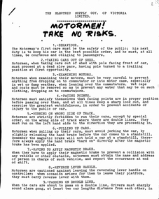
Document - Instruction, B. Prentice, Motormen! Take No Risks", Jun. 1947
Yields information about the instructions issued to Motormen in Ballarat by the Electric Supply Co. for driving and operating tramcars.Instruction - 6 quarto sheets stapled in top left hand corner - retyped from an original Electric Supply Co. of Victoria (ESCo) document with a black hand written heading Motormen! Take No Risks", detailing motormen's behaviours, operations, braking, tram car lights, steps, ticketing, recruit motormen, shunting, speed, trolley wheels, changing cars, trailers, controllers, testing magnetic brakes, switches, timetables, fares, tram stops, section staffs, holidays, uniforms, breakdowns, smoking, lost property, headways, gong signals, conductors, whistle signals, instructions to recruit motormen. 7th page - details motors and how to get your car ready for service and how to apply power. (see btm8096i1.pdf) page 8 missing. trams, tramways, esco, training, instructions, motormen, operations -
 Ballarat Tramway Museum
Photograph - Black & White Photograph/s, mid to Late 1965
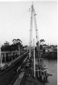
Set of two Black and white photographs of the pile driving for the reconstruction of the Maribyrnong River Bridge from a tramway only bridge to a dual road/tram bridge. The road bridge is in the background. On Kodak paper. Photo during the 2nd half of 1965. 1419.1 - Early in the process of pile driving - Bridge tram track has been reduced to single track and the former outbound line is in use for construction purposes. 1419.2 - Roadway west of bridge looking east. Shows temporary single track arrangement which allowed the operating track to switch to the south side when piling completed. W5 682 West Maribyrnong on route 57 coming off the bridge. See P.Winspur note - and Rail News Victoria May 2000, page 50. Features a photograph of a tour on the bridge on 1/10/1966.trams, tramways, maribyrnong river bridge, bridge construction, trackwork, mmtb, tram 682 -
 Ballarat Tramway Museum
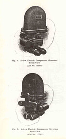
Manual, Melbourne and Metropolitan Tramways Board (MMTB), "Notes on Westinghouse S6-A and S6-B Compressor Governors", c1980
Nine Page photocopy of a Westinghouse manual for Westinghouse S6-A and S6-B Compressor Governors (often known as Beatle Back type). Includes cross sectional diagrams of both compressors, photographs, connection diagrams, and detailed descriptions. The descriptions include notes on the compressor, switch portion, regulating portion of the device, regulation and adjustments, setting of cutouts, installation and maintenance. Originally prepared by Westinghouse, Wilmarding PA, USA, 20/9/1916. Retyped by MMTB 5/1955 and provided to Warren Doubleday from Preston Workshops c1980. Copy contained within a stapled and bound manila folder with handwritten title on outside. 2nd copy added 9-6-2019 from the Melbourne Tram Museum - in a manila folder with a black binding. Copy of above document. See pdf file for full scan.trams, tramways, air compressors, westinghouse, maintenance, dh16b, governors -
 Ballarat Tramway Museum
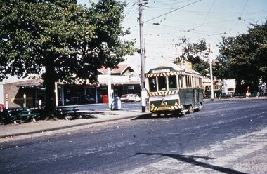
Slide - 35mm slide/s, late 1960's
Agfa plastic mount (blue base, white cover) of a photograph of No. 43 turning from Drummond St South into Sturt St at Hospital corner. Has the shops on the south west corner in the background. Photo taken late 1960's. Tramcar has an SEC roof advertisement. Note the ESCo electrical switch/junction box in the photograph, to the left of the tram. A single truck tram is in the background and the short stubby tram stop pole in Drummond St. South. The slide appears to be a copy slide, given the nature of the colour and the additional number WP415. Photographer could be Bill Pearce (WP). Slide rescanned at 3200 dpi 25-10-2020, jpg replaced, tiff file retained. This file was scanned in 2003 and may show colour changes."BAS 55 in penciltramways, trams, hospital corner, drummond st, sturt st, tram 43 -
 Ballarat Tramway Museum
Photograph - B&W print of donated negative, John Webster, 21/08/1955 12:00:00 AM
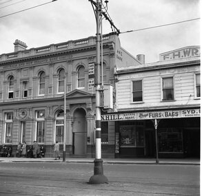
Yields information about the appearance of the appearance of the SEC tram stop equipment at the corner of Ryrie and Moorabool StreetsBlack and white digital print from scan of a donated negative showing the signage at the tram stop in Ryrie St at the corner of Ryrie and Moorabool Streets Geelong. Shows the End of Section, pole banding, Cars Stop Here Sign and a section isolator switch box. Has the Australian and New Zealand Bank Limited, L. N. Hill Estate Agent, Wrays Furs and Bags and F.H.Wray Building in the background. Alongside the ANZ bank building is a number of potential passengers, ladies and gents in overcoats. Assumed photo taken on the same day as the others - 21-8-1955. Black and White prints made from scan of negative. Original Negative stored with Negatives. Negative scanned at hi res 4/6/2020 and image updated.On left hand side of the negatives in ink is "DB12"tramways, trams, geelong, tram stops, moorabool st, ryrie st -
 Ballarat Tramway Museum
Document - Instruction, State Electricity Commission of Victoria (SECV), "Forest City Signals", late 1960's?
Yields information about the instructions about Signalling system on Wendouree Parade and Bridge St - Forest City signals.Five page, foolscap duplicated document, stapled in the top left hand corner, titled Forest City Signals, undated, has letters S4 in top right hand corner of first sheet, giving details about the Forest City signalling system installed in Ballarat, particularly around Wendouree Parade and the depot. Explains how the system operates, gives instructions, details of the system, location of the loops, trams following each other, power failure. Also gives details of how the Bridge St system operated and the switch at Grenville St. Note: The locations of the signals may not be not as detailed as in the Driver Training Manual - See Reg Item 3486. Does not provide instructions for Lydiard St North or Sebastopol routes. See also Reg Item 3456 for another similar copy.trams, tramways, signals, crossing loop, forest city signals, grenville st, wendouree parade -
 Ballarat Tramway Museum
Drawing - Brisbane City Council Tramway Trackwork drawings
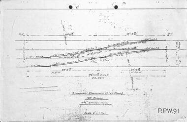
Prepared by the City of Brisbane for the design of trackworkYields information on the design of trackwork.Set of nine City of Brisbane Tram Track drawings .1 - PPW91 - Standard Crossover left hand - 4'6" between tracks .2 - PPW2450 - Data for British Standard Crossings .3 - PPW 241 - Data for British Standard Lateral Switches .4 - PPW 463 - Concrete Track Construction is 102.73lb rail. .5 - PPW 501 - ditto for AS 82lb rail and other rails .6 - Not numbered - Concrete roads when using T rail sleepers .7 - PPW 575 - 150' radius RH crossover - 5' between tracks .8 - PPW 576 - 150' radius RH Crossover - 4'6" between tracks .9 - PPW 577 - 150' radius LH Crossover - 5' between tracks - 14/12/1948trackwork, points, switches, bcc transport, tramways -
 Kiewa Valley Historical Society
Timer Mechanical, Circa 1950
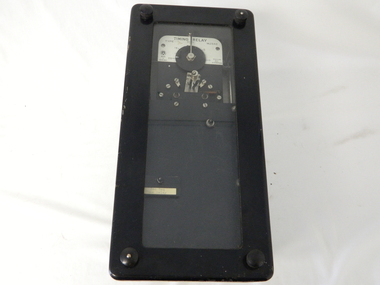
This Timing Relay is quite a large (industrial type) apparatus. The Timer is started by having a voltage of 250 volts direct current (as supplied by batteries). A DC motor then rotates driving into a clockwork mechanism, the output of which is an arm rotating at the same speed as a minute hand on a clock. Attached to this arm is a mercury switch which tips and makes an electrical circuit operate in a sequence control system. The sequences that use these timers are when starting and stopping Hydro Generators. They check that the machine has connected to the power system grid before 20 minutes duration. Brakes must go on for a set time when shutting down a generator slowing at the right speed as measured by this apparatus. These generators are powered by the hydro force of "stored" water at a higher altitude. The establishment of both the NSW and Victorian Hydro schemes was achieved from the mid 1900's to the 1960's. At this point in time the need for additional power sources to quench both an industrial and domestic demand for electricity was purely an economic and not and environmental (carbon reduction) factor. This Timing Relay apparatus is very significant to the Kiewa Valley as its use was introduced during the Kiewa Hydro Scheme. Although only a relay apparatus, it was however part of the explosion of human resources into the valley. This influx of population transformed the region from that of a basically quiet rural region to one which evolved into both an industrial and a larger residential community. This evolution in the valley created a change, not only in the "physical" landscape but also the socio-economic expansion which permitted other "tourist" based industries into the valley. This Hydro Scheme was instigated by "the Government of the day" as a bold move and was the major force behind the acceptance of World War II refugee and "technical" workforce. Inclusion of skilled and unskilled migration into the Australian environment was of a higher priority than a selective quota system of later years.. Although this mass "invasion" of workers with families was thought of in some circles as intrusive, the expansion of population post war years and its integration into the Australian rural sector, produced the multi- lingual, multi-cultural diversity of later years.sec vic kiewa hydro scheme, alternate energy supplies, alpine population growth -
 Bendigo Military Museum
Programme - CENOTAPH DEDICATION 1988, C. April 1988
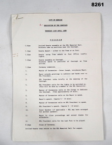
This is the seventh in a series beginning with Cat No 8255 showing the progress towards the Restoration of the Bendigo Cenotaph over the Bendigo Creek. Page 1 gives a timeline of the evening beginning at 7.00pm with guests preparing to move to the Cenotaph, Ceremony beginning at 7.30pm through to close at 8.30pm and then guests returning to the RSL Memorial Hall for Supper. Page 2 is as per "Inscriptions & markings. Page 3 is a listing of happenings, Master of ceremonies - Mr Peter Joseph. Greeting by Mayor Cr. Colin Nankervis, The meaning of the Cenotaph - RSL President, Switching on the lights, Dedication of the Cenotaph, His Worship the Mayor Cr Colin Nankervis, Mr max O' Haloran RSL President. Last Post. Pages 4 - 5 are the Prayers & Readings, Prayers of Remembrance, Lords Prayer given by the following Churches. Rev. Canon A.G. Austin (Anglican) R.L. Faulkner (Uniting), Capt P. Wright (Salvation Army), Rev I. Porter (President Ministers Fraternal) Fr. T. Pearson O.F.M (Catholic)Program, 5 pages, white paper, all text in black print, stapled together top LH corner.Main point, "City of Bendigo - Dedication of the Cenotaph - Thursday 21st April 1988".brsl, smirsl, cenotaph, bendigo -
 Ballarat Tramway Museum
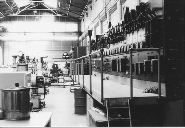
Photograph - Black & White Photograph/s - set of 4, Richard Gilbert, 20/08/1971 12:00:00 AM
Set of four black and white photographs of interior and equipment of the former ESCo / SECV Wendouree Parade Ballarat A power station sent to the Editor of Trolley Wire - used in the November 1997 issue of Trolley Wire. All photos by Richard Gilbert. Photos taken on 20/8/1971. All photos on Kodak paper. 1144.1 - Looking along building at main distribution switch panel - used on page 24 of trolley wire. 1144.2 - a view across the main steam generator section of the power station - and AC plant - used on page 23. 1144.3 - of the British Thomson Houston rotary converters in used at the time of the photo - used on page 23. 1144.4 - a view from the opposite end of the building shown in 1144.1 - showing the rotary converters are in the front of the photo, AC generators in the middle and foreman's cabin - used on page 22. All have yellow stickers with photo number for magazine printer, and white sticky labels with photo number and words "photo xx same size" written on black ink and photo numbers in pencil from Richard.trams, tramways, trolley wire, esco, power station, ballarat a power station, rotary converters -
 Ballarat Tramway Museum
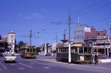
Slide - 35mm slide/s - set of 3, Noel Simons, 22/11/1962 12:00:00 AM
Set of 3 transparencies taken on 22/11/1962 on Kodak mounts. 1190.1 - No. 7 (bound for North Bendigo) at the Charing Cross stop with No. 19 just left for Quarry Hill. Has the buildings on the south side of High St. in the background, including RACV building. No. 7 has front dash panel ad for Streets ice cream, and roof ads for Ilford Film and an SEC "Cook with Electricity". Passengers are boarding the tram. 1190.2 - Bendigo No. 2 at Charing Cross with fountain in the background and other buildings on the south side of High St. Tram has two SEC roof ads - good side on view - "Electric Cooking - Matchless" and "Switch to Electric Cooking". 1190.3 - Nos. 19, 2 and 7 at Charing cross with a Austin ? motor car. Has buildings on the south side of High St. in the background, along with SEC and Ilford film roof ads.Information written on in black ink and date stamped on purple ink. 1190.1 - "Nos. 19 and 7 at Alexandra Fountain, Charing Cross, Bendigo" 1190.2 - "No. 2 at Alexandra Fountain, Charing Cross, Bendigo" 1190.3 - "Nos. 19, 2 and 7 at Alexandra Fountain, Charing Cross, Bendigo" tramways, trams, bendigo, charing cross, alexandra fountain, tram 2, tram 7, tram 19 -
 Ballarat Tramway Museum
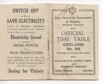
Ephemera - Timetable, "Official Timetable Geelong No. 39", 1943
Printed, single stapled 8 sheets folded and titled SECV "Official Timetable Geelong No. 45", 16 image files - 32 pages, giving details of the fares, transfers, luggage or parcels, lost property, times of each tram on the Newtown, West Geelong, East Geelong, Chilwell, Eastern Park, Belmont,, North, . Gives details of fares, luggage, lost property. On rear has an SECV Advert to "Switch Off to Save Electricity - Saving for Victory" Timetable undated, probably c1943 - see Reg Item 5633 for date forwarded to Wal Jack from Geelong SECV office - was the then current timetable. See also Reg Item 5357 for Timetable No. 45, c1949 and 8552 for a photocopy of No. 47, March 1953 and 9821 for a photocopy of No. 46 Contained originally within Reg Item 5623 at the front of this note book. For items see btm5623 loose items list.pdfgeelong, timetables -
 Geoffrey Kaye Museum of Anaesthetic History
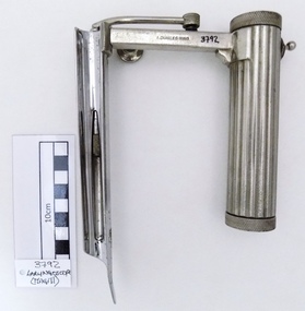
Tool - Laryngoscope, Magill, 1926
Ivan Magill (1888-1986) designer, this piece was designed in 1926 along with other anaesthetic equipment.Chrome plated straight complete Magill laryngoscope in medium size format, with attached light bulb. Cylindrical handle for battery deposit and with a wavy hand grip for easy handling. Serrated and screwed lids on top and base of the handle grip for insertion of batteries and checking of electrical contact stud. The handle also has a metallic switch without any instruction of use. The arm of the handle has a detachable screw to adjust extendable blade position and firmness. The light bulb is attached to a metallic tube connector to the handle arm which is just pressed to the contact point base. The blade has a oxidation spot under the blade. The piece in full has several scratches marks mostly founded in handle, arm and top blade areas. Two stamped inscriptions are present on the arm area, the manufacturer name and register number.Stamped on the arm of the handle lateral side, A.CHARLES KING Stamped on the arm of the handle opposite lateral side, REG. NO. 74901[9]magill, a. charles king ltd, regi. no. 749019, switch, laryngoscope -
 Flagstaff Hill Maritime Museum and Village
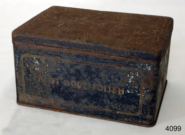
Container - Tin, Kiwi Shoe Polish Manufacture, 1940s
The polish was developed in Australia by William Ramsay who named it Kiwi after the flightless bird endemic to New Zealand, the home country of his wife, Annie Elizabeth Meek Ramsay. Its success in Australia expanded overseas when it was adopted by both the British and American armies in World War I. In the UK, Kiwi was for many years manufactured at its British headquarters in Ealing (Brumwell Road, London W5 1DT). From here the factory manufactured for the UK market and exported the Kiwi brand too much of Europe and the Middle East. In the mid-1970s, as part of a major streamlining, the UK factory was closed with production switched to France. The UK operation moved to Surrey at Yately becoming, effectively, a sales and marketing office, with distribution contracted to a third party. In 1980, production for the UK market moved back to the UK and was housed in a factory near Huddersfield. The UK head office was relocated to Maidstone, Kent, where Kiwi had other product interests. Following the global merger with Nicholas Laboratories, the UK head office was again relocated to Slough at the Nicholas building on Bath Road.A significant product as Kiwi is an Australian brand name of shoe polish, first launched and sold in Australia in 1906 and as of 2005 sold in almost 180 countries. Previously owned by the Sara Lee Corporation since 1984, it was sold in 2011 to S. C. Johnson. It is the dominant shoe polish in some countries, including the United Kingdom and the United States, where it has about two thirds of the market. In Malaysia and Singapore, Kiwi has become such a household brand for a shoe polish that the word "kiwi" has been genericized into a verb in the Malay language, meaning "to polish one's shoes".Metal cleaning outfit of Kiwi boot polish brush, scraper, & polish missingKiwi Boot Polish to front of containerflagstaff hill, warrnambool, shipwrecked-coast, flagstaff-hill, flagstaff-hill-maritime-museum, maritime-museum, shipwreck-coast, flagstaff-hill-maritime-village -
 Flagstaff Hill Maritime Museum and Village
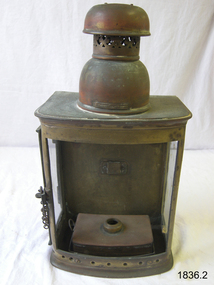
Functional object - Marine Lamp, William W M Mc Geoch Ltd, 1910 to 1925
In 1832 William McGeoch & Co., Ltd was established, by William McGeoch senior at 113 Argyle St Glasgow as hardware merchants and exporters, and later were manufacturers of lamps and electrical fittings for ship, railway and domestic use. In the 1900s the company had expanded and had offices at 28 West Campbell Street Glasgow with a factory and warehouse located at the Warwick Works, 46 Coventry Rd, Birmingham. In 1922 the company had expanded and were employing 400 to 500 people. William seniors three sons had joined their father in establishing the business around 1888. The business was run by William McGeoch senior with Williams three sons Alexander, William and Andrew also taking an active part in the day to day running of the company. The company had expanded to such a degree that they were now manufacturing a variety of ships' hardware. This included metal cabin furnishings, signal lamps, ships' oil and candle lamps, motor lamps, switches, switchboards, electrical accessories and fittings. In 1982 William McGeoch & Co., Ltd was acquired by Bowthorpe Holdings Ltd.A lamp made by a significant manufacturer of marine equipment that made fittings for many famous ships including the Titanic.Marine oil Lamp with glass panels. Front panel missing. Access through glass panel door at side flat metal back. Metal fuel reservoir and no burner. Metal rounded chimney on top. Embossed McGeogh Maker Glasgowwarrnambool, flagstaff-hill, flagstaff-hill-maritime-museum, maritime-museum, shipwreck-coast, flagstaff-hill-maritime-village, lamp, ships lamp, wm mc geoch ltd, hardware merchants, ships outfitters -
 Vision Australia
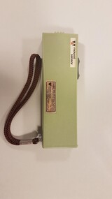
Equipment - Object, Wormald International Sensory Aids Ltd, Mowat sensor, 197
The Mowat Sensor model MS 01, is a pale green, palm-sized, plastic battery-operated device with a darker green switch on top. It is partially open at one end with two grilles. A microphone plugs into the other end with a wrist strap. It came with a brown vinyl carry case and owner's manual, which are not included. This handheld device for the visually impaired uses high frequency sound to detect objects within a narrow beam. The sensor vibrates if an object is present, responds to closest object within the beam. The vibration rate increases as user approaches object. There are two range settings: short, responds to objects less than 1 meter away (indoor use) and long, responds to objects of sufficient size up to 4 meters. The sensor can be handheld or carried in pocket or purse. As a facility intended for partially sighted people, the compass also includes an in-built color indicator (visible through the semi-transparent enclosure), which indicates the direction using a combination of three colours. Weight: 185 grams. Comes with dark brown vinyl case.1 pale green coloured plastic rectangle sensor with a brown nylon, plaited wrist strap Model MS01assistive devices, orientation and mobility -
 Wodonga & District Historical Society Inc
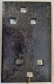
Functional object - Rail fish plate from Cudgewa Line, 1930 - 1960s
Cudgewa Line -The Cudgewa railway line opened in stages between 1889 and 1921. The first section from Wodonga to Huon opened on 10 September 1889. It was extended to Bolga on 18 July 1890, Tallangatta on 24 July 1891, Shelley on 13 June 1916 (the highest station in Victoria), Beetomba on 10 April 1919 and Cudgewa on 5 May 1921. The line had 1 in 30 grades and trestle bridges that have been heritage listed. In 1919, the line was used to carry materials for the construction of Hume Weir, and three years later a spur line connecting Ebden to the weir was opened. In the 1960s, Cudgewa became the railhead of materials for the Snowy Mountains Scheme. The last passenger service from Wodonga to Tallangatta ran on 30 September 1961. The turntable and passenger platform at Cudgewa were abolished in 1976. This fish plate came from the rails of the Cudgewa Line at Gordon Roy's hut which was situated behind Perry's Stump Hotel outside Wodonga. The hut was used as an office with the points lever outside to switch trucks to different tracks on the Bandiana and Cudgewa lines.This item is significant as it was part of the railway line to Cudgewa which played an important role in North east Victoria carrying freight during the construction of the Hume Weir and the Snowy Mountains Scheme.A section of flat plate. These plates were used in pairs to connect the ends of adjacent rails in railway track. victorian railways, cudgewa rail line, railway components -
 Wodonga & District Historical Society Inc
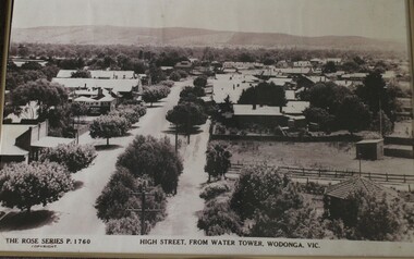
Photograph - High Street Wodonga, Rose Series, Rose Series, c1930-1940
This photograph, enlarged from a post card from the Rose Series, is representative of many images representing High Street, Wodonga as it developed over time. The Rose Series of postcards is a series of postcards of scenes from around Australia and some international ones as well. They were produced by the Rose Stereograph Company, which was the business of Victorian photographer George Rose (1861-1942). In 1880, George, aged 19, founded his business in Victoria, and soon became famous for producing stereographs, or stereo views. His early images included the landing at Anzac Cove, Ned and Dan Kelly’s Armour (taken at trial in 1880), The Duke & Duchess of York and their daughter Princess Elizabeth and Phar Lap winning the Melbourne Cup. When stereographs lost popularity during the 1920s, Rose switched to the production of postcards and decorative cards. He and his team of photographers took thousands of photos of scenery around Victoria and beyond, and the postcards became iconic images of Australian life. The Rose Stereograph Company Collection comprising more than 100,000 items was auctioned by Lloyds in June 2021.This is an image from an important collection of postcards which were representative of towns in Victoria taken c1920 - 1940sThis is an enlarged black and white photo of a postcard of High Street Wodonga from the Rose Series Across bottom of photo "THE ROSE SERIES P.1760 HIGH STREET, WATER TOWER, WODONGA, VIC."rose series p.1760, wodonga post cards, high street wodonga -
 Forests Commission Retired Personnel Association (FCRPA)
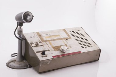
Base station radio with handset, Mid 1980s
After the 1939 bushfires, the Forests Commission invested heavily in a radically new communications network. After suffering some inevitable delays due to the War, radio VL3AA switched into full operation in October 1945 proudly beaming out 200 watts across the State. But by today’s standards, the technology was primitive and the reception poor unless the user was on a high point somewhere. The radio signal was "line-of-sight" and bounced between fire towers and relay transmitters across the mountains back to the District offices. The more secure and versatile State Mobile Radio (SMR) digital trunk system came into operation in about 1995. Upgraded Tait Radios were purchased in 2014 after recommendations of the 2009 Bushfires Royal Commission. But it was the convergence of separate technologies such as 4G mobile phones, high-capacity and light-weight lithium batteries, Wi-Fi, the ever-expanding internet, cloud data storage, digital cameras, GPS, personal organisers and hundreds of supporting Apps into powerful smartphones and tablets which revolutionised bushfire communications from the mid-2000s.Base station radio with handsetRC-4B Amalgamated Wireless Australiabushfire, radios, forests commission victoria (fcv) -
 Eltham District Historical Society Inc
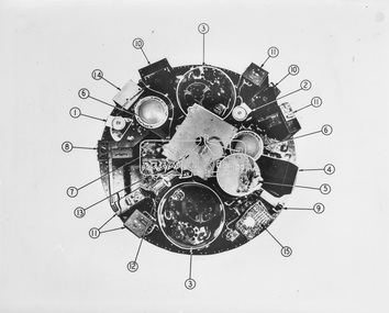
Photograph - Black and White Print, NASA, Tiros II - Taken from above with cover removed, 1960
On reverse: Tiros II - Taken from above with cover removed: 1. Wide angle TV camera 2. Narrow angle TV camera 3. TV tape recorders 4. Infra red - 5 channel radiometer 5. Infra red electronics 6. Electronic operations sequence timing 7. Relays for magnetic stabilisation for altitude 8. Control box for electronics 9. Infra red horizon scanner 10. Electronic camera circuits 11. Electronic TV tape circuits 12. Telemetry switches 13. Antenna diplexer (covering storage batteries) 14. Automatic signal generator 15. Fuse board and current regulatoralan gardiner collection, space industry, 1960, satellite, tiros ii -
 4th/19th Prince of Wales's Light Horse Regiment Unit History Room
Training Set, Universal, Wireless, No 1, about 1948
The kit is packed in 2 wooden transit boxes. The Training Set is a semi-portable instrument for training operators in morse reading and sending and R.T. communication. The set comprises audio oscillators for morse reading, morse interference and background noise interference, power supply for microphones, an audio amplifier, and a switch board for group working with up to six independent, contained in the instructor's set. The instructor and each operator under training has a receiver-head gear, a hand microphone and a morse key. The instructor has an additional morse key used for providing morse interference. In the case of each operator, the microphones and headphones plug into an "operator's control unit" fitted to the table in front of each operator. The units also house a morse key, and are connected to the instructor's set by four-core cable. Plug and socket connections are used. The apparatus may be used for a class of up to 36 operators. Working Instructions - filed on Object Data Record radio, wireless, training set -
 Ballarat Tramway Museum
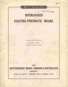
Document - Technical pamphlet/s, Westinghouse Brake Company of Australasia Limited and The Westinghouse Brake & Saxby Signal Co. Ltd. of 82 York Road and Kings Cross London, "The Westinghouse Brake with Electro-Pneumatic Control", Dec. 1926
2285.1 - 12 page technical pamphlet (2 sheets of paper - pages 5 -10 formed as a concertina folded centre sheet) titled "Interlocked electo-pneumatic brake", published by Westinghouse Brake Company of Australasia Limited, December 1926. Manual D.P. 9. Stapled with two steel staples along fold. Describes in detail the electro-pneumatic brake system as used on Sydney Suburban trains, complete with diagrams, brake valve operation, magnet valve and isolating cock switch. 2285.2 - Six page technical pamphlet, titled "The Westinghouse Brake with electro-pneumatic control", published by Westinghouse Brake and Saxby Signal Co. 1915. Pages 3 and 4 have been tipped in the cover sheet. Describes standard brake equipment for use with electric trains and electro pneumatic control over the brakes. Gives details of house the brake valve (No. 18 EP) operates. Scanned to the COTMA Website 4-10-2015."Colin Rutledge" stamped on top of page 1.trams, tramways, westinghouse, electric trains, electro - pneumatic brakes, sydney suburban trains -
 Ballarat Tramway Museum
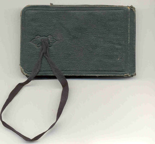
Ephemera, The Commercial Notebook, Ballarat tram timetables, 1913
Notebook, green cloth covered, with end papers, five sections ruled sheets sewn fitted with a black cotton tape strap. On side of notebook, in the same cloth, a holder for a short pencil has been provided. On inside end paper, has a sticker of the "The Commercial Notebook", discount table. In pencil is "J.H. Prisk / 516 Drummond / Ballarat" On first pages inside are details of change float, tickets sold, type , returns commencing "Monday 15/12" (1913) through to March 10 (1914), then many pages with monetary calculations, then sketches of tramcar lighting circuits, noes on cabling, roses, switches, current densities, and conduits lengths etc. Last page in notebook has notes re times of cards ex Sheds and Sebastopol and working hours on various runs. See worksheets in Reg. Item 3140 for details about Jack and his SEC driving career.On back of photograph in black ink "Jack Prisk Sec. Driver & Daughter Marg."trams, tramways, sec, drivers, esco, crews -
 Ballarat Tramway Museum
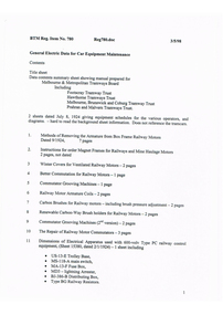
Manual, Doug Prosser, "General Electric Data for Car Equipment Maintenance", 1998
A black plastic folder containing a set of 38 General Electric Data Sheets for MMTB and tramway trust equipment, dated July 8 1924. Contained in folder with flexible clips. Pages have been punched with four holes. Copy of document made for BTM Feb 1998 by Doug Prosser. For scan of list - see btm780sheet.pdf General Electric Data for Car Equipment Maintenance Contents For scan see btm780d1 (5 pages) Title sheet Data contents summary sheet showing manual prepared for Melbourne & Metropolitan Tramways Board Including Footscray Tramway Trust Hawthorne Tramways Trust Melbourne, Brunswick and Coburg Tramway Trust Prahran and Malvern Tramways Trust. 2 sheets dated July 8, 1924 giving equipment schedules for the various operators, and diagrams. - hard to read the background sheet information. Does not reference the tramcars. For scan see btm780d2 (54 sheets - items 1 to 27) 1. Methods of Removing the Armature from Box Frame Railway Motors Dated 9/1924, 7 pages 2. Instructions for order Magnet Frames for Railways and Mine Haulage Motors 2 pages, not dated 3 Winter Covers for Ventilated Railway Motors - 2 pages 4 Better Commutation for Railway Motors - 1 page 5 Commutator Grooving Machines - 1 page 6 Railway Motor Armature Coils - 2 pages 7 Carbon Brushes for Railway motors - including brush pressure adjustment - 2 pages 8 Renewable Carbon-Way Brush holders for Railway Motors - 2 pages 9 Commutator Grooving Machines (2nd version) - 2 pages 10 The Repair of Railway Motor Commutators - 3 pages 11 Dimensions of Electrical Apparatus used with 600-volv Type PC railway control equipment, (Sheet 15380, dated 2/1/1924) - 1 sheet including · US-13-E Trolley Base, · MS-118-A main switch, · MA-13-F Fuse Box, · MD3 - lightning Arrester, · BJ-386-B Distributing Box, · Type BG Railway Resistors. 12 Connections of Type KM-63-BR Railway Controllers and Equipment - Drawing 15257, 1 page, dated 1/3/1921 with dimension details on rear of type K-63-BR railway controller equipment including: · SG Resister, · BK-13-A Insulator, · MR11 - Circuit breaker, · MD3 - Lightning Arrester box, · K63-BR Controller, · US15C Trolley Base. 13 Method of Supporting Railway Resistors using Porcelain Bolt insulators for 600 and 1500 Volt Work. Drawing dated 1/11/1923, No. 15249B - 1 page 14 Dimensions of Electrical Apparatus used with 600-volv Type M railway control equipment, (Sheet 15381, dated 2/1/1924) - 1 sheet including · US-13-E Trolley Base, · MS-118-A main switch, · MA-13-F Fuse Box, · MD3 - lightning Arrester, · BJ-386-B Distributing Box, · Type BG Railway Resistors. 15 Dimensions of Electrical Apparatus used with 600Volt, Type PC Railway Control Equipment. Drawing No. 15382, dated 2/1/1924. Includes: · C129-A Master Controller, · DA82C Coupler sockets, · MS-14-G switch, · MS-46-H switch. 16 Dimensions of Electrical Apparatus used with 600-volv Type M railway control equipment, (Sheet 15383, dated 2/1/1924) - 1 sheet including · C-169-A Controller · DA-69-B Coupler Socket and DC-66-C Coupler Plug · MS-14-G Switch · MS-46-H-Switch 17 Method of Making Tap Connections for Car Cables -= SD 15468, 1/11/1924, 1 page 18 The Repair of 600 Volt Railway Motor Armatures, 64408, 9/2/1924, 4 pages 19 Proper Method of Mounting and Dismounting Railway Motor Pinions. - 2 pages 20 Pinion Pullers for Railway Motors - 2 pages, dated 8/1/1924. 21 The Care of Railway Motor Bearings - 4 pages 22 Oil Scraper Rings for Air Compressors - 64590 - May 1924 - 1 page 23 Finger Bases for type K 63 controller 1 page 24 Adjustment of Drum Controller fingers - 29/1/1924, 64600A - 1 page 25 Star Wheels for Type K Controllers - 64603 - 1 page 26 Soldering Aluminium Controller Cylinder Castings - 2 pages 27 Porcelain Bolt Insulators for Railway Service - and drawing on rear showing mounting arrangement of resistor Grids - 2 pages. For scan see btm780d3 (13 pages) 28 Connections of Armature and Field Winding for GE-201-F and GE 263A railway motors. DS37869 29 Connections of Armature and Field Winding for GE-201-I railway motors. K1629303 30 Connections of Armature and Field Winding for GE-202 motor, DS 10472 31 Connections of Armature and Field Winding for GE-203 A and GE 226 railway motors. DS23869. 32 Connections of Armature and Field Winding for GE-241 motors - K1629077 33 Connections of Armature and Field Winding for CP25A Air compressor 34 Connections of Armature and Field Winding for CP27A Air compressor 35 Connections of Armature and Field Winding for GE-258 and GE 264 railway motors. K1629343. 36A- Dimensions of Type K-63-BR Railway Controller Equipment 36 US-13-E Trolley Base for Railway Service - 3/1/1923, 64823 - 2 pages 37 Copy of M&MTB (Eastern System) Certificate of Competency as Motorman. 38 Photocopies of a series of four photos of 22E trucks under an SEC tramcar. For scan see btm780d4 (40 pages) 39 Sprague G-E Multiple Unit Control, Type PC, Instruction Book 84772 - Oct. 1922 - 40 Pages. Images of sheets added 2-11-15 trams, tramways, general electric, motors, controllers, trolley pole bases -
 Seaworks Maritime Museum
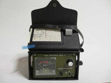
Gas Detector
1990 -24/04: To "Salvageman Ltd" at Douglas (IOM)One gas detector housed inside a black leather carry case, with a carry strap, and a pocket at back of carry case.1993 circa.on detector: "OMA-3/ON/OFF/ TYPE OMA-3/ KOMYO Paper card inserted in case, written with pen: "1) Turn on/off switch "ON"/ 2) Battery Check:/ Hold down smaller/ Button. Needle must be / within lower red scale/ 3 Zero Calibration Scale/ Press Larger Dial and Turn to Set Needle on/ Green on Lower Scale" handwritten on case: "PWO 3076" Sticker on case: "GASTECH/CALIBRATED/ Date 31-8-93/ Next Due/ 31-2-94/ Initials MW/ Serial no. 6479" Card attached by string, written in pencil: " PWO 3076/ Gas Detector/ Model no. 6479 [From the Howard Smith Collection]" -
 Forests Commission Retired Personnel Association (FCRPA)
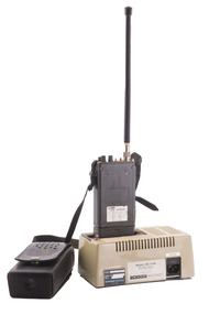
Portable UHF Radio - Sawtron / Kyodo, c 1980s
After the 1939 bushfires, the Forests Commission invested heavily in a radically new communications network. After suffering some inevitable delays due to the War, radio VL3AA switched into full operation in October 1945 proudly beaming out 200 watts across the State. But by today’s standards, the technology was primitive and the reception poor unless the user was on a high point somewhere. The radio signal was "line-of-sight" and bounced between fire towers and relay transmitters across the mountains back to the District offices. Rapid improvements in technology led to various models of bulky handheld portables with heavy batteries that always seemed to go flat. In fact, batteries were a constant impediment at bushfires. The more secure and versatile State Mobile Radio (SMR) digital trunk system came into operation in about 1995. Upgraded Tait Radios were purchased in 2014 after recommendations of the 2009 Bushfires Royal Commission. But it was the convergence of separate technologies such as 4G mobile phones, high-capacity and light-weight lithium batteries, Wi-Fi, the ever-expanding internet, cloud data storage, digital cameras, GPS, personal organisers and hundreds of supporting Apps into powerful smartphones and tablets which revolutionised bushfire communications from the mid-2000s.Portable UHF Radio with leather carrying case and strap. Charging station. Kyodo Model KC-1109 MOYHU Whitfieldbushfire, radios, forests commission victoria (fcv) -
 Kiewa Valley Historical Society
Timer Favag, Circa 1950
This Favag Timer apparatus was a part of the first electronic control system -(1960's), in Victoria), which worked using telephone stepping selectors to convey a change in voltage providing a regulated pulse from the control centre(Mount Beauty) to the remote Power Stations opening and closing (stop/start) of various devices at the Power Station and a return signal confirmed the action taken. Testing of this unit was carried out using a "dummy" device at the remote Power Station so as not to disrupt the power plant's operation. This timer was one of many electrical apparatus connected to the large SEC Victoria Hydro Scheme's electrical power producing generators. These generators are powered by the hydro force of "stored" water at a higher altitude. The establishment of both the NSW and Victorian Hydro Schemes was achieved from the early 1900's to the 1960's. At this point in time the need for additional power sources to quench both an industrial and domestic demand for electricity was purely an economic and not and environmental (carbon reduction) factor. This hydro scheme was instigated by "the Government of the day" as a bold move and was the major force of the World War II refugee and "technical" workforce,inclusion of skilled and unskilled, migration into the Australian environment. Although this mass "invasion" of workers with families was thought of in some circles as intrusive, the expansion of population post war years and its integration into the Australian rural sector, produced the multi- lingual multi-cultural diversity of later years.This Favag Timer was one of the crucial pieces of equipment that made it possible for the Mount Beauty Terminal Station to control the operations of these Power Stations; McKay, Clover, West Kiewa Power Stations and the Dederang Terminal Station.This aluminium and anodised "FAVAG" (pulse) timer is fastened to a base structure which comes with its own metal cover that is fastened by two metal hooks. From the top of these hooks runs a thick leather "carry" strap.The instrument, itself, a small "micro motor" at one end tape feeding spool on the other. Aluminium metal structures offer a preventative barrier against any electronic spikes from static electricity sources. There are two toggle switches to the bottom right hand side and twelve coloured "pin" connection points.There is a sliding access sleeve which exposes a circuit board.with various leads fastened on each side. In front of one of this slide are two "screw in" fuses, spare fuses are in a small envelope taped above. Circuit diagrams are etched white on black background on the top face of the main structure. At the base of the back section is a two pronged input terminal. There is a fine black rubber layer (cushioning) for the mian top cover.On the cover fastened with two rivets "FAVAG" underneath in small print "Fabrique d'appareils electriques S.A." underneathe "NEUCHATEL-SUISSE". on one end is a "STATE ELECTRICITY COMMISSION OF VICTORIA" metal label screwed on.The back label has manufacturers' type and model number.sec vic kiewa hydro scheme, alternate energy supplies, alpine population growth -
 National Wool Museum
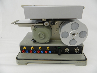
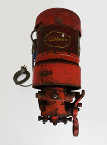
Machine - Shearing Motor, Sunbeam, 1960-69
With more and more woolsheds being connected to power lines, the need for electric shearing gear markedly increased from the 1960s onwards. The greater economy made electric gear an attractive proposition to many graziers. Requiring only an electric shearing motor, for small and medium scale operations, electric shearing motors were a more economical way of shearing a wool clip. The other option for graziers was Overhead shearing gear, which also required an Engine to provide shared power to a row of shearing stations. Still working, this Sunbeam Electric Shearing Motor – Heavy Duty Model, features a slow speed motor totally enclosed for protection against dust and insects. The full bearing down tube is easily removed and stored to be out of the way when not in use (not pictured). Providing 0.5 hp, which is twice the power ever needed for shearing sheep, this buffer allows for fluctuations in voltages that can occur in rural districts. Inventor Frederick Wolseley made the world's first commercially successful power-shearing system in Australia in 1888. US company Cooper, which had been founded in 1843 as a maker of sheep dip, began selling Wolseley equipment in the USA in 1895. The Chicago Flexible Shaft Company successfully entered the power-shearing market a few years later and entered into a joint venture with Cooper. It set up a branch in Sydney and sold shearing sets, and engines to power them, into the Australian market. In 1921 the US parent company, realising it needed to make products whose sales were not as seasonal as those of shearing equipment, made its first household appliances and branded them Sunbeam. In 1933, changes in exchange rates and taxes led the company to manufacture engines and shearing equipment in Australia via subsidiary Cooper Engineering, which changed its name to Sunbeam in 1946. Although most Australians know of this company as a major manufacturer of household appliances, its rural division flourished and retained the Sunbeam name for shearing equipment even after it was taken over by New Zealand company Tru-Test in 2001. This 0.5 horsepower vertical brushed motor air-cooled engine was designed to drive a single shearing plant. From the central cylinder which features a yellow “Sunbeam” sticker, a grey 240v power lead can be found on the left-hand side. A blue capacitor is located next to this power lead. Below, two legs extend and meet to form a foot which is fastened to a wall. On the right-hand side of the engine, a specification plate is located on the central cylinder. A yellow directional arrow sticker is located on the rotating section of the engine below the specification plate (location for photography, this section is designed to rotate and hence this sticker is not fixed in this location). At the rear of the cylinder, a plastic cap with small air cut outs protects the air-cooled engine from contaminants. At the front of the engine, the location for securing the bearing down tube is located. On the right-hand side of the lock for the bearing down tube is the handle, to which a string is often attached for switching the motor on and off by a shearer bent at the waist (not pictured). Sticker. Gold writing. Front of shearing motor “Sunbeam” Plate. Inscribed. Side of shearing motor. “Sunbeam / SHEARING MOTOR / MADE IN AUSTRALIA / 0.5 H.P. / 220/240 V / 1 PHASE A.C. / 4.0 AMPS / 50 C/S. / CONT. RTG. / 1425 R.P.M. / CLASS A INSUL / NO. J244560 / TYPE: NSB5C2/49." sheep sheering, shearing equipment, sunbeam, electric shearing motor -
 National Wool Museum
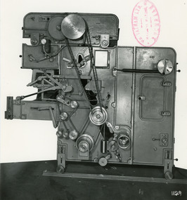
Photograph - Product Photograph, Patent Automatic Feed Machine
These are sales photographs for William Tatham Ltd. of Rochdale. These photographs are taken in the fitting shop at William Tatham Ltd. where final assembly would have taken place. An Automatic Feeding Machine automatically and sequentially supplies uncarded wool to carding machines, The photographed machine was made by William Tatham Ltd, a textile engineering company based in Rochdale, UK. Established in 1866 Tatham developed innovative textile machinery and send their products to Australia and other countries around the world.A black and white photo of a Patent Automatic Feed Machine in a portrait format. Black wiritng on the rear, typed with a typewriter.Front - mid left corner - Wm. TATHAM Ltd. ROCHDALE. Machine Maker Front bottom right corner - 1129 Rear - Patent Automatic Feed with Extended Hopper fitted with balanced pressure plate which operates through Variable Speed Device to regulate speed of spiked lattice in accordance with material in Hopper. Electro-Magnetic Clutch Drive to spiked lattice controlled by Mercery Switch on scale arm. Diagonal Scale Pan with improved knife edge suspension. Dual Trap Doors over Pan actuated by Solenoid. Automatic device to slow spiked lattice just prior to weigh being obtained. Ball or roller bearings to main shaft, combs and other parts. Self-aligning bearing to timing shaft etc.textile machinery, tatham, wool manufacture, carding, automatic feeding machine, wool