Showing 60 items matching "control cables "
-
 Moorabbin Air Museum
Book - Aircraft maintenance, Acceptable Methods, Techniques and Practices Aircraft Inspection, Repair & Alterations
... ...Control cables & terminals...Moorabbin Air Museum Moorabbin Airport 12 First Street Moorabbin melbourne Aircraft maintenance Aircraft wood structures Aircraft metal structures Fabric covering Control cables & terminals Aircraft hardware Corrosion protection Identification/testing/inspection of materials Aircraft equipment Windshields/enclosures & exits Hydraulic & pneumatic systems electrical systems Propellers / rotors & associated equipment Engines & fuel systems Radio & electronic systems Methods, techniques & practices acceptable for inspection & repair of civil aircraft, circa 1988 Acceptable Methods, Techniques and Practices Aircraft Inspection, Repair & Alterations Book Aircraft maintenance ...Methods, techniques & practices acceptable for inspection & repair of civil aircraft, circa 1988non-fictionMethods, techniques & practices acceptable for inspection & repair of civil aircraft, circa 1988aircraft wood structures, aircraft metal structures, fabric covering, control cables & terminals, aircraft hardware, corrosion protection, identification/testing/inspection of materials, aircraft equipment, windshields/enclosures & exits, hydraulic & pneumatic systems, electrical systems, propellers / rotors & associated equipment, engines & fuel systems, radio & electronic systems -
 Federation University Historical Collection
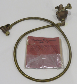
Object, Auto Engine Humidifier, c1930
... Brass unit and flexible tubing, stainless steel adjustment knob and copper coated spiral cover of control cable. Two spare fittings and two description cards. ...VIX Vapor humidifier, Wheaton, ILL, USA Brass unit and flexible tubing, stainless steel adjustment knob and copper coated spiral cover of control cable. Two spare fittings and two description cards. ...Brass unit and flexible tubing, stainless steel adjustment knob and copper coated spiral cover of control cable. Two spare fittings and two description cards. Decarbonizes the engine, sends a constant stream of moisture to the engine.Patented and patents pending in USA and foreign countries. VIX Vapor humidifier, Wheaton, ILL, USAengine humidifier, walter g. critchlow, vix vapour humidifier, vix vapor humidifier -
4th/19th Prince of Wales's Light Horse Regiment Unit History Room
Antenna Matching Unit MX-6707/VRC, E-Systems Inc, abt 1980
... Underneath the bottom portion are receptacles and controls. These include: a. antenna cable receptacle, b. control cable receptacle,and c. band control switch. ...Underneath the bottom portion are receptacles and controls. These include: a. antenna cable receptacle, b. control cable receptacle,and c. band control switch. ...Component of vehicle radio installations of the Regiment during 1980's. Vehicle installations included: AN/VRC 46, AN/VRC 49, and An/VRC 64The AMU consists of a metal body with a spring top section incorporating the thread for mounting the antenna. Underneath the bottom portion are receptacles and controls. These include: a. antenna cable receptacle, b. control cable receptacle,and c. band control switch. Also underneath is a drain screw and provision for fitting an earth strap. Serial No 1362radio, army, armoured corps, antenna systems -
4th/19th Prince of Wales's Light Horse Regiment Unit History Room
Antenna Matching Unit MX-6707/VRC
... Underneath the bottom portiion are receptacles and controls. These include: a. antenna cable receptacle, b. control cable receptacle, and c. band control switch. ...Underneath the bottom portiion are receptacles and controls. These include: a. antenna cable receptacle, b. control cable receptacle, and c. band control switch. ...Component of vehicle radio installations of the Regiment during 1980's. Vehicle installations included: AN/VRC 46, AN/VRC 49, and An/VRC 64The AMU consists of a metal body with a spring top section incorporating the thread for mounting the antenna. Underneath the bottom portiion are receptacles and controls. These include: a. antenna cable receptacle, b. control cable receptacle, and c. band control switch. Also underneath is a drain screw and provision for fitting an earth strap. Serial number 94104radio, antenna component, matching unit. -
4th/19th Prince of Wales's Light Horse Regiment Unit History Room
Antenna Matching Unit MX-6707/VRC
... Underneath the bottom portion are are receptacles and controls. These include: a. antenna cable receptacle, b. control cable receptacle, and c. band control switch. ...Underneath the bottom portion are are receptacles and controls. These include: a. antenna cable receptacle, b. control cable receptacle, and c. band control switch. ...Component of vehicle radio installations of the Regiment during 1980's. Vehicle installations included: AN/VRC 46, AN/VRC 49, and An/VRC 64The AMU consists of a metal body with spring top section incorporating the thread for mounting the antenna. Underneath the bottom portion are are receptacles and controls. These include: a. antenna cable receptacle, b. control cable receptacle, and c. band control switch. Also underneath is a drain screw and provision for fitting an earth strap.Serial number: 12932radio, antenna, matching unit, vehicle installations -
4th/19th Prince of Wales's Light Horse Regiment Unit History Room
Antenna Matching Unit MX-6707/VRC, abt 1980
... Underneath the bottom portion are receptacles and controls. These include: a. antenna cable receptacle, b. control cable receptacle, and c. band control switch. ...Underneath the bottom portion are receptacles and controls. These include: a. antenna cable receptacle, b. control cable receptacle, and c. band control switch. ...Component of vehicle radio installations of the Regiment during 1980's. Vehicle installations included: AN/VRC 46, AN/VRC 49, and An/VRC 64The AMU consists of a metal body with a spring top section incorporating the thread for mounting the antenna. Underneath the bottom portion are receptacles and controls. These include: a. antenna cable receptacle, b. control cable receptacle, and c. band control switch. Also underneath is a drain screw and provision for fitting an earth strapSerial number: 94141radio, antenna, matching unit, vehicle installations -
 Bendigo Military Museum
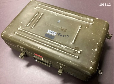
Equipment - MINE DETECTOR U.S, c.1967-73`
... . - Coil head, - Electronics box, - Ear phones and ear plugs, - Spare electronic modules, red, white, black, - Handle - extendable with controls, - cables. Electronics box has metallic label = model P.158. .... - Coil head, - Electronics box, - Ear phones and ear plugs, - Spare electronic modules, red, white, black, - Handle - extendable with controls, - cables. Electronics box has metallic label = model P.158. ...These mine detectors were made in the U.S.A. roughly 1967-1973. They were designated as portable transistorized metallic mine detectors.1. Case Aluminum, 2 piece drab olive, 8 strong retaining clips. 2. Detector Assy, and accessories. - Coil head, - Electronics box, - Ear phones and ear plugs, - Spare electronic modules, red, white, black, - Handle - extendable with controls, - cables. Electronics box has metallic label = model P.158. Serial 8407 etc - US Army. Case has transfer type labels: - “Detecting set mine, Portable metallic FSN 6665-966-7071 PO No. 3295” “Polar Industries Inc. Model P-158” Handle base has “8407” in Texta colour and metallic label, case carrying. “MFR name zero MFG 6” Part No. DZ136 - The lid has U.S. Property stamped on it. The NR 8407 is written on it in Texta.vietnam war, mine warfare, engineer mine clearance -
 Federation University Historical Collection
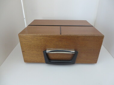
Equipment - Electrical Instrument, Moore Reed "Universal" Acoustic Coupler: Type TC301, c1980
... Top section hinged and folds back. inside are controls and cables for connecting to a computer. ...Top section hinged and folds back. inside are controls and cables for connecting to a computer. ...The Universal Acoustic Coupler was made and would have been used to connect a telephone to dial a computer remotely. The control panel is under the wooden flap. There is a power switch, full duplex switch, 500 Ma Fuse, CCITT Port. When not in use it can be folded up into a small timber carry case with handle.Wooden box with two sections that open. Top section hinged and folds back. inside are controls and cables for connecting to a computer. Instructions for use are on the lid. Front section has clips and folds down to a phone to placed in "speakers". English maker's plate and Melbourne supplier's plate with A.P.O. Permit No. C74/8/903 Serial No. 775326 moore reed, universal acoustic coupler, telephone, remote connection, computer connection -
4th/19th Prince of Wales's Light Horse Regiment Unit History Room
Amplifier Audio Frequency AM-1780/VRC, 1980's
... Solid metal radio harness control box with 10 cable sockets around sides and various control switches and line connections on face...4th/19th Prince of Wales's Light Horse Regiment Unit History Room 4/19 PWLH Regiment, Building 78 Simpson Barracks Macleod melbourne radio equipment 1780 box Serial No 33765 Solid metal radio harness control box with 10 cable sockets around sides and various control switches and line connections on face Amplifier Audio Frequency AM-1780/VRC Raven Industries Inc ...Solid metal radio harness control box with 10 cable sockets around sides and various control switches and line connections on faceSerial No 33765radio equipment, 1780 box -
 Melbourne Tram Museum
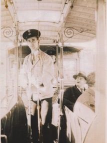
Photograph - Compact Diskette with photographs, Peter Wynd, "Eric Wynde Photos", 2016
... Compact Diskette within green plastic circular folder containing a photo of Eric Wynd at the controls of a cable car and MMTB certificate of service. ...image 1 - Photo of Eric at the cable tram controls with a light coloured summer uniform jacket and MMTB peaked cap. ...Compact Diskette within green plastic circular folder containing a photo of Eric Wynd at the controls of a cable car and MMTB certificate of service. image 1 - Photo of Eric at the cable tram controls with a light coloured summer uniform jacket and MMTB peaked cap. See history of object for further details and the htd3058doc.pdf file for further details of Eric and the donor. image 2 - image of MMTB certificate of service - 38 years, dated 6-4-1978, signed by the Chairman D. Snell, Deputy Chairman, Board Member and Secretary Mr. Aird. image 3 - of the CD container.trams, tramways, mmtb, cable trams, drivers, certificates, uniforms -
 Port Fairy Historical Society Museum and Archives
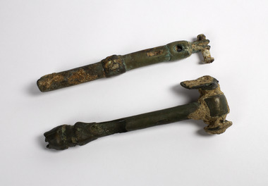
Vehicle - Artefact, 1930s
... It was possibly used to adjust control cables. The plane went down on the 15th February 1944 Flight Sgt. ...It was possibly used to adjust control cables. The plane went down on the 15th February 1944 Flight Sgt. ...Retrieved from crashed (during W.W.2) Avro Anson aircraft at Propeller Bay near Lady Julia Percy Island in 13 metres of water. Found adjacent to the remains of the engine and propeller in June 1993 by Peter Ronald. It was possibly used to adjust control cables. The plane went down on the 15th February 1944 Flight Sgt. J.H. MacLellen, Flight Sgt D.l. Baulderstone, LAC N.T. Kruck, LAC B.C. Ladyman were killed. A memorial was erected at the 'Crags' on the 14th of February 2015 . " At 0800 Anson AW878 of 2AOS took off from Mount Gambier to carry out a radius of action navigation exercise to Lady Julia Percy Island (located off the Victorian coast, midway between Portland and Warrnambool) and back to Mount Gambier. By 1230 it was overdue, and that afternoon a search was instituted. No radio messages had been received from the Anson, although it had been seen during the exercise by another aircaraft. At 1430 part of the mainplane was sighted on Lady Julia Percy Island. Subsequently a fishing boat searched in the vicinity of the island and passed through small pieces of wreckage strewn over about 3 miles. A further search uncovered wreckage which identified the plane beyond doubt, including fuel tank bay cover with AW878 penciled on it, and a Mae West which had been signed out by one of the crew. The bodies of the four crew were never located." This information comes from a report at Mt Gambier Airport where the plane was stationed.Two small pieces of metal that bring the reality of war to our shoresArtefact from crashed aircraft at Lady Julia Percy islandlocal history, transport, aviation, aircraft, lady julia percy island, j.h. maclellen, d.l. baulderstone, n.t. kruck, b.c. ladyman -
 Melbourne Tram Museum
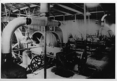
Photograph - Black and White - Nicholson & Gertrude Street Engine House interior
... Shows the interior of the cable tram engine house that was located on the corner of Gertrude Street and Nicholson Street in Fitzroy. Shows the steam pipes to two of the engine cylinders, the control equipment, and large cable winding wheels. ...Melbourne Tram Museum 8 Wallen Road Hawthorn melbourne Shows the interior of the cable tram engine house that was located on the corner of Gertrude Street and Nicholson Street in Fitzroy. Shows the steam pipes to two of the engine cylinders, the control equipment, and large cable winding wheels. ...Shows the interior of the cable tram engine house that was located on the corner of Gertrude Street and Nicholson Street in Fitzroy. Shows the steam pipes to two of the engine cylinders, the control equipment, and large cable winding wheels. An MMTB poster titled Melbourne Tramways Past and President (see Reg Item 6368), captions the photo as "Nicholson Sreet Power House - the last to operate" The facility ceased operation in 1940 though the equipment was retained until 1941. Yields information about the interior of the Gertrude Street or Nicholson Street cable tram engine houseBlack and white photograph - interior of the Engine house on the corner of Gertrude and Nicholson Streets prior to closure in 1940.tramways, trams, coburg, cable cars, engine house, nicholson street, gertrude street, steam engines -
 Ballarat Tramway Museum
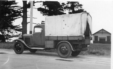
Photograph - Black & White Photograph/s, State Electricity Commission of Victoria (SECV), c1935
... Photographed in Wendouree Parade with two different boat sheds in the background. 1705.2 - view with drivers side cover opened, showing equipment arrangement. 1705.3 - close up view of motor generator set and controls and one of the oxy acetylene bottles. 1705.4 - view showing equipment laid out on the roadway, welding cover, seat, grinder, cables, shovels, welding mask etc. 1705.5 - close up view of motor generator control panel and associated cables. 1705.6 - view of side of truck showing all equipment. 1705.7 - vertical format photo from rear of truck showing equipment laid out and wandering lead connected to the overhead. ...Photographed in Wendouree Parade with two different boat sheds in the background. 1705.2 - view with drivers side cover opened, showing equipment arrangement. 1705.3 - close up view of motor generator set and controls and one of the oxy acetylene bottles. 1705.4 - view showing equipment laid out on the roadway, welding cover, seat, grinder, cables, shovels, welding mask etc. 1705.5 - close up view of motor generator control panel and associated cables. 1705.6 - view of side of truck showing all equipment. 1705.7 - vertical format photo from rear of truck showing equipment laid out and wandering lead connected to the overhead. ...Set of 8 black and white photographs of the SEC Ballarat track welding truck, Reg. No. 119 341. Truck is a British Bedford truck, model WHG, built by GMH Melbourne between 1932 and 1934. Has a fabric roof, chassis fitted with a tray top body, side tool box, metal frame and covered with canvas, fitted out with a motor generator set, welding equipment and oxy acetylene bottles. Also fitted with a spot light - 'Auto Reel Lite". - See Related Items sheet on truck notes provided by Kevin Oates, MFESB workshops, 4/2001. (Scan of this sheet of the Kodak folder added 15-8-2017 - see pdf file.) 1705.1 - side on view of truck with covers down, except for opening at back. Photographed in Wendouree Parade with two different boat sheds in the background. 1705.2 - view with drivers side cover opened, showing equipment arrangement. 1705.3 - close up view of motor generator set and controls and one of the oxy acetylene bottles. 1705.4 - view showing equipment laid out on the roadway, welding cover, seat, grinder, cables, shovels, welding mask etc. 1705.5 - close up view of motor generator control panel and associated cables. 1705.6 - view of side of truck showing all equipment. 1705.7 - vertical format photo from rear of truck showing equipment laid out and wandering lead connected to the overhead. Also shows high voltage wires on a power pole fitted with a bracket arm. 1705.8 - view of truck from the front, with SEC symbol on side, with a covers closed. Thought to be photographed at loop in Wendouree Parade on the View Point line, near Mill St. Prints when donated to the BTM were contained within a red and yellow "Kodak" folder. Folder stored with catalogue worksheet. On rear of folder in ink is number "53569" and stamped on the front is number "984" and written in front top left hand cover, "8 prints" and in top right hand corner word "Sarah". See Notes provided by Kevin Oates of the MFESB (Metro Fire Brigade Melbourne) Thornbury workshops on the truck, manufacture and engine. A survey of Wendouree Parade on 22/4/2001 did not show the boat sheds or power lines featured in the photographed. Thought to be in vicinity of Power station because of the high voltage lines on the power poles.Stamped on rear in black ink, "984" on photos 1705.3 to 1705.8.trams, tramways, welding truck, trackwork, secv, wendouree parade -
 Port of Echuca
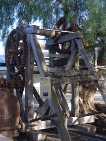
Machine - Log Winch, Early 1920
... The structure is composed of red gum timber with four main posts with diagonal braces supporting a cog system and winch cable on the drive shaft at the top of the structure There is a platform on one side of the structure to enable the operator to reach the operating levers. There was also a rod control...Port of Echuca 74 Murray Esplanade Echuca the-murray The log winch is a rare and unusual item of considerable interest in the context of the Echuca and Murray River Red Gum industry The winch is of historical significance for its association with the Evans Sawmill from early to mid-twentieth century, It helps demonstrate the role of the industry in the exploitation of the Murray River red gum timber, the process of converting the forests to a saleable commodity and the relationship between the industry the river Echuca township and the transport facilities of the wharf, paddlesteamers and the railway, The log winch is a rare and unusual item of considerable interest in the context of the Echuca and Murray River Red Gum industry, and the transport industry of Victoria, The structure is composed of red gum timber with four main posts with diagonal braces supporting a cog system and winch cable on the drive shaft at the top of the structure There is a platform on one side of the structure to enable the operator to reach the operating levers. There was also a rod control ...The log winch is a rare and unusual item of considerable interest in the context of the Echuca and Murray River Red Gum industry The winch is of historical significance for its association with the Evans Sawmill from early to mid-twentieth century, It helps demonstrate the role of the industry in the exploitation of the Murray River red gum timber, the process of converting the forests to a saleable commodity and the relationship between the industry the river Echuca township and the transport facilities of the wharf, paddlesteamers and the railway,The log winch is a rare and unusual item of considerable interest in the context of the Echuca and Murray River Red Gum industry, and the transport industry of Victoria,The structure is composed of red gum timber with four main posts with diagonal braces supporting a cog system and winch cable on the drive shaft at the top of the structure There is a platform on one side of the structure to enable the operator to reach the operating levers. There was also a rod control to regulate the winch engine and boiler. -
 Bendigo Military Museum
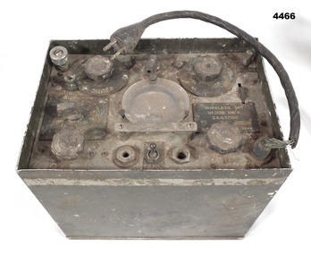
Equipment - WIRELESS SET 1944, 1944
... There is a small length of cable coming from the control panel to a 4 pin plug. On the outside of case is the phrase D (arrow up)D 208 MKII...An image of this type of wireless set in operation can be found in the AWM Collection: P02952.012 081815 WIRELESS WWII Plaque on control panel "WIRELESS SET - ZAA 2088 SERIAL NUMBER 168 DATE = 1944" Aluminium box, cover missing. The top has various dials, jacks and one gauge. There is a small length of cable ...This is a 6 valve portable transceiver, made in Australia from a British design. It was only used for C.W. (morse code). Its frequency was in the range of 2.5-3.5MHz. Output power 0.5-5 watts. Use was for commando and infantry patrols up to battalion level. It had an external battery pack for low and high voltage supply. 1 man operation in Tropics. An image of this type of wireless set in operation can be found in the AWM Collection: P02952.012 081815 Aluminium box, cover missing. The top has various dials, jacks and one gauge. There is a small length of cable coming from the control panel to a 4 pin plug. On the outside of case is the phrase D (arrow up)D 208 MKIIPlaque on control panel "WIRELESS SET - ZAA 2088 SERIAL NUMBER 168 DATE = 1944"wireless, wwii -
4th/19th Prince of Wales's Light Horse Regiment Unit History Room
Training Set, Universal, Wireless, No 1, about 1948
... In the case of each operator, the microphones and headphones plug into an "operator's control unit" fitted to the table in front of each operator. The units also house a morse key, and are connected to the instructor's set by four-core cable. ...In the case of each operator, the microphones and headphones plug into an "operator's control unit" fitted to the table in front of each operator. The units also house a morse key, and are connected to the instructor's set by four-core cable. ...The kit is packed in 2 wooden transit boxes. The Training Set is a semi-portable instrument for training operators in morse reading and sending and R.T. communication. The set comprises audio oscillators for morse reading, morse interference and background noise interference, power supply for microphones, an audio amplifier, and a switch board for group working with up to six independent, contained in the instructor's set. The instructor and each operator under training has a receiver-head gear, a hand microphone and a morse key. The instructor has an additional morse key used for providing morse interference. In the case of each operator, the microphones and headphones plug into an "operator's control unit" fitted to the table in front of each operator. The units also house a morse key, and are connected to the instructor's set by four-core cable. Plug and socket connections are used. The apparatus may be used for a class of up to 36 operators. Working Instructions - filed on Object Data Record radio, wireless, training set -
4th/19th Prince of Wales's Light Horse Regiment Unit History Room
Radio Installation
... VRC, one radio RT841/PRC77, one amplifier AM2060/GRC radio installations and the harness - AM 1780/VRC, three C2298 control boxes, one C2299 rebroadcast box, various cabling and two antenna systems...VRC, one radio RT841/PRC77, one amplifier AM2060/GRC radio installations and the harness - AM 1780/VRC, three C2298 control boxes, one C2299 rebroadcast box, various cabling and two antenna systems Radio Installation ...Installation as used by the Regiment in M113 family of vehiclesRadio Installation AN/VRC 46, AN/GRC 160, AN/VIC1(V) Harness. VHF radio installation as used in M113 family of vehicles. Consists of two mounting trays MT1029?VRC, one radio RT841/PRC77, one amplifier AM2060/GRC radio installations and the harness - AM 1780/VRC, three C2298 control boxes, one C2299 rebroadcast box, various cabling and two antenna systemsRT 524 - No 58347 RT841/PRC 77 - No 1835. AM2060GRC - No 660. AM1780/VRC - No 4841. Antenna Matching Units - Nos 94784 & 13050 radio installations, m113, armour -
4th/19th Prince of Wales's Light Horse Regiment Unit History Room
Junction Box 4 Way, 1950s - 60s
... Four way junction box of aluminium construction used as a cable splitter in a wireless control harness....4th/19th Prince of Wales's Light Horse Regiment Unit History Room 4/19 PWLH Regiment, Building 78 Simpson Barracks Macleod melbourne Equipment used by the Regiment junction box wireless control harness ZA 46982 Four way junction box of aluminium construction used as a cable splitter in a wireless control harness. ...Equipment used by the RegimentFour way junction box of aluminium construction used as a cable splitter in a wireless control harness.ZA 46982junction box, wireless control harness -
 Kiewa Valley Historical Society
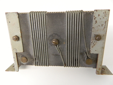
Resistor 2000 Amperes, circa mid to late 1900's
... Although it is relatively small in size it is part of the controlling mechanism for the supply of a non polluting energy source for home and industrial use. kiewa hydro electricity scheme victorian state electricity commission transformers On one side it is scribed "0.2 OHMS" and underneath this "10 AMPS" This mainly metal and wire resistor has been built of copper and brass and designed to carry a current of 2000 Amperes. Wires are wound around a non conductive cement block which has grooves on the top and bottom ledges to hold the wires snuggle into place. At the rear there are three connection rods which have long 5mm thick screws (to fasten cable ...This resistor was part of the Hydro generator control metering system which displays what electricity is produced at the underground generators. The control centre can be hundreds of meters above the generators and this resistor reduces the large current to a small voltage entering a calibrated control monitor. This resistor is highly significant to the Kiewa Valley because it represents a major construction and ongoing operational industry dealing with the supply of hydro electricity to Victoria. Although it is relatively small in size it is part of the controlling mechanism for the supply of a non polluting energy source for home and industrial use.This mainly metal and wire resistor has been built of copper and brass and designed to carry a current of 2000 Amperes. Wires are wound around a non conductive cement block which has grooves on the top and bottom ledges to hold the wires snuggle into place. At the rear there are three connection rods which have long 5mm thick screws (to fasten cable ends)On one side it is scribed "0.2 OHMS" and underneath this "10 AMPS"kiewa hydro electricity scheme, victorian state electricity commission, transformers -
 Nhill Aviation Heritage Centre
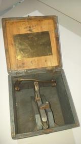
Tool - Control cable tension gauge
... Control cable tension gauge...Nhill Aviation Heritage Centre 1 Aerodrome Road Nhill grampians cable tension tool tool Box has brass plate with tension scale for various aircraft types, tool has 76 stamped on the handle. 140.1 Green wooden carry box with hinged lid and metal latch. 140.2 Metal device with spring loaded handle, rollers and pointer assembly and graduations. Tool Control cable tension gauge ...140.1 Green wooden carry box with hinged lid and metal latch. 140.2 Metal device with spring loaded handle, rollers and pointer assembly and graduations. Box has brass plate with tension scale for various aircraft types, tool has 76 stamped on the handle.cable tension tool, tool -
Frankston RSL Sub Branch
Recorder, Camera
... controls on the narrow side of the recorder which are marked "START, 0, 5, 10, 15, END" and "DULL, S.S. BRIGHT". The recorder magazine is inscribed with the Department of Defence mark and the following "14A/4008, G.G.S., RECORDER, MAGAZINE, MKII". This is a Camera Gun Recorder used in conjunction with a Gyro Gun Sight type 14A, G. G. S. Recorder Mk2 contained in a wooden box with hinged lid and retaining catch. The recorder consists of a metal enclosure with an electrical power supply cable ...This is a Camera Gun Recorder used in conjunction with a Gyro Gun Sight type 14A, G. G. S. Recorder Mk2 contained in a wooden box with hinged lid and retaining catch. The recorder consists of a metal enclosure with an electrical power supply cable fitted with a three pole female plug connector. A small access cover in the enclosure can be opened to replace the Recorder Magazine. There is a transparent aperture window on the underside of the enclosure.The recorder enclosure is inscribed with the Department of Defence mark and the following, "14A/3629, G.G.S., RECORDER, Mk2, 24V., XX 12012". There are small controls on the narrow side of the recorder which are marked "START, 0, 5, 10, 15, END" and "DULL, S.S. BRIGHT". The recorder magazine is inscribed with the Department of Defence mark and the following "14A/4008, G.G.S., RECORDER, MAGAZINE, MKII". raaf, royal australian air force, gun, fighter, photography, ww2, world war 2, camera, aircraft, bomber, aerial -
 Australian Gliding Museum
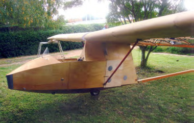
Machine - Glider – Sailplane, 2015
... However, he has added something of his own to the design by replacing the cable runs in the wings with control rods. The glider is substantially complete. ...However, he has added something of his own to the design by replacing the cable runs in the wings with control rods. The glider is substantially complete. ...The Salamandra is a Polish glider designed by Waclaw Czerwinski at the Military Glider Workshops in Krakow in 1936. This glider, designated “W.W.S.1”, was produced in substantial numbers prior to the second world war and used in Poland and some other eastern European countries for training pilots. Only one example survived the war, hidden away in the village of Goleszow in Silesia. In addition, no technical drawings could be found, so when the glider was discovered, the Gliding Institute being keen to re-establish gliding in Poland, used the glider to draw up new plans for construction. Five were built for the Institute in 1947 before production was resumed of the “Salamandra 48” at the SZD Jezow Workshops. Improvement were made by adding airbrakes and structural changes for the “Salamandra 49” and a windscreen and larger tailplane were changes adopted for the “Salamandra 53”. An export version designated “53A” was sold to and built under licence in China. Production of the Salamandra ceased in the early 1960s. Total production may have been in excess of 500. The glider was well regarded as a light weight trainer capable of soaring performance. The Museum’s replica was built by Ray Ash and may be may be classified as a “Salamandra 53”. However, he has added something of his own to the design by replacing the cable runs in the wings with control rods. The glider is substantially complete. The wings and tail / rudder surfaces have been covered with poly-fibre fabric. The fuselage woodwork is sealed with varnish. In addition to the finishing work (including painting) and rigging of the main components, the linkages for Ray’s control rod modification may need further engineering to make them operational. The Ray Ash Salamandra is the first of the type to appear in Australia. The Salamandra did not play any role in the development of gliding in Australia in the early years. However, it is an important exhibit in that it shows in tangible form a nacelle fuselage training glider in configuration and construction detail. As such it revisits the pioneering era of the 1930s and 1940s in Australia when wood, wire and fabric were the rule and the nacelle primary glider was generally the first step up for pilots who had mastered the basics in an open primary.Nacelled solo training glider of traditional wood and fabric construction. Construction incomplete.Noneaustralian gliding, sailplane, glider, salamandra, czerwinshi, poland, ash -
 Bendigo Historical Society Inc.
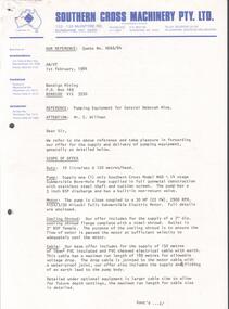
Letter - KANGAROO FLAT GOLD MINE COLLECTION: LETTER SOUTHERN CROSS MACHINERY TO BENDIGO MINING, 1st February 1984
... The Southern Cross submersible pump is costed at $7785.00, and the electrical control cubicvle at $1510, PVC insulated cable at $4.40 m. A brochure for the pump and the pump characteristic curves are appended....The Southern Cross submersible pump is costed at $7785.00, and the electrical control cubicvle at $1510, PVC insulated cable at $4.40 m. A brochure for the pump and the pump characteristic curves are appended. ...Letter 2 page with attachments, 1 February 1984 ,Southern Cross Machinery Ltd.,to Bendigo Mining, re pumping equipment for Central Deborah Mine. The 'offer for the supply and delivery of pumping equipment' is detailed in the letter. The Southern Cross submersible pump is costed at $7785.00, and the electrical control cubicvle at $1510, PVC insulated cable at $4.40 m. A brochure for the pump and the pump characteristic curves are appended.bendigo, gold mining, central deborah gold mine, bendigo, mining, gold mining, dewatering, pumping equipment, southern cross machinery, c. willman, bendigo mining nl. -
Glenelg Shire Council Cultural Collection
Equipment - Equipment - Diving amplifier, n.d
... Rectangular steel case, black, handles each end, fittings for communication cables on left hand end, fittings for power supply on right hand end, control panel at front of case. ...Rectangular steel case, black, handles each end, fittings for communication cables on left hand end, fittings for power supply on right hand end, control panel at front of case. ...Port of Portland CollectionFront: Diving amplifier equipment/TYPE 957 SERIAL No 260/ Navy Department Bureau of Ships/ date 11-4-43/ GUIDED RADIO CORPORATION NEW YORK N.Y.port of portland archives -
Glenelg Shire Council Cultural Collection
Equipment - Communication Cable for Diving Amplifier, n.d
... Rectangular steel case, black, handles each end, fittings for communication cables on left hand end, fittings for power supply on right hand end, control panel at front of case. ...Rectangular steel case, black, handles each end, fittings for communication cables on left hand end, fittings for power supply on right hand end, control panel at front of case. ...Port of Portland Collection Black communication Cable for Diving amplifier equipment capable of surface to diver communications for three divers. Each end of the cable is a connector and connects helmet to amplifier. Rectangular steel case, black, handles each end, fittings for communication cables on left hand end, fittings for power supply on right hand end, control panel at front of case. Alloy knobs, speaker.port of portland archives -
 Flagstaff Hill Maritime Museum and Village
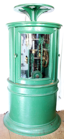
Machine - Dioptric Apparatus, mid 19th century
... The mechanism consisted of a large weight attached by a cable through the centre of the lighthouse to the top where the cable wrapped around a barrel, drum or wheels that controlled the speed of the lights rotation by a clockwork mechanism. ...The mechanism consisted of a large weight attached by a cable through the centre of the lighthouse to the top where the cable wrapped around a barrel, drum or wheels that controlled the speed of the lights rotation by a clockwork mechanism. ...Before the introduction of electricity, lighthouses had a clockwork mechanism that caused the lens to rotate with a light source inside that was either powered by Kerosene or Colza oil. The mechanism consisted of a large weight attached by a cable through the centre of the lighthouse to the top where the cable wrapped around a barrel, drum or wheels that controlled the speed of the lights rotation by a clockwork mechanism. The keeper would crank the clockwork mechanism, which would lift the weight ready for the next cycle similar to an old grandfather clock mechanism. Once the weight lifted to its apex at the bottom of the first landing, the keeper would let it fall, which would pull on the cable, which would, in turn, operate a series of gears activating the rotation of the Fresnel optical lens, which would then rotate to create the lighthouse’s unique light speed of rotation characteristic. Creating a specific characteristic required a way to regulate the speed of the rotation, and was important as sailors could identify a particular light by its speed and time between flashes. The weight had to fall at a certain rate to create the proper rotation speed of the lens and a regulator within the mechanism accomplished this. History: From 1851, Chance Brothers became a major lighthouse engineering company, producing optical components, machinery, and other equipment for lighthouses around the world. James Timmins Chance pioneered placing lighthouse lamps inside a cage surrounded by Fresnel lenses to increase the available light output these cages, are known as optics and they revolutionised lighthouse design. Another important innovation from Chance Brothers was the introduction of rotating optics, allowing adjacent lighthouses to be distinguished from each other by the number of times per revolution the light flashes. The noted English physicist and engineer, John Hopkins invented this system while employed at Chance Brothers. Chance Brothers and Company was a glass works and originally based in Spon Lane, Smethwick, West Midlands England. The company became a leading glass manufacturer and a pioneer of British glass making technology. The Chance family originated in Bromsgrove as farmers and craftsmen before setting up a business in Smethwick near Birmingham in 1824. They took advantage of the skilled workers, canals and many other industrial advances taking place in the West Midlands at the time. Robert Lucas Chance (1782–1865), known as 'Lucas', bought the British Crown Glass Company's works in Spon Lane in 1824. The company specialised in making crown window glass, the company ran into difficulty and its survival was guaranteed in 1832 by investment from Chance's brother, William (1788 – 1856). William owned an iron factoring business in Great Charles Street, Birmingham. After a previous partnership that Lucas had dissolved in 1836, Lucas and William Chance became partners in the business which was renamed, Chance Brothers and Company. Chance Brothers invented many innovative processes and became known as the greatest glass manufacturer in Britain. In 1848 under the supervision of Georges Bontemps, a French glass maker from Choosy-le-Roi, a new plant was set up to manufacture crown and flint glass for lighthouse optics, telescopes and cameras. Bontemps agreed to share his processes that up to then had been secret with the Chance Brothers and stayed in England to collaborate with them for six years. In 1900 a baronetcy was created for James Timmins Chance (1814–1902), a grandson of William Chance, who had started the family business in 1771 with his brother Robert. Roberts grandson, James became head of Chance Brothers until his retirement in 1889 when the company became a public company and its name changed to Chance Brothers & Co. Ltd. Additional information: Lighthouses are equipped with unique light characteristic or flashing pattern that sailors can use to identify specific lighthouses during the night. Lighthouses can achieve distinctive light characteristics in a few different ways. A lighthouse can flash, which is when brief periods of light interrupt longer moments of darkness. The light can occult, which is when brief periods of darkness interrupt longer moments of light. The light can be fixed, which is when the light never goes dark. A lighthouse can use a combination of flashing, oscillating, or being fixed in a variety of combinations and intervals to create individual light characteristics. It is a common misconception that a lighthouse's light source changes the intensity to create a light characteristic. The light source remains constant and the rotating Fresnel lens creates the various changes in appearance. Some Fresnel lenses have "bulls-eye" panels create beams of light that, when rotated between the light and the observer, make the light appear to flash. Conversely, some lenses have metal panels that, when rotated between the light and the observer, make the light appear to go dark. This Dioptric clockwork apparatus used to turn a lighthouse optical lens is very significant as it is integral to a lighthouses operation, we can also look at the social aspect of lighthouses as being traditionally rich with symbolism and conceptual meanings. Lighthouses illustrate social concepts such as danger, risk, adversity, challenge and vigilance but they also offers guidance, salvation and safety. The glowing lamp reminds sailors that security and home are well within reach, they also symbolize the way forward and help in navigating our way through rough waters not just on the oceans of the world but in our personal lives be it financial, personal, business or spiritual in nature. Nothing else speaks of safety and security in the face of adversity and challenge quite the way a lighthouse does. Revolving dioptric clockwork apparatus used to turn a Fresnel optical lighthouse lens. A cylindrical cast metal pillar and cabinet painted green with 3 glass doors enclosing the top section. Inside the pillar/cabinet is a large clockwork mechanism used to turn and regulate a lighthouse light by means of weights and a chain attached to same. One door has the name "Adams Mare" in metallic dots similar to "Braille" to the inside edge of door frame.shipwrecked-coast, flagstaff-hill, flagstaff-hill-maritime-museum, flagstaff hill, maritime-museum, shipwreck-coast, warrnambool, flagstaff-hill-maritime-village, revolving dioptric mechanism, dioptric mechanism for lighthouse, lighthouse clockwork timing mechanism, acetylene lighthouse light mechanism, 19th century lighthouse mechanism, kerosene light, fresnel lenses, colza oil, chance brothers -
 Federation University Historical Collection
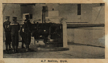
Photograph - Black & white photograph, 4.7 Naval Gun - South Africa, c1901
... These improvised carriages lacked recoil buffers and hence in action drag shoes and attachment of the carriage by cable to a strong point in front ofthe gun were necessary to control the recoil. ...These improvised carriages lacked recoil buffers and hence in action drag shoes and attachment of the carriage by cable to a strong point in front ofthe gun were necessary to control the recoil. ...British forces in the Second Boer war were initially outgunned by the long range Boer artillery. Captain Percy Scott of HMS Terrible first improvised timber static siege mountings for two 4-7 guns from the Cape Town coastal defences, to counter the Boers' "Long Tom" gun during the Siege of Ladysmith in 1899-1900. Captain Scott then improvised a travelling carriage for 4-7 inch guns removed from their static coastal or ship mountings to provide the army with a heavy field gun. These improvised carriages lacked recoil buffers and hence in action drag shoes and attachment of the carriage by cable to a strong point in front ofthe gun were necessary to control the recoil. They're manned by Royal Navy crews and required up to 32 oxen to moveIndividual image from photographed poster of tobacco and cigarette cards.second boer war, boer artillery, 4-7 guns, captain percy scott, hms terrible, cape town, "long tom", siege of ladysmith -
 Ballarat Tramway Museum
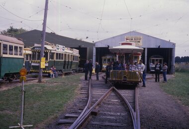
Slide - BTPS - cable tram set operations - Begonia Festival - set of 5, David Frost, Mar. 1987
... Set of five colour slides of the Newton Williams and Darryl Hawksworth motorised cable tram set operating in Wendouree Parade during the 1987 March Begonia Festival. Photos by David Frost. 1 - At the depot 2 - At the depot with Roy Sheedy on the trailer and Warren Doubleday on the controls. 3 - with passengers loaded and Bill Scott as conductor 4 - At Gardens Loop with tram 40 5 - ditto...Ballarat Tramway Museum South Gardens Reserve Wendouree Parade Ballarat Ballarat goldfields Set of five colour slides of the Newton Williams and Darryl Hawksworth motorised cable tram set operating in Wendouree Parade during the 1987 March Begonia Festival. Photos by David Frost. 1 - At the depot 2 - At the depot with Roy Sheedy on the trailer and Warren Doubleday on the controls. 3 - with passengers loaded and Bill Scott as conductor 4 - At Gardens Loop with tram 40 5 - ditto Yields information about the BTPS Operation of the motorised cable tramset for the 1987 Begonia Festival. tramways BTPS cable trams begonia festival gardens loop tram 40 tram 171 Colour Slide - green/white plastic mounts - set of 5 Slide BTPS - cable tram set operations - Begonia Festival - set of 5 David Frost ...Set of five colour slides of the Newton Williams and Darryl Hawksworth motorised cable tram set operating in Wendouree Parade during the 1987 March Begonia Festival. Photos by David Frost. 1 - At the depot 2 - At the depot with Roy Sheedy on the trailer and Warren Doubleday on the controls. 3 - with passengers loaded and Bill Scott as conductor 4 - At Gardens Loop with tram 40 5 - dittoYields information about the BTPS Operation of the motorised cable tramset for the 1987 Begonia Festival.Colour Slide - green/white plastic mounts - set of 5tramways, btps, cable trams, begonia festival, gardens loop, tram 40, tram 171 -
 Ballarat Tramway Museum
Manual, Doug Prosser, "General Electric Data for Car Equipment Maintenance", 1998
... Includes: · C129-A Master Controller, · DA82C Coupler sockets, · MS-14-G switch, · MS-46-H switch. 16 Dimensions of Electrical Apparatus used with 600-volv Type M railway control equipment, (Sheet 15383, dated 2/1/1924) - 1 sheet including · C-169-A Controller · DA-69-B Coupler Socket and DC-66-C Coupler Plug · MS-14-G Switch · MS-46-H-Switch 17 Method of Making Tap Connections for Car Cables -= SD 15468, 1/11/1924, 1 page 18 The Repair of 600 Volt Railway Motor Armatures, 64408, 9/2/1924, 4 pages 19 Proper Method of Mounting and Dismounting Railway Motor Pinions. - 2 pages 20 Pinion Pullers for Railway Motors - 2 pages, dated 8/1/1924. 21 The Care of Railway Motor Bearings - 4 pages 22 Oil Scraper Rings for Air Compressors - 64590 - May 1924 - 1 page 23 Finger Bases for type K 63 controller 1 page 24 Adjustment of Drum Controller fingers - 29/1/1924, 64600A - 1 page 25 Star Wheels for Type K Controllers - 64603 - 1 page 26 Soldering Aluminium Controller Cylinder Castings - 2 pages 27 Porcelain Bolt Insulators for Railway Service - and drawing on rear showing mounting arrangement of resistor Grids - 2 pages. ...Includes: · C129-A Master Controller, · DA82C Coupler sockets, · MS-14-G switch, · MS-46-H switch. 16 Dimensions of Electrical Apparatus used with 600-volv Type M railway control equipment, (Sheet 15383, dated 2/1/1924) - 1 sheet including · C-169-A Controller · DA-69-B Coupler Socket and DC-66-C Coupler Plug · MS-14-G Switch · MS-46-H-Switch 17 Method of Making Tap Connections for Car Cables -= SD 15468, 1/11/1924, 1 page 18 The Repair of 600 Volt Railway Motor Armatures, 64408, 9/2/1924, 4 pages 19 Proper Method of Mounting and Dismounting Railway Motor Pinions. - 2 pages 20 Pinion Pullers for Railway Motors - 2 pages, dated 8/1/1924. 21 The Care of Railway Motor Bearings - 4 pages 22 Oil Scraper Rings for Air Compressors - 64590 - May 1924 - 1 page 23 Finger Bases for type K 63 controller 1 page 24 Adjustment of Drum Controller fingers - 29/1/1924, 64600A - 1 page 25 Star Wheels for Type K Controllers - 64603 - 1 page 26 Soldering Aluminium Controller Cylinder Castings - 2 pages 27 Porcelain Bolt Insulators for Railway Service - and drawing on rear showing mounting arrangement of resistor Grids - 2 pages. ...A black plastic folder containing a set of 38 General Electric Data Sheets for MMTB and tramway trust equipment, dated July 8 1924. Contained in folder with flexible clips. Pages have been punched with four holes. Copy of document made for BTM Feb 1998 by Doug Prosser. For scan of list - see btm780sheet.pdf General Electric Data for Car Equipment Maintenance Contents For scan see btm780d1 (5 pages) Title sheet Data contents summary sheet showing manual prepared for Melbourne & Metropolitan Tramways Board Including Footscray Tramway Trust Hawthorne Tramways Trust Melbourne, Brunswick and Coburg Tramway Trust Prahran and Malvern Tramways Trust. 2 sheets dated July 8, 1924 giving equipment schedules for the various operators, and diagrams. - hard to read the background sheet information. Does not reference the tramcars. For scan see btm780d2 (54 sheets - items 1 to 27) 1. Methods of Removing the Armature from Box Frame Railway Motors Dated 9/1924, 7 pages 2. Instructions for order Magnet Frames for Railways and Mine Haulage Motors 2 pages, not dated 3 Winter Covers for Ventilated Railway Motors - 2 pages 4 Better Commutation for Railway Motors - 1 page 5 Commutator Grooving Machines - 1 page 6 Railway Motor Armature Coils - 2 pages 7 Carbon Brushes for Railway motors - including brush pressure adjustment - 2 pages 8 Renewable Carbon-Way Brush holders for Railway Motors - 2 pages 9 Commutator Grooving Machines (2nd version) - 2 pages 10 The Repair of Railway Motor Commutators - 3 pages 11 Dimensions of Electrical Apparatus used with 600-volv Type PC railway control equipment, (Sheet 15380, dated 2/1/1924) - 1 sheet including · US-13-E Trolley Base, · MS-118-A main switch, · MA-13-F Fuse Box, · MD3 - lightning Arrester, · BJ-386-B Distributing Box, · Type BG Railway Resistors. 12 Connections of Type KM-63-BR Railway Controllers and Equipment - Drawing 15257, 1 page, dated 1/3/1921 with dimension details on rear of type K-63-BR railway controller equipment including: · SG Resister, · BK-13-A Insulator, · MR11 - Circuit breaker, · MD3 - Lightning Arrester box, · K63-BR Controller, · US15C Trolley Base. 13 Method of Supporting Railway Resistors using Porcelain Bolt insulators for 600 and 1500 Volt Work. Drawing dated 1/11/1923, No. 15249B - 1 page 14 Dimensions of Electrical Apparatus used with 600-volv Type M railway control equipment, (Sheet 15381, dated 2/1/1924) - 1 sheet including · US-13-E Trolley Base, · MS-118-A main switch, · MA-13-F Fuse Box, · MD3 - lightning Arrester, · BJ-386-B Distributing Box, · Type BG Railway Resistors. 15 Dimensions of Electrical Apparatus used with 600Volt, Type PC Railway Control Equipment. Drawing No. 15382, dated 2/1/1924. Includes: · C129-A Master Controller, · DA82C Coupler sockets, · MS-14-G switch, · MS-46-H switch. 16 Dimensions of Electrical Apparatus used with 600-volv Type M railway control equipment, (Sheet 15383, dated 2/1/1924) - 1 sheet including · C-169-A Controller · DA-69-B Coupler Socket and DC-66-C Coupler Plug · MS-14-G Switch · MS-46-H-Switch 17 Method of Making Tap Connections for Car Cables -= SD 15468, 1/11/1924, 1 page 18 The Repair of 600 Volt Railway Motor Armatures, 64408, 9/2/1924, 4 pages 19 Proper Method of Mounting and Dismounting Railway Motor Pinions. - 2 pages 20 Pinion Pullers for Railway Motors - 2 pages, dated 8/1/1924. 21 The Care of Railway Motor Bearings - 4 pages 22 Oil Scraper Rings for Air Compressors - 64590 - May 1924 - 1 page 23 Finger Bases for type K 63 controller 1 page 24 Adjustment of Drum Controller fingers - 29/1/1924, 64600A - 1 page 25 Star Wheels for Type K Controllers - 64603 - 1 page 26 Soldering Aluminium Controller Cylinder Castings - 2 pages 27 Porcelain Bolt Insulators for Railway Service - and drawing on rear showing mounting arrangement of resistor Grids - 2 pages. For scan see btm780d3 (13 pages) 28 Connections of Armature and Field Winding for GE-201-F and GE 263A railway motors. DS37869 29 Connections of Armature and Field Winding for GE-201-I railway motors. K1629303 30 Connections of Armature and Field Winding for GE-202 motor, DS 10472 31 Connections of Armature and Field Winding for GE-203 A and GE 226 railway motors. DS23869. 32 Connections of Armature and Field Winding for GE-241 motors - K1629077 33 Connections of Armature and Field Winding for CP25A Air compressor 34 Connections of Armature and Field Winding for CP27A Air compressor 35 Connections of Armature and Field Winding for GE-258 and GE 264 railway motors. K1629343. 36A- Dimensions of Type K-63-BR Railway Controller Equipment 36 US-13-E Trolley Base for Railway Service - 3/1/1923, 64823 - 2 pages 37 Copy of M&MTB (Eastern System) Certificate of Competency as Motorman. 38 Photocopies of a series of four photos of 22E trucks under an SEC tramcar. For scan see btm780d4 (40 pages) 39 Sprague G-E Multiple Unit Control, Type PC, Instruction Book 84772 - Oct. 1922 - 40 Pages. Images of sheets added 2-11-15 trams, tramways, general electric, motors, controllers, trolley pole bases -
 Ballarat Tramway Museum
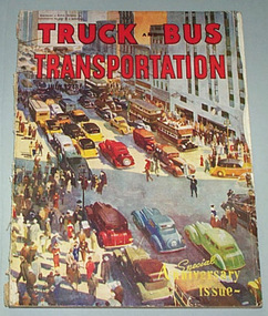
Magazine, Shennan Publishing & Publicity, "Special 12th Anniversary Issue" - Truck & Bus Transportation - July 1948, 1948
... cable cars. Tracing the development of the Motor Bus in Aust. - p73. Australian Transport Administrations - whose , photos, responsibilities, liquid fuel control (petrol rationing), Australian Road Transport Associations, executives etc. - pl16 onwards Ansett organisation - p 1 72 onwards ...cable cars. Tracing the development of the Motor Bus in Aust. - p73. Australian Transport Administrations - whose , photos, responsibilities, liquid fuel control (petrol rationing), Australian Road Transport Associations, executives etc. - pl16 onwards Ansett organisation - p 1 72 onwards "Special 12th Anniversary Issue" - Truck & Bus Transportation - July 1948 Magazine Shennan Publishing & Publicity ...Yields information about Australian transport history, transport at the time of publication and the development of buses and the Ansett organisation.Large format 208 page , July 1948 issue of Truck and Bus Transportation with colour cover, fold out and advertisements, colour printing, articles on buses, trucks, cable trams, Australian Transport, personnel in industry, Ansett, executives - special 12 the anniversary issue. See photocopy of title and contents pages with item notes. Notes on Truck & Bus Transportation - Special Anniversary Issue - July 1948, with particular relevance to BTM Archives Advertisements: White Bus Co - similarity to the US PCC Tram - inside front cover Ansett's and Ansair - p131 AC buses - p162 Articles: Has Australia's Railways Reach the Doldrums? - p38 Modem Street Transit Authorities Announce Development Policy - p42 (includes photos of Sydney, Adelaide Glenelg H class, Bourke St, trams etc, being replaced by buses) These were the Events that made our Headlines (war years - photos included - p61 Riding the Rattlers behind Horses, Ropes and Billies - cable trams, horse and steam trams p66. - demise of Melbourne cable cars. Tracing the development of the Motor Bus in Aust. - p73. Australian Transport Administrations - whose , photos, responsibilities, liquid fuel control (petrol rationing), Australian Road Transport Associations, executives etc. - pl16 onwards Ansett organisation - p 1 72 onwards trams, tramways, trucks, buses, cable trams, road transport