Showing 31 items matching "power circuits"
-
 Kiewa Valley Historical Society
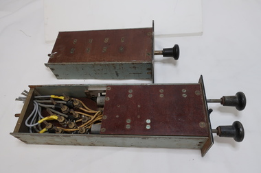
Electrical Equipment - Relays
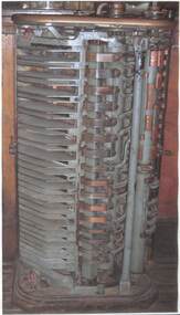
... power circuits... by an independent low-power signal, or where several circuits must be controlled by one signal....The relays were from a Kiewa Hydro Power Station control panel. power circuits electrical equipment electric power control power relays power station circuit breaker One has a plaque attached. ...Protective relays are one of the critical components of the elctrical power grid that serve to detect defective equipment or other dangerous or intolerable conditions and can either initiate or permit switching or simply provide an alarm to provide an alarm to provide a safer, more reliable delivery system. Used in power stations. The function of relay is to quickly remove from service any equipment that might suffer damage or otherwise affect the operation of the system. Relays protect the electrical system in 2 ways: Prevent failure or damage to electrical systems. Mitigate the effects of failure when it occurs. Switches that control other switches. Relays are used where it is necessary to control a circuit by an independent low-power signal, or where several circuits must be controlled by one signal.Used by the State Electricity Commission of Victoria for the Kiewa Hydro Electric Scheme in the power stations. Manually operated by remote control for an external circuit breaker. The relays were from a Kiewa Hydro Power Station control panel.Collection of black metal rectangular boxes (heavy) containing electrical wires forming a circuit. The longer, narrower rectangles have a bakelite knob at one end. Some of the boxes have one side of clear perspex and another has all sides of clear perspex. One is labelled "group relay". Another has windows with labels eg. 'turbine overspeed' 'emergency trip' and one has 3 steel knobs. - with 'stop', 'start'. One box is larger than the rest and has clear perspex side showing 'overcurrent relay' and workings.One has a plaque attached. Manufacture: "The English Co. Ltd. Londonpower circuits, electrical equipment, electric power control, power relays, power station, circuit breaker -
 The Ed Muirhead Physics Museum
Vertex V170 Hard Drive, 20th Century
... Computer hard drive with exposed power board, circuits and interfaces. Model V.170....USA / WARNING / HANDLING PROCEDURE' Computer hard drive with exposed power board, circuits and interfaces. Model V.170. ...Computer hard drive with exposed power board, circuits and interfaces. Model V.170.Label on back: 'VERTEX PERIPHERALS / MILPITAS, CA. USA / WARNING / HANDLING PROCEDURE'vertex, hard drive, v 170, computer peripherals, computer equipment, hardware, california -
 Flagstaff Hill Maritime Museum and Village
Equipment - Power Supply, 1920s
... Power supply, portable, electric; circuits can be Parallel or Series. ...Flagstaff Hill Flagstaff Hill Maritime Museum and Village Warrnambool Maritime Museum Maritime Village Great Ocean Road portable power supply power supply battery box battery communication radio portable radio battery powered radio electronic instrument Stamped into the vertical panel are "parallel", "P", "H", "SERIES", CAVERTY", "LIGHT" :WEAK", "CHARGING" Power supply, portable, electric; circuits can be Parallel or Series. ...The box is cleverly designed to give quick access to the parts inside, having a lift-up lid and a pull-down front. The components within appear to be a portable radio, power supply or power converter with batteries and a charger. The attached leather strap makes the equipment easily portable. The portable power supply is significant for representing part of the evolutionary change in communications. The unit connects the use of power and radio for communication with the ability to save the power in power packs or batteries, or to convert the power from one form to another.Power supply, portable, electric; circuits can be Parallel or Series. Batteries (6) fitted into a square wooden box. Box has two catches to secure the lid and two catches to secure the drop-down front. Holes have been drilled around the edges of the lid and the top of the base. Inside the front panel are two copper coils, switches and connectors. Leather carry strap attached. Stamped into the vertical panel are "parallel", "P", "H", "SERIES", CAVERTY", "LIGHT" :WEAK", "CHARGING" Stamped into the vertical panel are "parallel", "P", "H", "SERIES", CAVERTY", "LIGHT" :WEAK", "CHARGING" flagstaff hill, flagstaff hill maritime museum and village, warrnambool, maritime museum, maritime village, great ocean road, portable power supply, power supply, battery box, battery, communication, radio, portable radio, battery powered radio, electronic instrument -
 Monash University Museum of Computing History
Ferranti Sirius mainframe computer, 1961
... The Central Processing Unit is a floor-standing unit which contains the computer circuits, power supplies and has a decimal digit display panel and a normal clock. ...The Central Processing Unit is a floor-standing unit which contains the computer circuits, power supplies and has a decimal digit display panel and a normal clock. ...The Ferranti Sirius is an electronic second-generation transistor computer and is one of three remaining examples of this machine left in the world. It was an important addition to the computing facilities at Monash University in the early 1960s and provided access for computer programming and research for many early computer professionals, academics and teachers. The Ferranti Sirius computer was built in a period of rapid growth in computing technology. The first stored program computers appeared in the late 1940s and used individual designs with valve technology. By the mid-1950s valve technology was replaced by transistors and the first mass produced commercial computers became available. The Ferranti Sirius was announced in 1959 and offered a “small” academic computer. It was designed and built by the English company Ferranti Ltd and sold through a local office of the company in Melbourne. The Sirius was manufactured at the Ferranti Ltd.’s West Gorton, England factory from 1959 to 1963 and, in all, the company produced probably 22 installations although only 16 were actually recorded as sold; this included one at Ferranti’s Bureau in London and one at Ferranti’s Melbourne Bureau. Only 7 were exported and 4 of these 7 were located in Melbourne, Australia. All four were associated with computing at Monash University – the Sirius in the MMoCH collection was purchased by Monash University in 1962, a smaller Ferranti Sirius was used on the Caulfield campus (prior to amalgamation with Monash University) from 1963, the Ferranti company had its own Ferranti Sirius initially temporarily installed at Clayton campus in 1962 and then placed in their office in Queens Road, Melbourne. A fourth computer was purchased by ICIANZ (now Orica) in 1962 and was transferred to Clayton campus in 1967. Only two of these Melbourne examples have survived; one in the MMoCH collection and one at Museums Victoria. There is an example of the Ferranti Sirius in the Science Museum Group collection in the UK as well. The Ferranti Sirius in the MMoCH collection was the first computer purchased by Monash University and it was shipped to Australia to be installed by November 1962. The University had a similar model computer on loan from Ferranti Ltd during the first part of the year and it was returned to the office of the company in Queens Road, Melbourne once the University’s own machine was installed. The computer was placed on site at Clayton campus, Monash University. The computer operated from 1962 until 1972 when it was officially decommissioned. The Ferranti Sirius was sold to Mr Paul Stewart in late 1974 and removed from Monash University. Mr Stewart later donated the computer back to the University in 1988 and it was transferred to the collection of the Monash Museum of Computing History after 2001. The Ferranti Sirius is an electronic second-generation transistor computer and is one of three remaining examples of this machine left in the world. It was an important addition to the computing facilities at Monash University in the early 1960s and provided access for computer programming and research for many early computer professionals, academics and teachers. The Ferranti Sirius is of scientific (technological) significance as one of the early transistor digital computers that transitioned computing from first-generation valve computers to second generation commercial installations. This example of the Sirius is of historical significance in its role as a part of the Computer Centre, Clayton campus, Monash University which provided computing facilities in Melbourne in the early 1960s when there were few installations available for academic, administrative and commercial users. Staff and students were able to undertake investigative research and learn programming techniques. The Computer Centre encouraged the use of the computer across all disciplines and this provided the base to establish computer science as a subject offering and, later, a new department in the University. This growth in computer education eventually culminated in the establishment of the Faculty of Information Technology, Monash University. The Ferranti Sirius in the collection at Monash Museum of Computing History has a main unit with a CPU and memory combined with input/output equipment and one extra cabinet of memory. The Central Processing Unit is a floor-standing unit which contains the computer circuits, power supplies and has a decimal digit display panel and a normal clock. A moveable control panel is placed in front of the Unit (Currently set on a recreated desk/filing cabinet support in the display). The Sirius base unit uses acoustic delay line memory with 1000 word store. An additional 3000 word memory cabinet is set adjacent to the CPU and can be connected to increase the memory. The computer is supported by a range of input/output devices. There is a Ferranti Paper tape reader, located on desk in front of CPU. Red label on front “Ferranti tape reader. Type TR 5. Serial No. 477”. Adjacent to the CPU is a set of Simplified tape editing equipment in three pieces which includes a (1) Table unit with switches on front face. Metal tag on reverse reads “Creed & Co. Model No. S4060. Serial No. 1457. Original Customers Marking GRP7 V706”. The table has a numbered internal tag “Table Serial No. 198579. (2)Creed teletype set on table unit. Metal tag on reverse “Creed & Co. Model No. 75RPR K4M4. Serial No. 5897 Made in England”. (3)Creed paper tape reader set on table unit. This set of equipment could read paper tape and print it, or copy paper tape while allowing it to be edited, or allow a programmer or data preparation person to type and punch a new program or data. It has no electrical connection to the computer. Paper tapes were usually torn off and carried across to the computer. There is also another table unit with switches on front face and changeable setting switch on front right side which holds a Ferranti Westrex paper tape punch set. Label on reverse “Teletype Code BRPE11” This was the Computer’s only output device. BRPE-11 is a teletype model number. -
 Kiewa Valley Historical Society
Photograph - Folder of Photographs – Photocopied set of black and white photographs (pages 39 - 48) from the display folder put together by KVHS to document life on the Kiewa Valley Hydro-electric Scheme
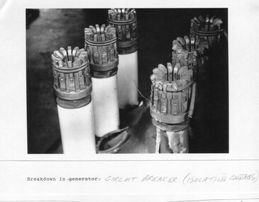
... Large A3 size spiral bound display folder containing photocopied black and white photographs of various aspects of the early days of the Kiewa Valley Hydro-electric scheme including equipment, various work sites and photographs of workers and their families. 1-Breakdown in Circuit Breaker (Isolating Contacts) 2-Big Hill Bench- Site of No 5 Devlopment 3-No 1 Power Station 4-No 1 Pipeline, Anchor No 8 5-Push Dozing-RD8 Tractor 6- Tractor and driver at work 7- Workmen in unnamed tunnel 8- Front page of Journal of SECV Vol 15. ...It is a circuit breaker Signed Ron White Ron was the Principal Hydro Engineer of the SEC Kiewa Scheme Page number 39 2-Big Hill Bench – Site of No. 5 Development (abandoned) Page number 40 3-No 1 Power Station Page number 41 4-No. 1 Pipeline, Anchor No. 8 Page number 42 5-Push Dozing – RD8 Tractor, 12 cubic yard Carryall and FD Cletrac Tractor Page number 43 6-No marking Page number 44 7-No marking Page number 45 8-Journal of State Electricity Commission of Victoria SEC Vol 15 No… April-May, 19… No 1 Pipeline-A view from McKay Portal G Hempenstall and D Sutton stiffening pipe section for transport during construction (….indicates missing text) Page Number 46 9-Rocky Valley Dam Core Wall Page number 47 10-No markings Page number 48 ...Mount Beauty, and to a lesser extent Bogong, are among these places. secv; kiewa hydro electric scheme; construction area; power stations; reservoirs; aqueduct; mt beauty; bogong 1-Breakdown in (generator) Circuit Breaker (Isolating Contacts) Handwritten underneath (This is not a picture of any part of a generator. ...Although the Kiewa Hydro-Electric Scheme was first proposed in 1911, construction did not commence until 1938. As part of the push to cut electricity costs and diversify supply, the Victorian Government (circa 1930) initiated the conversion from primarily brown coal supply to hydro – electricity. Field investigations during the 1940’s resulted in a new proposal for a scheme that had more than double the capacity of the 1938 scheme. The Kiewa Hydroelectric Scheme became the largest scheme of its kind in the State Of Victoria and the second largest scheme in Australia. The number of personnel involved in the planning and construction of the scheme increased dramatically. During the late 1940’s, most activity centered around the construction of the West Kiewa Power Station, Rocky Valley Reservoir, McKay Creek Power Station and the Bogong Creek Aqueduct.A common thread across all the larger hydro scheme constructions was the need for workers, both qualified and unqualified who came from around the world seeking a new life for themselves and their families. New accommodation and facilities were required for the army of workers engaged in construction in often remote and wild areas. The SEC had a high demand for timber, and set up the first of a number of sawmills at Bogong Creek in 1939 and set up the first hardwood logging in the headwaters of the Kiewa River. These new ‘towns’ such as Mt Beauty and Bogong, survived, serving the needs of operational personnel and their families, and expanding with growth of new industries. Mount Beauty, and to a lesser extent Bogong, are among these places. Large A3 size spiral bound display folder containing photocopied black and white photographs of various aspects of the early days of the Kiewa Valley Hydro-electric scheme including equipment, various work sites and photographs of workers and their families. 1-Breakdown in Circuit Breaker (Isolating Contacts) 2-Big Hill Bench- Site of No 5 Devlopment 3-No 1 Power Station 4-No 1 Pipeline, Anchor No 8 5-Push Dozing-RD8 Tractor 6- Tractor and driver at work 7- Workmen in unnamed tunnel 8- Front page of Journal of SECV Vol 15. Photograph of No 1 pipeline viewed from McKay Portal 9-Rocky Valley Dam Core Wall 10-Workmen working inside tunnel loading rocks into a rail truck. 1-Breakdown in (generator) Circuit Breaker (Isolating Contacts) Handwritten underneath (This is not a picture of any part of a generator. It is a circuit breaker Signed Ron White Ron was the Principal Hydro Engineer of the SEC Kiewa Scheme Page number 39 2-Big Hill Bench – Site of No. 5 Development (abandoned) Page number 40 3-No 1 Power Station Page number 41 4-No. 1 Pipeline, Anchor No. 8 Page number 42 5-Push Dozing – RD8 Tractor, 12 cubic yard Carryall and FD Cletrac Tractor Page number 43 6-No marking Page number 44 7-No marking Page number 45 8-Journal of State Electricity Commission of Victoria SEC Vol 15 No… April-May, 19… No 1 Pipeline-A view from McKay Portal G Hempenstall and D Sutton stiffening pipe section for transport during construction (….indicates missing text) Page Number 46 9-Rocky Valley Dam Core Wall Page number 47 10-No markings Page number 48 secv; kiewa hydro electric scheme; construction area; power stations; reservoirs; aqueduct; mt beauty; bogong -
 Kiewa Valley Historical Society
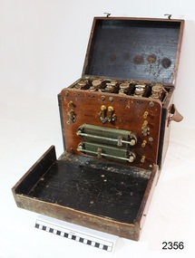
Electric Megger (Insulation Tester) and its case
... circuit breaker, when switched on, then it must be checked electrically before any more use. Following the repair of the faulty item a megger would be used to check if either of the AC 240volt plugs leads were touching the metal case (earth). The output leads of the megger would be connected with one to the earth (metal case) and the other to each of the power...circuit breaker, when switched on, then it must be checked electrically before any more use. Following the repair of the faulty item a megger would be used to check if either of the AC 240volt plugs leads were touching the metal case (earth). The output leads of the megger would be connected with one to the earth (metal case) and the other to each of the power ...Megger as the device was called, is in fact its brand name. It is a device that supplies a DC (direct current as per car batteries) voltage to enable testing of electrical apparatus. This particular device produces 250volts DC when the handle is turned vigorously. If an electrical device, such as a kettle or toaster, blew a fuse or tripped a circuit breaker, when switched on, then it must be checked electrically before any more use. Following the repair of the faulty item a megger would be used to check if either of the AC 240volt plugs leads were touching the metal case (earth). The output leads of the megger would be connected with one to the earth (metal case) and the other to each of the power connections in turn. A good megger reading of 50,000 ohms (resistance) would enable the device to be returned to service. A reading of zero ohms resistance would mean that it would again blow a fuse, and was therefore unsafe to use. In the electrical industry e.g. the former State Electricity Commission, a megger would be used to test lots of similar item in sequence. Because of the vigorous job of winding the handle, two persons were often used to save time. One would crank madly whilst the other shifted the leads. This particular megger is of a small voltage, but other meggers are bigger and have a few ranges of DC voltages able to be selected. The optimal megger for large Generating machines was motor driven megger. This was applied to the device being tested for a duration of approximately 30 minutes with reading of the resistance taken at regular intervals.All equipment belonging to the State Electricity Commission of Victoria was labelled with a metal plaque attached to it. The SECV constructed the Kiewa Hydro Electric Scheme in the Upper Kiewa Valley and on the Bogong High Plains. The scheme began in 1938 and finished in 1961 when this megger was used and also possibly later as the SECV remained to maintain and operate the Scheme. This megger is of significance in relation to the advancement of technology.A rectangular box in dark brown bakerlite casing. It has an agent's plaque fixed to the left of the face and on the right is the marker's recessed stamp. In the middle in a transparent window so the level of ohms can be read. The front also has two recessed fixing knobs in black. On one side is a crank handle with a knob that lifts up and is turned vigorously to create the voltage. The back has four recessed screws and four small leather pads. There is a hole on each side to insert wires. There are two copper insulated wires. The SECV Plaque states: State/Electricity Commission/of/Victoria/ Electrical Engineer's Section/ No.1747 The Agent's Plaque states: H. Rowe & Co. Pty Ltd/Melbourne & Sydney/Sole Agents/in Australia for/Evershed & Vignoles Ltd Maker's states: 500 volts/Megger/Regd Trade Mark/Made in England/Patent No/400728electrical meters, electrical equipment, fuses, safety, state electricity commission of victoria, mt beauty, bogong village -
 Kiewa Valley Historical Society
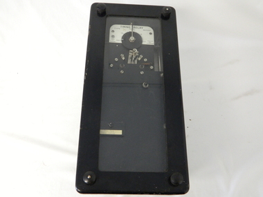
Timer Mechanical, Circa 1950
... circuit operate in a sequence control system. The sequences that use these timers are when starting and stopping Hydro Generators. They check that the machine has connected to the power system grid before 20 minutes duration. ...circuit operate in a sequence control system. The sequences that use these timers are when starting and stopping Hydro Generators. They check that the machine has connected to the power system grid before 20 minutes duration. ...This Timing Relay is quite a large (industrial type) apparatus. The Timer is started by having a voltage of 250 volts direct current (as supplied by batteries). A DC motor then rotates driving into a clockwork mechanism, the output of which is an arm rotating at the same speed as a minute hand on a clock. Attached to this arm is a mercury switch which tips and makes an electrical circuit operate in a sequence control system. The sequences that use these timers are when starting and stopping Hydro Generators. They check that the machine has connected to the power system grid before 20 minutes duration. Brakes must go on for a set time when shutting down a generator slowing at the right speed as measured by this apparatus. These generators are powered by the hydro force of "stored" water at a higher altitude. The establishment of both the NSW and Victorian Hydro schemes was achieved from the mid 1900's to the 1960's. At this point in time the need for additional power sources to quench both an industrial and domestic demand for electricity was purely an economic and not and environmental (carbon reduction) factor. This Timing Relay apparatus is very significant to the Kiewa Valley as its use was introduced during the Kiewa Hydro Scheme. Although only a relay apparatus, it was however part of the explosion of human resources into the valley. This influx of population transformed the region from that of a basically quiet rural region to one which evolved into both an industrial and a larger residential community. This evolution in the valley created a change, not only in the "physical" landscape but also the socio-economic expansion which permitted other "tourist" based industries into the valley. This Hydro Scheme was instigated by "the Government of the day" as a bold move and was the major force behind the acceptance of World War II refugee and "technical" workforce. Inclusion of skilled and unskilled migration into the Australian environment was of a higher priority than a selective quota system of later years.. Although this mass "invasion" of workers with families was thought of in some circles as intrusive, the expansion of population post war years and its integration into the Australian rural sector, produced the multi- lingual, multi-cultural diversity of later years.sec vic kiewa hydro scheme, alternate energy supplies, alpine population growth -
 Kiewa Valley Historical Society
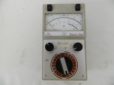
Meter Multi General Purpose, circa mid to late 1900's
... circuit. During this time period, high quality testing instruments were either sourced from Europe or England. This particular meter was manufactured in the Netherlands. This type of "old" analogue meter was replaced by digital meters whose electronic components are a fraction of the size of the older analogue ones. This analog General Purpose multi-meter is quite a large (for handheld mobile) apparatus which permits the easy monitoring of electrical variations within the large SEC Victoria Hydro Scheme's electrical generators. These generators are powered ...This general purpose Multi-meter was manufactured after 1950 and used by the SEC Vic (Kiewa Hydro Electricity Scheme) from that date until late 1900's. It was used to measure very small voltages associated with the operation of the various Hydro Generators. The readings were able to be shown by the resistor in use in the current circuit. During this time period, high quality testing instruments were either sourced from Europe or England. This particular meter was manufactured in the Netherlands. This type of "old" analogue meter was replaced by digital meters whose electronic components are a fraction of the size of the older analogue ones.This analog General Purpose multi-meter is quite a large (for handheld mobile) apparatus which permits the easy monitoring of electrical variations within the large SEC Victoria Hydro Scheme's electrical generators. These generators are powered by the hydro force of "stored" water at a higher altitude. The establishment of both the NSW and Victorian Hydro schemes was achieved from the mid 1900's to the 1960's. At this point in time the need for additional power sources to quench both an industrial and domestic demand for electricity was purely an economic and not and environmental (carbon reduction) factor. This hydro scheme was instigated by "the Government of the day" as a bold move and was the major force of the World War II refugee and "technical" workforce inclusion of skilled and unskilled migration into the Australian environment. Although this mass "invasion" of workers with families was thought of in some circles as intrusive, the expansion of population post war years and its integration into the Australian rural sector, produced the multi- lingual multi-cultural diversity of later years.This General Purpose Multimeter is an analogue meter i.e. it has a needle arm that moves across a scale of divisions. This is a large(hand held) device due to the mechanical movement system within and the large size of its electronic components of its circuitry.There are two black bake-lite push buttons operating the wire inserts Positive/negative leads at the top. The meter (protected with a glass window) has clearly marked graduations (top - volts, bottom amperes). Below this are two bake-lite dials (left "potentiometer the right one measuring range selector). Below this is a "dial" switch to input the desired resistance measuring range "V" Front "H&B ELIMA" and to the right Elavi 15n. 0n the front side is a label "STATE ELECTRICITY COMMISSION OF VICTORIA TRANSMISSION DEPT E.C.No." On the bottom of the base is a stenciled layout of the battery "layout" including the fuse . The information notice is presented in five languages starting with German, English,French, Italian, Spanish and Dutchsec vic kiewa hydro scheme, alternate energy supplies, alpine population growth -
 Kiewa Valley Historical Society
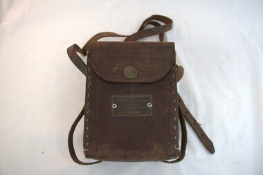
Case for G.P. Multimeter, Circa 1950
... circuit. During this time period, high quality testing instruments were either sourced from Europe or England. This particular carry case was manufactured in the Netherlands. This carry case for an analog General Purpose multi-meter which is quite a large (for a handheld mobile) apparatus.The bag however permits the easy monitoring of electrical variations within the large SEC Victoria Hydro Scheme's electrical generators. These generators are powered ...This leather case holder for a general purpose Multi-meter( KVHS 0307 (A)) was manufactured after 1950 and used by the SEC Vic (Kiewa Hydro Electricity Scheme) from that date until late 1900's. It was used to measure very small voltages associated with the operation of the various Hydro Generators. The readings were able to be shown by the resistor in use in the current circuit. During this time period, high quality testing instruments were either sourced from Europe or England. This particular carry case was manufactured in the Netherlands. This carry case for an analog General Purpose multi-meter which is quite a large (for a handheld mobile) apparatus.The bag however permits the easy monitoring of electrical variations within the large SEC Victoria Hydro Scheme's electrical generators. These generators are powered by the hydro force of "stored" water at a higher altitude. The establishment of both the NSW and Victorian Hydro schemes was achieved from the mid 1900's to the 1960's. At this point in time the need for additional power sources to quench both an industrial and domestic demand for electricity was purely an economic and not and environmental (carbon reduction) factor. This hydro scheme was instigated by "the Government of the day" as a bold move and was the major force of the World War II refugee and "technical" workforce inclusion of skilled and unskilled migration into the Australian environment. Although this mass "invasion" of workers with families was thought of in some circles as intrusive, the expansion of population post war years and its integration into the Australian rural sector, produced the multi- lingual multi-cultural diversity of later years.This leather case is to provide protection for this mobile G.P. Multimeter, therefore it is made from thick leather. It has a carrying strap from a thick "D" chromed link. This link is fastened to the main cover by a looped leather strip with a black coloured rivet. All the fasteners are either chrome or black coloured rivets. The front, which when opened back exposes fully the inside of the case. It is clip fastened to the lower section of the front piece which also can be pushed back allowing the meter to be removed from the frontal position. There is a strip retaining strap slightly higher from the mid point. This is fasted by a black press stud. There are two "L" shaped tin protrusions allowing the meter to slide only down the case until it rests on these shelves. This provides for an empty space for minimal storage,.On the front bottom and below the clasp is a tag "STATE ELECTRICITY COMMISSION OF VICTORIA TRANSMISSION DEPT."sec vic kiewa hydro scheme, alternate energy supplies, alpine population growth -
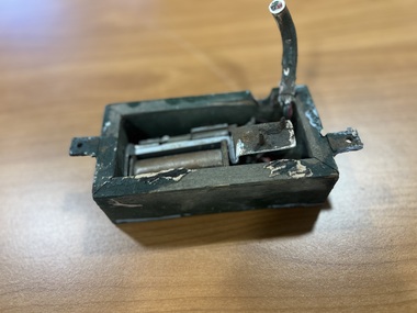
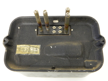 Kiewa Valley Historical Society
Relay Protection Instrument, Circa 1950's
... The front glass enclosed meter and recorder allows for the identification and automatic disconnection of any faulty equipment connected to the main power generator. This equipment acts similarly to a modern day circuit breaker found on the electrical circuit boards of residential homes....The front glass enclosed meter and recorder allows for the identification and automatic disconnection of any faulty equipment connected to the main power generator. This equipment acts similarly to a modern day circuit breaker found on the electrical circuit boards of residential homes. ...This protection relay apparatus (a large electrical fuse), which permits the easy monitoring and disconnection of faulty electrical apparatus connected to the large SEC Victoria Hydro Scheme's electrical power producing generators. These generators are powered by the hydro force of "stored" water at a higher altitude. The establishment of both the NSW and Victorian Hydro Schemes was achieved from the early 1900's to the 1960's. At this point in time the need for additional power sources to quench both an industrial and domestic demand for electricity was purely an economic and not and environmental (carbon reduction) factor. This hydro scheme was instigated by "the Government of the day" as a bold move and was the major force of the World War II refugee and "technical" workforce inclusion of skilled and unskilled migration into the Australian environment. Although this mass "invasion" of workers with families was thought of in some circles as intrusive, the expansion of population post war years and its integration into the Australian rural sector, produced the multi- lingual multi-cultural diversity of later years.This protection relay is very significant to the Kiewa Valley as its use was introduced during the Kiewa Hydro Scheme. Although only a small apparatus it was part of the explosion of human resources into the valley. This influx of population transformed the region from that of a basically quiet rural region to one which evolved into both an industrial and a larger residential community. This evolution in the valley created a change, not only in the "physical" landscape but also the socio-economic expansion which permitted other "tourist" based industries into the valley.This protection relay unit has a black painted metal shell with four copper enclosed "prongs" fastened to the rear of the housing(from a bake-lite plate) . Between these "prongs" are four "empty" points allowing additional "screw on" bases. The front glass enclosed meter and recorder allows for the identification and automatic disconnection of any faulty equipment connected to the main power generator. This equipment acts similarly to a modern day circuit breaker found on the electrical circuit boards of residential homes.On the top section of the front panel "ASEA" to the left "Made in Sweden" and to the right "Frabrique en Suede" below this "RIS" below this a graph and next to it two columns of numbers and a pointer for each setkiewa hydro electricity scheme, victorian state electricity commission, relays, generators -
 Greensborough Historical Society
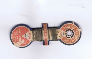
Electric Fuse, Copper Fuse Wire, 1930s
... Greensborough Historical Society 34A Glenauburn Road Lower Plenty Lower Plenty melbourne Used in pre-circuit breaker domestic electric fuse boxes fuse wire electricity "Hang on your fuse box", "Use one strand only", "Made in Australia", "Best tinned copper wire" 8 amp (light) and 15 amp (power) tinned copper wire wound onto cardboard holder, printed in red and blue Copper Fuse Wire Electric Fuse ...Used in pre-circuit breaker domestic electric fuse boxes8 amp (light) and 15 amp (power) tinned copper wire wound onto cardboard holder, printed in red and blue "Hang on your fuse box", "Use one strand only", "Made in Australia", "Best tinned copper wire"fuse wire, electricity -
 The Paynesville Maritime Museum
Poster
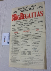
... The annual regatta circuit of the Gippsland Lakes was very popular with holiday makers and racing would typically attract 3000 spectators to watch. Races were held for both sail and power...The Paynesville Maritime Museum Raymond Street Paynesville gippsland The annual regatta circuit of the Gippsland Lakes was very popular with holiday makers and racing would typically attract 3000 spectators to watch. Races were held for both sail and power ...The annual regatta circuit of the Gippsland Lakes was very popular with holiday makers and racing would typically attract 3000 spectators to watch. Races were held for both sail and power boatsAdvertising poster on thick paper -
 Federation University Historical Collection
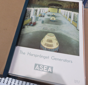
Magazine, ASEA magazines, 1953/58, 1953 to 1958
... power stations...voltage control...electrohydraulic governor for water turbines...high voltage dc transmission...oil-minimum contraction circuit...Barker Library (top floor) Mount Helen goldfields collected by Ballarat School of Mines Principal G.H.Beanland electrical engineering generators graham beanland power stations voltage control electrohydraulic governor for water turbines high voltage dc transmission oil-minimum contraction circuit-breakers lightening arresters air-blast circuit breakers testing circuit breakers closing mechanisms for high voltage circuit-breakers outdoor isolators series capacitors capacitor voltage transformers guide to current transformers routine testing of power tranformers generator Magazines bound in ASEA folder, blue spine and black cloth boards ASEA magazines, 1953/58 Magazine ...collected by Ballarat School of Mines Principal G.H.BeanlandMagazines bound in ASEA folder, blue spine and black cloth boardselectrical engineering, generators, graham beanland, power stations, voltage control, electrohydraulic governor for water turbines, high voltage dc transmission, oil-minimum contraction circuit-breakers, lightening arresters, air-blast circuit breakers, testing circuit breakers, closing mechanisms for high voltage circuit-breakers, outdoor isolators, series capacitors, capacitor voltage transformers, guide to current transformers, routine testing of power tranformers, generator -
 Federation University Historical Collection
Scientific Instument, Capacitor
... power) farad. The microfarad is a moderate unit of capacitance. In utility alternating-current (AC) and audio-frequency (AF) circuits, capacitors with values on the order of 1 µF or more are common. ...power) farad. The microfarad is a moderate unit of capacitance. In utility alternating-current (AC) and audio-frequency (AF) circuits, capacitors with values on the order of 1 µF or more are common. ...DEFINITION microfarad Posted by: Margaret Rouse WhatIs.com Contributor(s): Kenda, Jack Clements The microfarad (symbolized µF) is a unit of capacitance, equivalent to 0.000001 (10 to the -6th power) farad. The microfarad is a moderate unit of capacitance. In utility alternating-current (AC) and audio-frequency (AF) circuits, capacitors with values on the order of 1 µF or more are common. At radio frequencies (RF), a smaller unit, the picofarad (pF), is often used. This unit is equal to .000000000001 (10^-12) µF. In RF scenarios, capacitances range from about 1 pF to 1,000 pF in tuned circuits, and from about 0.001 µF to 0.1 µF for blocking and bypassing. At audio frequencies (AF), capacitances range from about 0.1 µF to 100 µF. In power-supply filters, capacitances can be as high as 10,000 µF. Capacitor, 1/3 M.F.D. (microfarad) within wooden insulating box. Two terminal posts set in an insulating box. Maker's name and place 1/3 M.F.D No. 34402scientific instrument, capacitor, electrical engineering, laboratory -
 Ballarat Tramway Museum
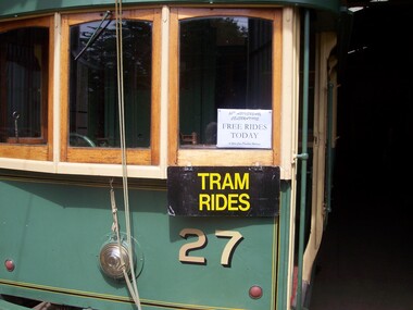
Photograph - Digital image Set of 25, Warren Doubleday, 26/12/2004 12:00:00 AM
... Set of 21 Digital Images of the recommencement or reopening of tram services following the reconstruction of the power supply and substation on 26/12/2004. .1 - Sign announcing free rides today in the front of No. 27 .2 - Peter Winspur and Garry Wood showing Peter the process for turning the power on .3 - ditto .4 - closing the Circuit Breaker .5 - 27 runs across Wendouree Parade .6 - 27 leaves the depot .7 - Peter Winspur removes the sign on the pole saying we were not running .8 - 27 in Wendouree Parade .9 - Carolyn Cleak removing a sign .10 - Placing signs and turning the pole at Carlton St .11 - Carlton St and waiting passengers .12 - Pole sign and bicycle warning sign re tram tracks .13 - Sam Boon and band at Gardens Loop .14 - ditto .15 - ditto .16 - Happy passengers .17 - Richard Gilbert - reopening speech. .18 - No. 26 and happy passengers .19 - 27 and 26 at the loop .20 - No. 26 at the loop, with passengers and the band. .21 - as for 19...Ballarat Tramway Museum South Gardens Reserve Wendouree Parade Ballarat Ballarat goldfields Trams tramways BTM Substation Wendouree Parade Reopening Carlton St Gardens Loop tram 27 tram 26 Set of 21 Digital Images of the recommencement or reopening of tram services following the reconstruction of the power supply and substation on 26/12/2004. .1 - Sign announcing free rides today in the front of No. 27 .2 - Peter Winspur and Garry Wood showing Peter the process for turning the power on .3 - ditto .4 - closing the Circuit Breaker .5 - 27 runs across Wendouree Parade .6 - 27 leaves the depot .7 - Peter Winspur removes the sign on the pole saying we were not running .8 - 27 in Wendouree Parade .9 - Carolyn Cleak removing a sign .10 - Placing signs and turning the pole at Carlton St .11 - Carlton St and waiting passengers .12 - Pole sign and bicycle warning sign re tram tracks .13 - Sam Boon and band at Gardens Loop .14 - ditto .15 - ditto .16 - Happy passengers .17 - Richard Gilbert - reopening speech. .18 - No. 26 and happy passengers .19 - 27 and 26 at the loop .20 - No. 26 at the loop, with passengers and the band. .21 - as for 19 Photograph Digital image Set of 25 Warren Doubleday ...Set of 21 Digital Images of the recommencement or reopening of tram services following the reconstruction of the power supply and substation on 26/12/2004. .1 - Sign announcing free rides today in the front of No. 27 .2 - Peter Winspur and Garry Wood showing Peter the process for turning the power on .3 - ditto .4 - closing the Circuit Breaker .5 - 27 runs across Wendouree Parade .6 - 27 leaves the depot .7 - Peter Winspur removes the sign on the pole saying we were not running .8 - 27 in Wendouree Parade .9 - Carolyn Cleak removing a sign .10 - Placing signs and turning the pole at Carlton St .11 - Carlton St and waiting passengers .12 - Pole sign and bicycle warning sign re tram tracks .13 - Sam Boon and band at Gardens Loop .14 - ditto .15 - ditto .16 - Happy passengers .17 - Richard Gilbert - reopening speech. .18 - No. 26 and happy passengers .19 - 27 and 26 at the loop .20 - No. 26 at the loop, with passengers and the band. .21 - as for 19trams, tramways, btm, substation, wendouree parade, reopening, carlton st, gardens loop, tram 27, tram 26 -
 Ballarat Tramway Museum
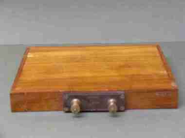
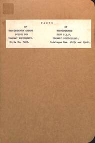
Document - Instruction, Westinghouse Electric & Manufacturing Co, "Parts of Westinghouse Canopy Switch for Tramway Equipments", 10/1906
... It was used to turn on or off the power to a tram. It is not a circuit breaker of the type that are fitted to the Museum's trams....It was used to turn on or off the power to a tram. It is not a circuit breaker of the type that are fitted to the Museum's trams. ...Westinghouse part catalogue B6008 for the "Parts of Westinghouse Canopy Switch for Tramway Equipments" - used for Westinghouse T1F controllers - style Nos. 5437 and 5409, manufactured by Westinghouse Electric & Manufacturing Co. of London and Manchester. Dated Oct. 1906. Lists parts with images and prices. It was used to turn on or off the power to a tram. It is not a circuit breaker of the type that are fitted to the Museum's trams.Yields information about the Westinghouse UK products.Manual or document 8 printed pages centre stapled within card covers.tramways, tramcars, equipment, westinghouse, switches -
 Ballarat Tramway Museum
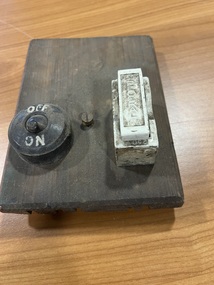
Equipment - Taillight switch and fuse board, State Electricity Commission of Victoria (SECV), c1950
... circuit on a tram. Made by the SECV. The board was located next to the 6V battery that was used to power the tram tail lights when the trolley pole was being reversed under a passenger seat.. ...circuit on a tram. Made by the SECV. The board was located next to the 6V battery that was used to power the tram tail lights when the trolley pole was being reversed under a passenger seat.. ...Item used to switch on or off the red tail lights circuit on a tram. Made by the SECV. The board was located next to the 6V battery that was used to power the tram tail lights when the trolley pole was being reversed under a passenger seat.. Demonstrates an item fitted to a tramcar to switch an external lighting circuit.Softwood wood board with a bakelite two pole switch marked "on" and "off" and a Federal 250V 15A rewireable ceramic fuse attached. Has remnants of cloth covered copper wire on the rear. See item 9024 for an associated drawing."12" in blue pencil.fuse, tram 14, tramcars, tramcar maintenance, electrical switching -
 Ballarat Tramway Museum
Equipment - Taillight relay and box, State Electricity Commission of Victoria (SECV), c1950
... Item used to switch the power for the red tail lights circuit from the trolley pole to the battery circuit when the trolley pole was being reversed and not able to provide power to the internal and external lights. ...Ballarat Tramway Museum South Gardens Reserve Wendouree Parade Ballarat Ballarat goldfields Item used to switch the power for the red tail lights circuit from the trolley pole to the battery circuit when the trolley pole was being reversed and not able to provide power to the internal and external lights. ...Item used to switch the power for the red tail lights circuit from the trolley pole to the battery circuit when the trolley pole was being reversed and not able to provide power to the internal and external lights. Made by the SECV. Salvaged from tram 14 during the project to renew the wiring and electrical arrangements of the tram. The box was located adjacent to the driver's windows and would click when the trolley pole was placed back on the overhead.Demonstrates an item fitted to a tramcar to switch an external battery tail lighting circuit.Wooden box made from softwood with bevelled corners, plywood top painted green containing an 8 Ohm "Post Office" type relay (see reference) fitted with two "break" contacts and associated insulated wiring soldered to the relevant contacts. See item 9024 for an associated drawing. Two examples held.fuse, tram 14, tramcars, tramcar maintenance, electrical switching -
 Ballarat Tramway Museum
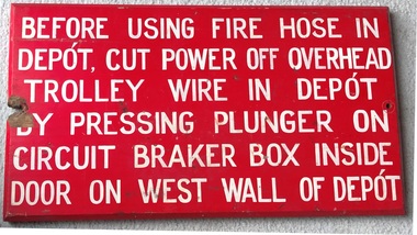
Sign - Emergency Response - SEC Tram Depot Ballarat
... Set of two wooden signs, with chamfered edges, red background with white painted letters, advising SEC Ballarat Depot workers or Firefighters that the power had to be cut to the Trolley Wire prior to using a fire hose in the depot building. An emergency button was provided in a circuit breaker box for this purpose. ...Demonstrates and provides information to Depot workers and Fire Fighters that the power had to be turned off to the Trolley Wire inside the depot using an emergency circuit breaker and where this equipment was provided before using a fire hose. ...Possibly made by local SEC Staff for the refurbished Ballarat Tram depot during the mid 1930's. Note the spelling of Depot with the accent.Demonstrates and provides information to Depot workers and Fire Fighters that the power had to be turned off to the Trolley Wire inside the depot using an emergency circuit breaker and where this equipment was provided before using a fire hose.Set of two wooden signs, with chamfered edges, red background with white painted letters, advising SEC Ballarat Depot workers or Firefighters that the power had to be cut to the Trolley Wire prior to using a fire hose in the depot building. An emergency button was provided in a circuit breaker box for this purpose. Rear has been primed with a pink primer. .1 - complete sign .2 - bottom section broken offtramways, ballarat, signs, emergencies, tramway power, fire fighting, safety -
 Ballarat Tramway Museum
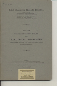
Book, British Engineering Standards Association, "Electrical Machinery excluding motors for traction purposes", 1927-1939
... Ballarat Tramway Museum South Gardens Reserve Wendouree Parade Ballarat Ballarat goldfields Trams tramways Power Station Standards Materials Electrical Systems .1 - Book - 56 pages + grey covers, side stapled, issued by the British Engineering Standards Committee "Electrical Machinery excluding motors for traction purposes", No. 72-1917, September 1917. Has "Commonwealth Engineer" label along the bottom edge. .2 - Book 28 pages - light grey covers, side stapled, issued by the British Engineering Standards Association, "Insulating oils for use in Transformers, oil switches and circuit breakers" No. 148-1923, April 1923. ....1 - Book - 56 pages + grey covers, side stapled, issued by the British Engineering Standards Committee "Electrical Machinery excluding motors for traction purposes", No. 72-1917, September 1917. Has "Commonwealth Engineer" label along the bottom edge. .2 - Book 28 pages - light grey covers, side stapled, issued by the British Engineering Standards Association, "Insulating oils for use in Transformers, oil switches and circuit breakers" No. 148-1923, April 1923. Has a Tait Book Co. stamp along the bottom edge and ESCo date stamp 1 Oct. 1925. Printed by Gaylard & Sons London. .3 - Book 72 pages - light grey covers, side stapled, issued by the British Engineering Standards Association, "Tungsten Filament Electric Lamps" No. 161-1925, August 1927. Has a Tait Book Co. stamp along the bottom edge and ESCo date stamp 15 Feb. 1928. Printed by Waterlow & Sons London. .4 - Book 48 pages - light grey covers, side stapled, issued by the British Standards Institution, "Metal Sheathed paper insulated plain annealed copper conductors for electricity supply including voltage tests" No.1 48-1933, March 1933. Has a Tait Book Co. stamp along the bottom edge and ESCo date stamp 15 Feb. 1928. Printed by Waterlow & Sons London. trams, tramways, power station, standards, materials, electrical systems -
Ballarat Tramway Museum
Book, The Electric Railway Improvement Co. (ERICO), "Notes on Bonding and Return Circuits", c1916
... Circuits" consisting of 20 pages, printed in black ink. Prepared by The Electric Railway Improvement Co. of Cleveland, Ohio, USA. Gives costs of welding, bonding, rail resistance, voltage drops, testing methods, electrolysis, rail expansion, rail section, sleeper track, treatment of ties (sleepers), and the monthly average price of copper from period 1885 to Dec. 1915, the power required for electric traction and a list of clients. ...Circuits" consisting of 20 pages, printed in black ink. Prepared by The Electric Railway Improvement Co. of Cleveland, Ohio, USA. Gives costs of welding, bonding, rail resistance, voltage drops, testing methods, electrolysis, rail expansion, rail section, sleeper track, treatment of ties (sleepers), and the monthly average price of copper from period 1885 to Dec. 1915, the power required for electric traction and a list of clients. ...Book, titled, "Notes on Bonding and Return Circuits" consisting of 20 pages, printed in black ink. Prepared by The Electric Railway Improvement Co. of Cleveland, Ohio, USA. Gives costs of welding, bonding, rail resistance, voltage drops, testing methods, electrolysis, rail expansion, rail section, sleeper track, treatment of ties (sleepers), and the monthly average price of copper from period 1885 to Dec. 1915, the power required for electric traction and a list of clients. Date of printing not given in document, estimated to be c1916. See also item Reg. No. 1638 for a book on equipment for welding and bonding.trams, tramways, trackwork, rail bonding, erico, welding -
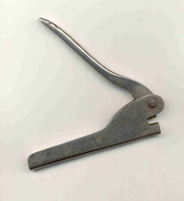 Ballarat Tramway Museum
Functional Object - Sealing Punch, 1912?
... Nickel plated steel sealing punch - with base unit, spring, handles, pins and punch or press that was used to seal or secure lead seals either on power meters, ticket boxes or circuit breakers. Placed letters "M.E.S. ...Trams tramways Sealing MESCo Seals Nickel plated steel sealing punch - with base unit, spring, handles, pins and punch or press that was used to seal or secure lead seals either on power meters, ticket boxes or circuit breakers. Placed letters "M.E.S. ...Has a strong association with the Geelong tramway system, yields information about the sealing or securing equipment from interference and demonstrates the type of equipment used. Exact use not known - could have been used for multiple purposes.Nickel plated steel sealing punch - with base unit, spring, handles, pins and punch or press that was used to seal or secure lead seals either on power meters, ticket boxes or circuit breakers. Placed letters "M.E.S. Co Ltd" onto the lead seal along with numbers "1". On outside of handle "PAT. 9682 1902" and in inside ".1" - the number of the press? Knowledge of manufacturer unknown - possibly the UK. Could research the Patent numbers - a quick search at the time failed to show something.trams, tramways, sealing, mesco, seals -
 Ballarat Tramway Museum
Equipment - Equipment - Controller, Tram Controller, Possible from Tram 22
... The controller is supplied with power via a current limiting automatic circuit breaker. It has a handle on top and this turns a drum fitted with insulated copper segments. ...The controller is supplied with power via a current limiting automatic circuit breaker. It has a handle on top and this turns a drum fitted with insulated copper segments. ...Controller from an old tram, possible Tram 22. Appears to be a typical parallel drum controller with the casing removed. The arc shield is in place. With this swung back the drum segments and fingers are revealed. The controller is supplied with power via a current limiting automatic circuit breaker. It has a handle on top and this turns a drum fitted with insulated copper segments. There is usually a star wheel and roller which ensures that the drum advances in notches to match the drum segments.Large laminated photograph of a tram controller c1920controller, tramcars, parallel drum controller, automatic circuit breaker, handle, star wheel -
 Melbourne Tram Museum
Album - Photographs - Comeng Dandenong, 1980s - 1990s
... Oct 1992 (based on delivery date) Comeng Scans 2024-03-05 0065 Victorian Premier Joan Kirner addresses a group of dignitaries in front of an ABB banner inside the main administration building at Dandenong, on the occasion of the first XPT power car purchased by Victoria being unveiled at a media event c. 1992 Comeng Scans 2024-03-05 0066 An ABB executive addresses a group of dignitaries in front of an ABB banner inside the main administration building at Dandenong, on the occasion of the first XPT power car purchased by Victoria being unveiled at a media event c. 1992 Comeng Scans 2024-03-05 0067 Victorian Premier Joan Kirner addresses the media in front of a completed XP class XPT power car at Dandenong, on the occasion of the first XPT power car purchased by Victoria being unveiled at a media event c. 1992 Comeng Scans 2024-03-05 0068 An exterior shot of a new Countrylink XP power car at Comeng Dandenong c. 1992 Comeng Scans 2024-03-05 0069 A Melbourne B2 class tram undergoing testing on the test circuit at ABB Dandenong c. early 1990s Comeng Scans 2024-03-05 0070 An XPlorer type DMU emerges from a shed at ABB Dandenong c.1994 Comeng Scans 2024-03-05 0071 Voith final drive axle mounted units for XPlorer railcars waiting to be fitted at Dandenong. ...Oct 1992 (based on delivery date) Comeng Scans 2024-03-05 0065 Victorian Premier Joan Kirner addresses a group of dignitaries in front of an ABB banner inside the main administration building at Dandenong, on the occasion of the first XPT power car purchased by Victoria being unveiled at a media event c. 1992 Comeng Scans 2024-03-05 0066 An ABB executive addresses a group of dignitaries in front of an ABB banner inside the main administration building at Dandenong, on the occasion of the first XPT power car purchased by Victoria being unveiled at a media event c. 1992 Comeng Scans 2024-03-05 0067 Victorian Premier Joan Kirner addresses the media in front of a completed XP class XPT power car at Dandenong, on the occasion of the first XPT power car purchased by Victoria being unveiled at a media event c. 1992 Comeng Scans 2024-03-05 0068 An exterior shot of a new Countrylink XP power car at Comeng Dandenong c. 1992 Comeng Scans 2024-03-05 0069 A Melbourne B2 class tram undergoing testing on the test circuit at ABB Dandenong c. early 1990s Comeng Scans 2024-03-05 0070 An XPlorer type DMU emerges from a shed at ABB Dandenong c.1994 Comeng Scans 2024-03-05 0071 Voith final drive axle mounted units for XPlorer railcars waiting to be fitted at Dandenong. ...In March 2024, Milissa Box (DTP) was at a trash and treasure market. She'd found a $5 photo album for sale with some photos that she thought might be of interest… From what I can gather it belonged to the gentleman pictured who was a worker at Dandenong in the Comeng and ABB eras. He appears to have worked on the Z3, A1/A2, B1/B2 class trams, Hong Kong LRVs, Comeng Melbourne suburban trains, and later the extra Victorian-purchased XP power cars and XAM sleepers to enable the Riverina XPT to be extended to Melbourne. It's clear he was very proud of the vehicles he'd helped to build. I have scanned a selection of the images, which appear to be a mix of official builder's portraits, team photos, and self-taken shots showing candid everyday scenes on the shop floor. There are also images of the launch of the XP power cars with then-Victorian Premier Joan Kirner; and some personal visits to see the Flying Scotsman, Victorian Goldfields Railway, Coal Creek, etc. Filename Description Date Comeng Scans 2024-03-05 0001 Three Comeng workers (including the photographer) stand in front of Comeng suburban train 697M (Chopper unit) c. June-July 1989 Comeng Scans 2024-03-05 0002 Three Comeng workers (including the photographer) stand in front of Comeng suburban train 697M (Chopper unit) c. June-July 1989 Comeng Scans 2024-03-05 0003 Hong Kong Light Rail Phase 1 LRV 1013 being lifted onto its transport loader c. 1987-88 Comeng Scans 2024-03-05 0004 Walter Wright transport truck (Mack) waits to draw a heavy transport platform out of a shed at Comeng Dandenong. Hong Kong Phase I LRV (1024) can be seen inside the shed c. 1988 Comeng Scans 2024-03-05 0005 Hong Kong Light Rail Phase 1 LRV 1013 on its transport loader in a shed at Comeng Dandenong ready for transport c. 1988 Comeng Scans 2024-03-05 0006 Hong Kong Light Rail Phase 1 LRV 1013 on its transport loader in a shed at Comeng Dandenong ready for transport c. 1988 Comeng Scans 2024-03-05 0007 The photographer is pictured fitting components to the cab of a Phase I Hong Kong LRV No 1026 c. 1988 Comeng Scans 2024-03-05 0008 Hong Kong Light Rail Phase 1 LRV 1013 on its transport loader at Comeng Dandenong ready for transport c. 1988 Comeng Scans 2024-03-05 0009 Hong Kong Light Rail Phase 1 LRV 1013 on its transport loader at Comeng Dandenong ready for transport c. 1988 Comeng Scans 2024-03-05 0010 Hong Kong Light Rail Phase 1 LRV 1013 on its transport loader at Comeng Dandenong ready for transport c. 1988 Comeng Scans 2024-03-05 0011 The photographer and a colleague are pictured in the car park posing for a photo at Comeng Dandenong c. 1988 Comeng Scans 2024-03-05 0012 The photographer and a colleague are pictured inside the cab of Comeng suburban train 697M, posing for a photo at Comeng Dandenong c. 1989 Comeng Scans 2024-03-05 0013 A stainless steel Hitachi train bodyshell is being transported on a truck-trailer. Possibly taken at Martin and King in Bayswater, under transport to the station for railing to Somerton for fitout. This is a later series M car with the rear-mounted pantograph (note the mounting lugs above the non-driving end) c. 1980 Comeng Scans 2024-03-05 0014 A shot at Comeng Dandenong of the onsite workforce standing in front of a Phase I Hong Kong LRV. c.1987-88 Comeng Scans 2024-03-05 0015 A shot at Comeng Dandenong of the onsite workforce standing in front of a Phase I Hong Kong LRV. c.1987-88 Comeng Scans 2024-03-05 0016 Hong Kong Light Rail Phase 1 LRV 1038 on its transport loader at Port of Melbourne ready for transport c. 1988 Comeng Scans 2024-03-05 0017 Three Comeng workers (including the photographer) stand in front of a workbench at Comeng Dandenong c. June-July 1989 Comeng Scans 2024-03-05 0018 A newly completed Comeng train (wearing VicRail teacup orange) on the factory access track at Comeng Dandenong c. 1981 Comeng Scans 2024-03-05 0019 A newly completed Z3 class tram on a transporter, with its bogie frames waiting transport to Preston Workshops for final fitout and commissioning c. 1981 Comeng Scans 2024-03-05 0020 A newly completed Comeng train (wearing VicRail teacup orange) on the factory access track at Comeng Dandenong c. 1981 Comeng Scans 2024-03-05 0021 A newly completed Z3 class tram on a transporter, with its bogie frames waiting transport to Preston Workshops for final fitout and commissioning c. 1981 Comeng Scans 2024-03-05 0022 A Comeng/ABB artist impression presumably part of their bid for the Double Decker demonstrator train for Melbourne. Note the similarity to similar Comeng sets constructed for Sydney. c. Nov 1989 – April 1990 Comeng Scans 2024-03-05 0023 Victorian Railways steam locomotive K 169 on static display at Coal Creek. c. 1980s Comeng Scans 2024-03-05 0024 Comeng suburban train carriage 1190T on a traverser in the yard at Comeng Dandenong. c. June-July 1989 Comeng Scans 2024-03-05 0025 Comeng suburban train carriages the yard at Comeng Dandenong. c. June-July 1989 Comeng Scans 2024-03-05 0026 Comeng suburban train carriages the yard at Comeng Dandenong. c. June-July 1989 Comeng Scans 2024-03-05 0027 Comeng suburban train carriages the yard at Comeng Dandenong. c. June-July 1989 Comeng Scans 2024-03-05 0028 Comeng suburban train carriages the yard at Comeng Dandenong. c. June-July 1989 Comeng Scans 2024-03-05 0029 Comeng suburban train in a shed at Comeng Dandenong. c. June-July 1989 Comeng Scans 2024-03-05 0030 Comeng suburban train carriage 1190T on a traverser in the yard at Comeng Dandenong – possible Factory Acceptance Inspection by the Met c. June-July 1989 Comeng Scans 2024-03-05 0031 Comeng suburban train carriage 1190T being tractor-shunted in the yard at Comeng Dandenong – possible Factory Acceptance Inspection by the Met c. June-July 1989 Comeng Scans 2024-03-05 0032 Two Comeng workers carry a train part (possibly a first aid kit) for fitting to a Comeng suburban train. c. June-July 1989 Comeng Scans 2024-03-05 0033 Comeng suburban train carriage 1190T on a traverser in the yard at Comeng Dandenong – possible Factory Acceptance Inspection by the Met. One of the Met staff appears to be giving one of the Comeng workers a kiss on the cheek. c. June-July 1989 Comeng Scans 2024-03-05 0034 A B2 Class tram is on a low-loader multiwheel transport trailer waiting transport to Preston Workshops; while what appears to be a classic AP6 Valiant Safari Wagon is in the foreground. c. June-July 1989 Comeng Scans 2024-03-05 0035 A B2 Class tram is on a low-loader multiwheel transport trailer waiting transport to Preston Workshops; while a worker poses for a photo with his hand on the rigging. c. June-July 1989 Comeng Scans 2024-03-05 0036 A B2 Class tram is on a low-loader multiwheel transport trailer waiting transport to Preston Workshops; An HT Holden Belmont sedan has been posed in front to appear as if it is towing the heavy vehicle. c. June-July 1989 Comeng Scans 2024-03-05 0037 A B2 Class tram is on a low-loader multiwheel transport trailer waiting transport to Preston Workshops; An HT Holden Belmont sedan has been posed in front to appear as if it is towing the heavy vehicle. c. June-July 1989 Comeng Scans 2024-03-05 0038 A1 Class tram 232 is pictured up on stands while various A/B class tram cab frames are in the foreground in various stages of assembly. Of note, 232 appears to have been returned to Dandenong for major repair or other work, and shows signs of having been in traffic for some time (weathering and wear) c. June-July 1989 Comeng Scans 2024-03-05 0039 various A/B class tram cab frames are in the foreground in various stages of assembly. c. June-July 1989 Comeng Scans 2024-03-05 0040 A group of Comeng Dandenong workers stopped on a tea break. c. June-July 1989 Comeng Scans 2024-03-05 0041 An A/B Class tram cab being fitted out with electronics and controls. c. June-July 1989 Comeng Scans 2024-03-05 0042 A new Comeng suburban train in Metropolitan Transit livery on the test track at Comeng Dandenong. c. mid 1980s Comeng Scans 2024-03-05 0043 A new Comeng suburban train in Metropolitan Transit livery on the test track at Comeng Dandenong. c. mid 1980s Comeng Scans 2024-03-05 0044 Interior shot of a new Comeng suburban train at Comeng Dandenong. c. mid 1980s Comeng Scans 2024-03-05 0045 Interior shot of a new Comeng suburban train at Comeng Dandenong. c. mid 1980s Comeng Scans 2024-03-05 0046 The exterior sign at Dandenong showing ABB brand. Early 1990s Comeng Scans 2024-03-05 0047 A B2 Class tram is on a low-loader multiwheel transport trailer waiting transport to Preston Workshops. Early 1990s Comeng Scans 2024-03-05 0048 The Brush generator and Paxman Valenta engine as fitted inside a new XP power car for NSW Countrylink (paid for by Victoria) c. 1992 Comeng Scans 2024-03-05 0049 An exterior shot of a new Countrylink XP power car for NSW under construction (paid for by Victoria) c. 1992 Comeng Scans 2024-03-05 0050 Two new XAM class XPT sleeper carriages under construction at Comeng Dandenong c. 1992 Comeng Scans 2024-03-05 0051 A B2 class tram under construction at Comeng Dandenong Early 1990s Comeng Scans 2024-03-05 0052 A B2 class tram under construction at Comeng Dandenong Early 1990s Comeng Scans 2024-03-05 0053 An exterior shot of a new Countrylink XP power car for NSW being moved out of the shed c. 1992 Comeng Scans 2024-03-05 0054 An exterior shot of a new Countrylink XP power car at Comeng Dandenong c. 1992 Comeng Scans 2024-03-05 0055 An exterior shot of a new Countrylink XP power car at Comeng Dandenong c. 1992 Comeng Scans 2024-03-05 0056 An exterior shot of a new Countrylink XP power car at Comeng Dandenong c. 1992 Comeng Scans 2024-03-05 0057 B2 class trams under construction at Comeng Dandenong Early 1990s Comeng Scans 2024-03-05 0058 An XP Powercar from NSW wearing the Intercity XPT Candy Livery at Comeng Dandenong. It is not known if this was originally painted in this livery (incorrectly) or if this was one of the first delivered series transported to Dandenong to aid the construction process of the four additional locomotives. Early 1990s Comeng Scans 2024-03-05 0059 Melbourne B2 Class tram B2.2100 (renumbered from 2102) painted in the distinctive Chocolate and Cream livery to mark the completion of 100 B2 class trams Early 1990s Comeng Scans 2024-03-05 0060 A factory forklift wearing a hand painted “We love Labo(u)r” cardboard sign, possibly in connection to a media event with the Victorian Premier onsite at Comeng Dandenong. c. 1992 Comeng Scans 2024-03-05 0061 An exterior shot of a new Countrylink XP power car at Comeng Dandenong c. 1992 Comeng Scans 2024-03-05 0062 Two new new Countrylink XP power cars under construction and final fitout at Comeng Dandenong c. 1992 Comeng Scans 2024-03-05 0063 An exterior shot of a new Countrylink XP power car on the traverser at Comeng Dandenong c. 1992 Comeng Scans 2024-03-05 0064 A B2 Class tram is on a low-loader multiwheel transport trailer waiting transport to Preston Workshops. A large banner is draped on the side explaining that this is the 106th vehicle delivered to the Public Transport Corporation (B2.2108). c. Oct 1992 (based on delivery date) Comeng Scans 2024-03-05 0065 Victorian Premier Joan Kirner addresses a group of dignitaries in front of an ABB banner inside the main administration building at Dandenong, on the occasion of the first XPT power car purchased by Victoria being unveiled at a media event c. 1992 Comeng Scans 2024-03-05 0066 An ABB executive addresses a group of dignitaries in front of an ABB banner inside the main administration building at Dandenong, on the occasion of the first XPT power car purchased by Victoria being unveiled at a media event c. 1992 Comeng Scans 2024-03-05 0067 Victorian Premier Joan Kirner addresses the media in front of a completed XP class XPT power car at Dandenong, on the occasion of the first XPT power car purchased by Victoria being unveiled at a media event c. 1992 Comeng Scans 2024-03-05 0068 An exterior shot of a new Countrylink XP power car at Comeng Dandenong c. 1992 Comeng Scans 2024-03-05 0069 A Melbourne B2 class tram undergoing testing on the test circuit at ABB Dandenong c. early 1990s Comeng Scans 2024-03-05 0070 An XPlorer type DMU emerges from a shed at ABB Dandenong c.1994 Comeng Scans 2024-03-05 0071 Voith final drive axle mounted units for XPlorer railcars waiting to be fitted at Dandenong. c.1994 Comeng Scans 2024-03-05 0072 A completed XAM class sleeper carriage at ABB Dandenong. c.1993 Comeng Scans 2024-03-05 0073 Completed XPlorer railcars wait transfer to South Dynon for bogie exchange and transfer to NSW at ABB Dandenong. c. 1994 Comeng Scans 2024-03-05 0074 A clipping from an ABB internal newsletter outlining the staff-led initiative to commemorate the 100th B2 class tram with a special livery c.1992 Has photographs of ABB, Steamrail tours, Castlemaine and Maldon Railway, Fying Scotsman 4472 visit and Puffing Billy.Yields information about the people and events at Commonwealth Engineering plant Dandenong and the activities of the unknown compiler.Album containing 40 leaves, photos in a heavy card 3 ring spring binder.comeng, commonwealth engineering co., tramcars, hong kong, nsw, sydney, melbourne, railways, the met, b class, cmr, steam engines, abb, asea brown boveri -
 Anglesea and District Historical Society
Radio, AWA (Amalgamated Wireless (Australasia) Ltd), AWA Radiolette 500MY, 1946-47
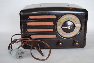
... Tuned circuits: 6AM Wavebands: Broadcast only (MW) Power: 200-230; 230-260 Volt AC. ...Tuned circuits: 6AM Wavebands: Broadcast only (MW) Power: 200-230; 230-260 Volt AC. ...Australian bakelite valve tube radio. Type: Broadcast receiver or past WW2 Tuner. Valves 4:6A8G 6G8g 6V6GT 6x5GT. Principle: Super Heterodyne ZF/IF 455 KHz 1AF stage. Tuned circuits: 6AM Wavebands: Broadcast only (MW) Power: 200-230; 230-260 Volt AC. Loudspeaker: Electro Magnetic Dynamic LS Front Dial: AWA Radiolette / Radio stations for each stateradio, radiolette -
Ballarat Tramway Museum
Document - Folder with papers, Garry Wood and Paul Mong, "Ballarat Tramway Museum / Electrical Diagrams for Sub Station / 12-11-2005", Nov. 2005
... Ballarat Tramway Museum South Gardens Reserve Wendouree Parade Ballarat Ballarat goldfields Trams tramways Substation BTM Power Supply Blue Victory plastic folder with clear front cover, containing 15 plastic sheet protectors and printed or photocopied sheets detailing the equipment in the rebuilt BTM Sub-station. Titled "Ballarat Tramway Museum / Electrical Diagrams for Sub Station / 12-11-2005", details control circuit ...Blue Victory plastic folder with clear front cover, containing 15 plastic sheet protectors and printed or photocopied sheets detailing the equipment in the rebuilt BTM Sub-station. Titled "Ballarat Tramway Museum / Electrical Diagrams for Sub Station / 12-11-2005", details control circuit, Traction Encloser, Cabinet C1, Cabinet C2, Cabinet C/C3, photographs, parts list, Micro electrics, Traction Contactors, Type LTHS, K&J Magnetics, NHP under or over current single phase relays, and Carlo Cavazzi Monitoring Relays.trams, tramways, substation, btm, power supply -
 Uniting Church Archives - Synod of Victoria
Badge - Symbol of Office
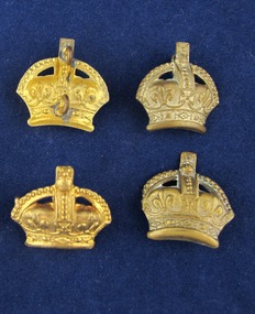
... The aims of the MGC was to "challenge young people with the saving power of Jesus Christ and provide avenues of Christian service" and "to provide for the spiritual, social, physical and educational welfare of the members". The MGC's motto was "The Utmost for the Highest". The Director was appointed by the Leaders' Meeting on the nomination of the Superintendent Minister of the Circuit...The aims of the MGC was to "challenge young people with the saving power of Jesus Christ and provide avenues of Christian service" and "to provide for the spiritual, social, physical and educational welfare of the members". The MGC's motto was "The Utmost for the Highest". The Director was appointed by the Leaders' Meeting on the nomination of the Superintendent Minister of the Circuit ...The Methodist Girls' Comradeship was formed in 1918 with the first Branch being in Bondi, NSW. There were three sections: Junior Rays, 8 - 11 years; Senior Rays, 11 - 15 years and Comrades, 15 years and over. The aims of the MGC was to "challenge young people with the saving power of Jesus Christ and provide avenues of Christian service" and "to provide for the spiritual, social, physical and educational welfare of the members". The MGC's motto was "The Utmost for the Highest". The Director was appointed by the Leaders' Meeting on the nomination of the Superintendent Minister of the Circuit. It was desirable that she was a member of the Third Degree.Four metallic gold crowns; Director symbols.methodist girls' comradeship, director badge -
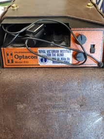 Vision Australia
Equipment - Object, Telesensory Systems, Optacon, 1974
... Powered by a rechargeable battery, and comes with its own battery charger. The battery is contained within the main chassis, and is not removable by the user. There are four basic controls on the Optacon: the Magnification Adjustment zoom button located on the camera section on the side opposite the rollers; and the On-Off switch, the Stimulator Intensity Adjustment knob, and the Threshold Adjustment knob located on the right side of the front panel. The Circuit...Powered by a rechargeable battery, and comes with its own battery charger. The battery is contained within the main chassis, and is not removable by the user. There are four basic controls on the Optacon: the Magnification Adjustment zoom button located on the camera section on the side opposite the rollers; and the On-Off switch, the Stimulator Intensity Adjustment knob, and the Threshold Adjustment knob located on the right side of the front panel. The Circuit ...The Optacon OPtical-to-TActile-CONverter is a compact, portable reading aid for the blind. It is about the size of a textbook, and weighs less than 2kg. It works by converting a printed image into a tactile image that a blind person can feel with one finger. After a period of training and practice, a blind person can use the Optacon to read ordinary books, magazines, newspapers, and other printed materials. The Optacon was developed after intensive research at Standford University, California, USA and was trialed by clients of the Royal Victorian Institute for the Blind (now part of Vision Australia) in 1973. It has three main sections: 1 a miniature camera, 2 an electronics section, and 3 a tactile stimulator array. The miniature camera, about the size of a pocket knife, is mounted in a housing that has rollers for easy movement along a line of print. The camera is connected to the electronics section by a lightweight cable. The electronics section and the tactile stimulator array are in the main chassis. The array consists of 144 tiny metal rods arranged in six vertical columns and 24 horizontal rows. Each of the rods can vibrate independently. The tips of these rods protrude through holes in a concave finger plate where the index finger is placed flat in order to read. These three components act together to convert the image of a printed letter or other shape into a pattern of vibrating rods, a tactile image of the letter or shape. The letter shape is tactually perceived as an image that moves from right to left on the finger, showing the left or leading edge of the letter first. Letters are felt sequentially rather than all at once, and the image should be kept moving. The Optacon converts a printed O into a tactile form that resembles a crater with a vibrating rim -- a completed circle. C would have a gap or opening on the right side of the curve. The letter F would be felt, sequentially, as a vertical line with two trailing horizontal lines. Because it can convert any ordinary printed image into a corresponding tactile image, the Optacon is not restricted to any special typestyle or language. The camera has a zoom lens that compensates for differences in the size of type. The standard Optacon lens can accommodate type sizes from 6 point to 20 point. With the optional F4A magnifier lens, type sizes as small as 4 point can be read. Powered by a rechargeable battery, and comes with its own battery charger. The battery is contained within the main chassis, and is not removable by the user. There are four basic controls on the Optacon: the Magnification Adjustment zoom button located on the camera section on the side opposite the rollers; and the On-Off switch, the Stimulator Intensity Adjustment knob, and the Threshold Adjustment knob located on the right side of the front panel. The Circuit Breaker protrudes from the right-hand wall inside the chassis compartment. From left to right when the back panel is facing you, are located: the jack for connecting the battery charger; the Battery Check button; the Normal-Invert switch; and the Input/Output I/O connector for use with the Visual Display, when using the Repeater Cable to connect two Optacons to one another or with other accessories. Designed not be removed from the leather case during normal operation, the On-Off switch is a slide switch located on the right side of the front panel. It slides up and snaps into place in the on position. 1 black with orange front, rectangular device in leather case assistive devices, audio equipment -
 Whitehorse Historical Society Inc.
Equipment - Magneto Telephone, C1930
... The hook acts as the on and off switch to answer the call and to switch on the battery to provide power for the receiver and energize the transmitter. There is an angled ledge for writing any messages. There is no battery. The circuit...The hook acts as the on and off switch to answer the call and to switch on the battery to provide power for the receiver and energize the transmitter. There is an angled ledge for writing any messages. There is no battery. The circuit ...Used to communicate with the local telephone exchange and for connection to other subscribers. The introduction of automatic exchanges saw the their demise. This phone was used in the family home of the donor at Caboolture (aboriginal for carpet snake) during the 1940s and 1950s.A magneto telephone for communication with a manual telephone exchange. The handle on the right hand side, which was turned to rotate the magneto to call the exchange - ask operator for a number and then to be connected. Telephone enclosed in a specially designed box for mounting on the wall. There was a bell on top which rang when the magneto ringer at the exchange was turned. Fitted with a carbon microphone mounted on the front of the box for the transmission of the spoken word and an electro- magnet. A receiver which hangs on the left hand side on a hook. The hook acts as the on and off switch to answer the call and to switch on the battery to provide power for the receiver and energize the transmitter. There is an angled ledge for writing any messages. There is no battery. The circuit for the phone is on the inside of the door to the interior of the phone. pHone is type CDA116 - PMG Registered - Ericsson.communication, telephonic -
Moorabbin Air Museum
Manual - Ansett Douglas DC9 technical manuals, DC - 9 Airframe Course Notes
... power...Equipment/furnishings...Fire protection...Flight controls...Fuel...Hydraulics...Ice & rain protection...Instrument & circuit...Ansett Douglas DC9 technical manuals Maintenance checks Dimensions & areas Lifting Levelling Towing & taxiing Parking Standard airplane practices Air conditioning AFCS/Auto throttle Electrical power Equipment/furnishings Fire protection Flight controls Fuel Hydraulics Ice & rain protection Instrument & circuit breaker panels Landing gear Lights Navigation instruments Oxygen Pneumatics Water & waste systems APU General structures Doors & airstairs Technical course notes for Douglas DC-9, circa 1966 2 clip binder DC - 9 Airframe Course Notes Manual Ansett Douglas DC9 technical manuals ...Technical course notes for Douglas DC-9, circa 19662 clip bindernon-fictionTechnical course notes for Douglas DC-9, circa 1966maintenance checks, dimensions & areas, lifting, levelling, towing & taxiing, parking, standard airplane practices, air conditioning, afcs/auto throttle, electrical power, equipment/furnishings, fire protection, flight controls, fuel, hydraulics, ice & rain protection, instrument & circuit breaker panels, landing gear, lights, navigation instruments, oxygen, pneumatics, water & waste systems, apu, general structures, doors & airstairs