Showing 52 items
matching concrete dam
-
 Kiewa Valley Historical Society
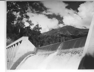
Photograph of Lake Guy Dam, Spillway, Lake Guy Dam, c1945
In December 1939 the excavation of the diversion tunnel at the site of Junction (Lake Guy) Dam was commenced and finished in February, 1940.This allowed the stream to be diverted to facilitate the dam wall construction. This is a 'slab and buttress' dam. It is framed with timber and concrete then poured into the structure. A contract was let to Lewis Construction Co. for the construction of the dam, and the first batch of concrete was placed in September, 1940. Industrial trouble caused some delays but there was also slow progress on the part of the contractor and the work was taken over by the S.E.C., terminating the contract. The dam was completed in March, 1944. The lake is named after Mr. L.T. Guy who was the Resident Engineer, in charge of construction work and associated activities on the Kiewa area, from 1939 until November 1946. An historical pictorial record taken for the State Electricity Commission of Junction Dam (Lake Guy) on spill. Mt. Arthur is in the background and there is still evidence of the destruction of trees from the 1939 bushfires. Black and white photograph of Lake Guy Dam . The dam is spilling and Mt. Arthur is in the background. Hand written on back of photograph in blue ink " Lake Guy Dam".dam, lake, water, mr. l.t.guy -
 Kiewa Valley Historical Society
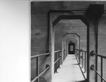
Photograph of Lake Guy Dam, Walkway, Inside Lake Guy Dam, c 1945
Lake Guy Dam is a 'slab and buttress' type wall. A timber frame is built and then filled with concrete. The first batch of concrete was placed in September, 1940. By June, 1941 the buttresses were finished to a height safe from floods and in October of that year a flood of 2,800 cusecs occurred but with only slight damage to the installations. Industrial trouble caused some delays but there was also slow progress on the part of the contractor and the work was taken over by the S.E.C., terminating the contract. The dam was completed in March, 1944. A walkway was made through the dam wall. Lake Guy was named after Mr. L.T. Guy who was the Resident engineer, in charge of construction work and associated activities on the Kiewa Area from 1939 to November 1946.Shows the walkway placed as part of the Lake Guy (Junction) Dam wall. A very good pictorial reference for the future.Black and white photograph of the walkway through Lake Guy (Junction) Dam wall.Handwritten in blue ink on back of photograph "Inside Lake Guy Dam". slab, buttress, dam, mr. l.t. guy -
 Kiewa Valley Historical Society
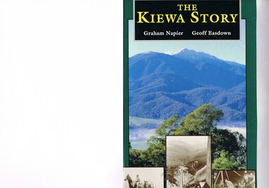
Book - Non Fiction History, The Kiewa Story, circa 1993
This book provides in chronological order the development of the Kiewa Hydro-electricity scheme from the first concept (1911) to final construction work (1961). It covers the first attempt to utilise the power of the Victorian Alps water system. It started from a private syndicate and developed to the current State Electricity Commission of Victoria. The incentive for the Hydro scheme was to make money and not as an alternative to the carbon producing coal fired power plants. These coal fired power plants were increasing in numbers to service an ever increasing demand made by population expansion, especially in cities and large rural settlements. This demand spiraled up after World War II when there was a tremendous spike in immigration numbers due to refugees and displaced persons in Europe. The ability to utilise the untapped water provided by the winter snow fields, for a higher yield in electricity, was a powerful incentive to overcome the physical hardships in this remote Alpine region. Future power requirements may initiate the re-installation of the other two power stations(Pretty Valley and Big Hill) covered in original Scheme. This publication not only covers the development of the Kiewa Valley region with respect to population (within a socio-economical framework) but also the subtle but yet strong physical changes of a relatively pristine alpine region. The demands that an ever growing regional population places on the environment is clearly documented in print and black and white photographs. The working and living conditions of those who constructed and gave life to this hydro scheme is well documented in this book. It may be viewed as spartan now but was relevantly good at that moment in time, especially for those workers fleeing a devastated European environment. The successful planning and consideration to minimising any intrusion upon the natural alpine forests and high plains can viewed as an example (compared to the Tasmanian Hydro schemes) of how future hydro schemes (an inevitable requirement) will proceed. Most rural towns (in the early 1900s) were built by unencumbered rural based citizens, with the exception of Mount Beauty and Falls Creek. These two settlements were brought into life by a State (Victorian) Authority for a specific function and program. They were a gated community, that is, only open to construction workers involved with the hydro scheme. All facilities within these communities were provided by the State Electricity Commission of Victoria. The impact on the social, financial and individual independency of the community, by the transition from the S.E.C .environment to one of local government (Shire of Bright), had in some cases a severe impact.This hard covered book has a green cover with pictures on the front and back covers. The front cover has a coloured picture of a snow covered Mount Bogong taken from the opposite mountain range. The valley between both ranges has a whisk of mist over it. At the bottom of this picture are three black and white photographs covering the construction of the Kiewa Hydro - Electricity Scheme. On the back cover is a photograph, (black and white) detailing the Bogong village and Junction dam containing lake Guy. The inside front cover is a black and white photograph which details the construction of the West Kiewa tailrace tunnel during April 1951. The inside back cover is a black and white photograph of the concrete pour at the Clover Dam circa 1952. All photographs and sketches are in black and white. The pages are approximately 160 g/m2 and those which have photographs are on gloss paper.Book spine: "The Kiewa Story Graham Napier Geoff Easdown" alongside this is a white framed circle with white spokes radiating out and underneath in white lettering SECkiewa valley, hydro scheme, victorian alpine region, electricity generators, graham napier, geoff easdown -
 Eltham District Historical Society Inc
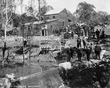
Negative - Photograph, Opening of St. Andrews Battery, Queenstown, 29 Aug. 1919
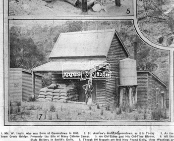
Reproduced on p31 of 'Pioneers & Painters' Was destroyed in 1962 bushfire. Now Peter Franks Reserve, St Andrews On Friday 29th (August 1919) …, the Hon. S. Barnes, M. L. A., Minister of Mines, accompanied by Mr W. Everard, M.L.A., Mr. V. Dickson, secretary for Mines, and Mr. Merrin, Chief Mining Inspector, visited Smith's Gully for the purpose of opening, the new Government battery which has recently been erected. The party arrived punctually at 12.30, and was received by an assemblage of about 200 residents, including, those representing local prospecting and mining interests. At the mill house the Minister wished prosperity to mining on the old Queenstown field, and, in a few appropriate remarks, gave the battery the name of St. Andrew's. Then, as the stamps began to fall, three hearty cheers were given by the gathering. ….. The Queenstown field, dating back to the early sixties, might be regarded as a link that took them back to the Augustine age of gold mining in Victoria…From 1868 to 1918 the total yield of gold from the field was 274,606 fine oz. It might be that here, as elsewhere, deeper prospecting would give new life to the Queenstown goldfield. The miners of Queenstown, who through long year's had never lost faith in the possibilities of the field, felt that the purpose for which they were that day marked the beginning of a new era in the history of local reefing. …. The new mill is situated on the bank of the creek opposite the Queenstown Cemetery, and consists of a five head battery (Berdan pan) and 12 h.p. portable steam engine housed in a spacious structure of wood and iron. A concrete weir across the creek provides a good water supply, and all the necessary pumps, settling dams, etc., have been installed. Later on, should circumstances warrant it, it is pro-posed to erect Wilfley tables for concentrates. Eltham and Whittlesea Shires Advertiser and Diamond Creek Valley Advocate, Friday 5 September 1919, page 3This photo forms part of a collection of photographs gathered by the Shire of Eltham for their centenary project book,"Pioneers and Painters: 100 years of the Shire of Eltham" by Alan Marshall (1971). The collection of over 500 images is held in partnership between Eltham District Historical Society and Yarra Plenty Regional Library (Eltham Library) and is now formally known as the 'The Shire of Eltham Pioneers Photograph Collection.' It is significant in being the first community sourced collection representing the places and people of the Shire's first one hundred years.Digital image 4 x 5 inch B&W Neg Print 20 x 25 (2)shire of eltham pioneers photograph collection, queenstown, st andrews, st. andrews battery, gold mining, s. barnes, merrin, st andrews battery, v. dickson, william h. everard, peter franks reserve -
 Bendigo Historical Society Inc.
Document - CENTRAL NELL GWYNNE GOLD MINE
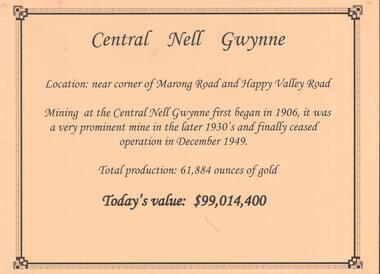
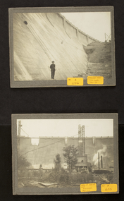
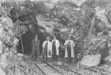
Interpretive sign and 4 photos Central Nell Gwynne Gold Mine, used in display. Central Nell Gwynne was located near the corner of Marong Road and Happy Valley Road. Opened in 1906, ceased operation in December 1949. Total production: 61,884 ounces of Gold. Today's Value: $99,014,400. Photos: a. Colour photo, concrete footings at mine site, April 2012. b. Colour photo, Central Nell Gwynne poppet head, April 2012.Poppet head painted white with red trim. Concrete footings in foreround. c. Central Nell Gwynne mine site 1930's. Poppet head and engine room sheds on LH side, trestle way to primary crusher and crushing battery. Tailing dam in immediate foreground. on RH side. Sand heaps in middle foreground. d. Central Nell Gwynne Mine 1930. Underground view, men holding carbide lamps working at 265 level in mine. Large quartz spur formation visible in foreground.bendigo, mining, central nell gwynne -
 Melbourne Water
Photographs: The Maroondah Dam Wall Under Construction, 1921-1922
The Maroondah System was first and foremost developed as a functional component of Melbourne's Water Supply System. In addition to functionality, the Melbourne and Metropolitan Board of Works (MMBW) envisioned the Maroondah Reserve to be enjoyed aesthetically and recreationally by the public. This souvenir illustrates the realisation of the Maroondah System as a local recreational and tourist attraction in the early 20th century. The Maroondah Reserve gardens were landscaped with English-style ornamental stonework, exotic trees, flower beds and rose gardens. All features of the water supply system became widely celebrated as beauty spots that continue to be very popular to this day with tourists and locals alike. This souvenir is a product of that flourishing tourist trade. These water supply sites continue to enhance Melbourne’s charm and liveability and are now recognised as places of cultural and historic significanceThese photographs are invaluable in providing insight into many aspects of the Maroondah Reservoir’s early development. The dam wall is a distinctive example of early engineering techniques, with its gravity arch design and concrete construction. The construction of the dam wall represents an important advancement in the technology of dam-building.These images are part of a series of eight photographs which document the construction of the Maroondah Dam in the 1920s.melbourne metropolitan board of works, mmbw, melbourne water, photograph, water, maroondah dam, construction, wall -
 Melbourne Water
Photograph - Tunnel at the O'Shannasy Dam, 9th April 1921
The O'Shannassy Reservoir supplies water to the Silvan Reservoir, which distributes it to most parts of Melbourne. The dam was completed in 1928 and is an earthfill embankment with a reinforced concrete core wall.This photograph is significant as it provides a detailed insight into the Boards activity and construction of one of Melbourne's most important water supply systems. Furthermore, it is of historical importance to the history of Melbourne while it is representative of shaping Melbourne's environments, transforming and managing land and natural resources, and providing urban infrastructure and services. This photograph also covers the theme of Safety, depicting the safety standards of the time particularly with clothing. Black and white photographmmbw, melbourne metropolitan board of works, melbourne water, silvan reservoir, o'shannassy reservoir, construction, work, men, infrastructure -
 Tatura Irrigation & Wartime Camps Museum
Photograph, 1917
Taken by photographer for State Rivers and Water Supply Commission.Medium sized black and white photograph. 30/6/1917 Sugarloaf Dam wall construction / Timber form-work ready for concrete pour / Four workmen in foreground / Engine track rail line left / Hut at foot of hill loomingvictorian state rivers and supply commission, sugarloaf dam -
Tatura Irrigation & Wartime Camps Museum
Photograph, Eildon Reservoir - Goulburn River, 1918
... acre feet / Rock filled dam with mass concrete spillway / Total... - 306,000 acre feet / Rock filled dam with mass concrete spillway ...Taken by photographer for State Rivers and Water Supply Commission.Medium sized black and white photograph. Eildon Reservoir on the Goulburn River / Overall picture of dam (Right of wall) filled with water and some leisure craft moored near shore and huts / Dam wall and spillway / tree covered hills beyond"Eildon Reservoir - Goulburn River / Capacity - 306,000 acre feet / Rock filled dam with mass concrete spillway / Total length of dam - 3000 feet / Maximum depth of water - 123 feet - etc"victorian state rivers and supply commission, eildon dam -
Tatura Irrigation & Wartime Camps Museum
Photograph, 1936/02
Photo taken by the photographer for Victoria State Rivers and Water Supply CommissionMedium sized black and white photograph. Eildon Reservoir spillway / Concrete structure centre / rock and earth fill dam wall top half / round concrete tower left midway along wall bank.goulburn, irrigation, photo, victoria state rivers and water supply commission, eildon, eildon weir -
Tatura Irrigation & Wartime Camps Museum
Photograph, 1936
Photo taken by the photographer for Victoria State Rivers and Water Supply CommissionMedium sized black and white photograph. Eildon Weir spillway / Concrete structure of terraced steps and pylons supporting floodgates / rectangular tower on right / Dam water beyond at top of picture.goulburn, irrigation, photo, victoria state rivers and water supply commission, eildon, eildon weir -
Tatura Irrigation & Wartime Camps Museum
Photograph, 1936
Photo taken by the photographer for Victoria State Rivers and Water Supply CommissionMedium sized black and white photograph. Eildon Reservoir dam wall / rock and earth fill wall from above / round concrete tower lower left / water above right / tree covered hill topgoulburn, irrigation, photo, victoria state rivers and water supply commission, eildon, eildon weir -
 Wodonga & District Historical Society Inc
Album - Hume Reservoir Australia Album - Plans and Progress Photos - River Murray Water Scheme, Department of Public Works, N.S.W, 1927
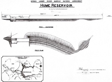
This set of photos is from a leather bound album bearing the inscription "HUME RESERVOIR AUSTRALIA" plus 'The Rt. Hon. L. C. M. S. Amery, P. C., M .P.' all inscribed in gold. It was presented to The Rt. Hon. L. C. M. S. Amery, P. C., M. P, Secretary of State for Dominion Affairs on the occasion of his visit to the Hume Reservoir on 2nd November 1927. This album is of local and national significance as it documents the planning and development of the Hume Reservoir up to 1927. It was the largest water reservoir in the British Empire. The album records the pioneering engineering work that went into its construction.1. Locality Plan and Plan of Dam. The dam is about ten miles by road upstream from Albury and about three-quarters of a mile below the confluence of the Mitta Mitta River and the Murray River. Its main features consist of a concrete portion across the bed of the river with earth embankment at both ends. The foundations throughout are on hard granite, found at an average depth of about 40 feet below the surface, the centre line being located to take advantage of the most favourable rock levels.Heading on page "WORKS UNDER RIVER MURRAY WATERS AGREEMENT/HUME RESERVOIR" Beneath top diagram "FIG. 1. ELEVATION" Beneath second diagram "FIG. 2. PLAN" On map "LOCALITY PLAN"hume reservoir australia, river murray waters scheme, hume weir diagrams, hume weir location -
 Wodonga & District Historical Society Inc
Album - Hume Reservoir Australia Album - Detail plan and explanation, Department of Public Works, N.S.W, 1927
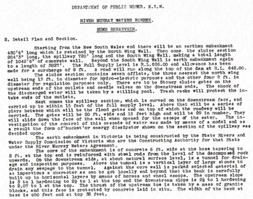
This set of photos is from a leather bound album bearing the inscription "HUME RESERVOIR AUSTRALIA" plus 'The Rt. Hon. L. C. M. S. Amery, P. C., M .P.' all inscribed in gold. It was presented to The Rt. Hon. L. C. M. S. Amery, P. C., M. P, Secretary of State for Dominion Affairs on the occasion of his visit to the Hume Reservoir on 2nd November 1927. This album is of local and national significance as it documents the planning and development of the Hume Reservoir up to 1927. It was the largest water reservoir in the British Empire. The album records the pioneering engineering work that went into its construction.2. Detail Plan and Section. Starting from the New South Wales and there will be an earthen embankment 430 feet 6 inches long which is retained by the North Wing Wall. Then come the sluice section 284 feet 3 inches long, the spillway 720 feet long and the South Wing Wall, making a total length of 1,042 feet 6 inches of concrete wall. Beyond the South Wing Wall is earth embankment again to a length of 3,827 feet. The Full Supply Level is R.L.626.00 and allowance has been made for a surcharge of 9 feet. A road will run along the top of the dam at R.L.642.00. The sluice section contains seven offlets, the three nearest the north wing wall being 13 feet in diameter for hydro-electric purposes and the other four 9 feet in diameter for regulation purposes only. There are to be stony sluice gates on the upstream ends of the outlets and needle valves on the downstream ends. The shock of the discharged water will be taken by a stilling pool. Trash racks will protect the intake ends of the outlets. Next comes the spillway section, which is curved on the downstream face, and carried up to within 15 feet of the full supply level. Above that will be a series of piers between which will be the flood gates and on top of which the roadway will be carried. The gates will be 20 feet wide and 15 feet high and will be 29 in number. They will slide down the face of the wall when opened for the escape of the water. The investigation of the control of this cascade of water was made by means of a model and as a result the form of “bucket” or energy dissipater shown on the section of the spillway was decided upon. The earth embankment in Victoria is being constructed by the State Rivers and Water Supply Commission of Victoria who are the Constructing Authority for that State under the River Murray Waters Agreement. The core of the embankment is of concrete 6 feet wide at the base tapering to 2 feet at the top end and is reinforced with steel rods from the level of the decomposed rock upwards. On the downstream side, at about natural surface level, is a tunnel for drainage and inspection purposes. Above the tunnel is a vertical layer of large stones to drain any seepage to the tunnel. Against the core wall is packed selected material of as impervious a character as can be got locally and beyond that the bank is carefully built up in horizontal layers by means of horses and wheel scoops. The upstream slope is 3-to-1 hardening to 2½-to-1 at the top and the downstream slope is 2½-to-1 hardening to 2.07-to-1 at the top. The thrust of the upstream toe is taken by a mass of granite blocks, and this face is protected by concrete laid in situ. The width of the bank at base is 650 feet and at top 32 feet.hume reservoir australia, river murray waters scheme, hume weir diagrams, hume plan details -
 Wodonga & District Historical Society Inc
Album - Hume Reservoir Australia Album - View from the Victorian bank of the Murray River, May 1923
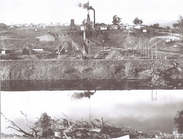
This set of photos is from a leather bound album bearing the inscription "HUME RESERVOIR AUSTRALIA" plus 'The Rt. Hon. L. C. M. S. Amery, P. C., M .P.' all inscribed in gold. It was presented to The Rt. Hon. L. C. M. S. Amery, P. C., M. P, Secretary of State for Dominion Affairs on the occasion of his visit to the Hume Reservoir on 2nd November 1927. This album is of local and national significance as it documents the planning and development of the Hume Reservoir up to 1927. It was the largest water reservoir in the British Empire. The album records the pioneering engineering work that went into its construction.DEPARTMENT OF PUBLIC WORKS, N.S.W. RIVER MURRAY WATERS SCHEME. HUME RESERVOIR. 12. View from the Victorian bank of the river showing in the foreground a levee bank along the New South Wales side of the river with connecting wings back to the higher ground, May 1923. The first stage in the construction of the Dam foundations was carried out inside the levee bank which was at a sufficient height to protect from floods the work going on inside. A length of 300 feet of the Dam was left at a low elevation to allow of the river flowing over it in the second stage of the operations and at the ends of the concrete was brought up above flood level. To divert the river, a Coffer Dam was built across the old bed above and below the Dam site and tying into the end of the concrete wall built inside the levee bank. This completely surrounded the remainder of the site of the Dam and south wing wall, including an area of 12½ acres.hume reservoir australia, river murray waters scheme, hume reservoir construction -
 Wodonga & District Historical Society Inc
Album - Hume Reservoir Australia Album - Driving first row of piles for coffer dam across the river, December 1925
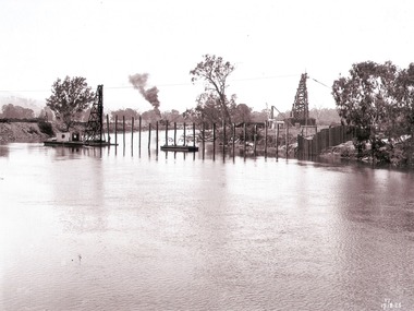
This set of photos is from a leather bound album bearing the inscription "HUME RESERVOIR AUSTRALIA" plus 'The Rt. Hon. L. C. M. S. Amery, P. C., M .P.' all inscribed in gold. It was presented to The Rt. Hon. L. C. M. S. Amery, P. C., M. P, Secretary of State for Dominion Affairs on the occasion of his visit to the Hume Reservoir on 2nd November 1927. This album is of local and national significance as it documents the planning and development of the Hume Reservoir up to 1927. It was the largest water reservoir in the British Empire. The album records the pioneering engineering work that went into its construction.DEPARTMENT OF PUBLIC WORKS, N.S.W. RIVER MURRAY WATERS SCHEME. HUME RESERVOIR. 19. Driving first row of piles for coffer dam across the river. New South Wales. December 1925. Cofferdams are temporary structures used where construction is being carried out in areas submerged in water. They are most commonly used to facilitate the construction or repair of dams, piers and bridges. To divert the river, a Coffer Dam was built across the old bed above and below the Dam site and tying into the end of the concrete wall built inside the levee bank. This completely surrounded the remainder of the site of the Dam and south wing wall, including an area of 12½ acres. hume reservoir australia, river murray waters scheme, hume reservoir construction -
 Wodonga & District Historical Society Inc
Album - Hume Reservoir Australia Album - Excavations for foundations inside coffer dam, January 1927
This set of photos is from a leather bound album bearing the inscription "HUME RESERVOIR AUSTRALIA" plus 'The Rt. Hon. L. C. M. S. Amery, P. C., M .P.' all inscribed in gold. It was presented to The Rt. Hon. L. C. M. S. Amery, P. C., M. P, Secretary of State for Dominion Affairs on the occasion of his visit to the Hume Reservoir on 2nd November 1927. This album is of local and national significance as it documents the planning and development of the Hume Reservoir up to 1927. It was the largest water reservoir in the British Empire. The album records the pioneering engineering work that went into its construction.DEPARTMENT OF PUBLIC WORKS, N.S.W. RIVER MURRAY WATERS SCHEME. HUME RESERVOIR. 21. Excavations for foundations inside coffer dam. New South Wales. January 1927. Cofferdams are temporary structures used where construction is being carried out in areas submerged in water. They are most commonly used to facilitate the construction or repair of dams, piers and bridges. To divert the river, a Coffer Dam was built across the old bed above and below the Dam site and tying into the end of the concrete wall built inside the levee bank. This completely surrounded the remainder of the site of the Dam and south wing wall, including an area of 12½ acres. hume reservoir australia, river murray waters scheme, hume reservoir construction, coffer dam -
 Wodonga & District Historical Society Inc
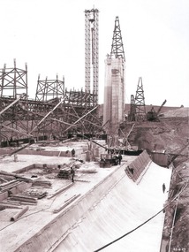
Album - Hume Reservoir Australia Album - Work proceeding inside the coffer dam, August 1927
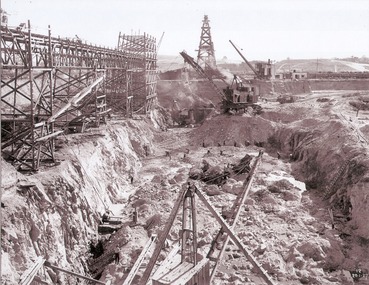
This set of photos is from a leather bound album bearing the inscription "HUME RESERVOIR AUSTRALIA" plus 'The Rt. Hon. L. C. M. S. Amery, P. C., M .P.' all inscribed in gold. It was presented to The Rt. Hon. L. C. M. S. Amery, P. C., M. P, Secretary of State for Dominion Affairs on the occasion of his visit to the Hume Reservoir on 2nd November 1927. This album is of local and national significance as it documents the planning and development of the Hume Reservoir up to 1927. It was the largest water reservoir in the British Empire. The album records the pioneering engineering work that went into its construction.DEPARTMENT OF PUBLIC WORKS, N.S.W. RIVER MURRAY WATERS SCHEME. HUME RESERVOIR. 25. Work proceeding inside the Coffer Dam. This shows the curving downstream face of the Spillway section taking shape, the bottom edge being the line of the contraction joint between the wall and the energy dissipater which has still to be built. Note the steam navvy at the end of the bit of curved work ready to take out the foundations for the energy dissipater. The tall concrete pillar is a portion of the work at the intersection of the main and south wing walls which was built in advance of the rest of the work to accommodate the tail tower of the cableway. The Tail Tower for the first stages of the work stood on the ground. Part of it is seen erected on the pillar while part of it is still in its original position. To command the concreting of the pillar end of the south wing wall a twin hoist tower of steel construction was erected at the end of the belt conveyor. This hoist is 160 feet high. The belt conveyor will at a later stage be raised for the concreting of the upper portion of the dam and the trestles are now being built up for that purpose. A drag line excavator with a 2 cubic yard capacity bucket is at work near the tail tower on the foundations for the south wing wall. New South Wales, August 1927.hume reservoir australia, river murray waters scheme, hume reservoir construction -
 Wodonga & District Historical Society Inc
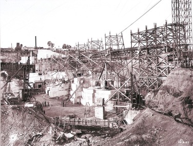
Album - Hume Reservoir Australia Album - Work proceeding inside the coffer dam (2), August 1927
This set of photos is from a leather bound album bearing the inscription "HUME RESERVOIR AUSTRALIA" plus 'The Rt. Hon. L. C. M. S. Amery, P. C., M .P.' all inscribed in gold. It was presented to The Rt. Hon. L. C. M. S. Amery, P. C., M. P, Secretary of State for Dominion Affairs on the occasion of his visit to the Hume Reservoir on 2nd November 1927. This album is of local and national significance as it documents the planning and development of the Hume Reservoir up to 1927. It was the largest water reservoir in the British Empire. The album records the pioneering engineering work that went into its construction.DEPARTMENT OF PUBLIC WORKS, N.S.W. RIVER MURRAY WATERS SCHEME. HUME RESERVOIR. 26. Work proceeding inside the coffer dam. This view was taken from the edge of the cut for the South Wing Wall foundations looking from the opposite direction to that of the preceding photograph, the curving downstream face of the main wall being seen beyond the steam navvy. This view shows the way in which the concrete paddocks are stepped and broken jointed vertically and horizontally. In the distance is the North Wing Wall and Power House stack beyond it. New South Wales, August 1927.hume reservoir australia, river murray waters scheme, hume reservoir construction -
 Wodonga & District Historical Society Inc
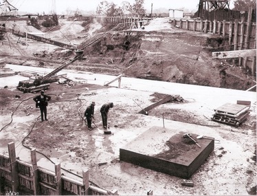
Album - Hume Reservoir Australia Album - Preparing a paddock for concrete. August 1927
This set of photos is from a leather bound album bearing the inscription "HUME RESERVOIR AUSTRALIA" plus 'The Rt. Hon. L. C. M. S. Amery, P. C., M .P.' all inscribed in gold. It was presented to The Rt. Hon. L. C. M. S. Amery, P. C., M. P, Secretary of State for Dominion Affairs on the occasion of his visit to the Hume Reservoir on 2nd November 1927. This album is of local and national significance as it documents the planning and development of the Hume Reservoir up to 1927. It was the largest water reservoir in the British Empire. The album records the pioneering engineering work that went into its construction.DEPARTMENT OF PUBLIC WORKS, N.S.W. RIVER MURRAY WATERS SCHEME. HUME RESERVOIR. 27. Preparing a Paddock for Concrete. Great care is taken in cleaning the surface of the concrete before placing the next layer. A hose applies a jet of water with a pressure of about 150 pounds to remove laitance and all dirt, which is swept off with brooms. (Laitance is the weak, milky or powdery layer of cement dust, lime and sand fines that appear on the surface of concrete. ) The square block of concrete in the foreground is poured at the same time as the concrete surrounding it and acts as a key for the next layer. Usually large granite “plums” or displacers weighing from 2 tons to 8 tons are used for this purpose and are placed in position by the cableway, but while the cableway is out of action the other method has been adopted. In this view may also be seen some of the timber piles and sheeting which form the inner side of the coffer dam. The outer side is formed of steel sheet piling. The space between the two lines of piles is 20 feet wide and is filled with earth after the steel and timber lines have been bound together by steel tie rods. New South Wales, August 1927.hume reservoir australia, river murray waters scheme, hume reservoir construction -
 Wodonga & District Historical Society Inc
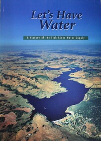
Book - Let's Have Water - A history of the Fish River Water Supply, Robin McLachlan, Denis Barrett, Jack Domis, Nick Welling, 1997
A history of the development of the management of the Fish River Water Supply Scheme in Central NSW. The scheme extends across the local government areas of the Shire of Oberon, the City of Lithgow and the City of the Blue Mountains.non-fictionA history of the development of the management of the Fish River Water Supply Scheme in Central NSW. The scheme extends across the local government areas of the Shire of Oberon, the City of Lithgow and the City of the Blue Mountains.water nsw, fish river region nsw, oberon dam, water resources development nsw australia -
 Eltham District Historical Society Inc
Photograph, Queenstown - St. Andrews District. "Quartz awaiting crushing at the State Battery in Smith's Gully.", c.1929
"The State Battery was the central component in the gold mining of this area from the 1920s. The battery crushed the gold bearing quartz extracted from the mines and was a sizeable weatherboard building enclosing the engine and stampers. All that now remains are the bases for the machinery that comprised the battery, one timber and a couple of concrete bases and the nearby dam, which supplied water. However the historic significance of the site remains and is enhanced by the Queenstown Cemetery on the other side of Smiths Gully Road". - Bick Study 1922 This site is now the Peter Franke Reserve and is managed by Parks Victoria Photo Source: The Leader, Nov. 2nd, 1929This photo forms part of a collection of photographs gathered by the Shire of Eltham for their centenary project book,"Pioneers and Painters: 100 years of the Shire of Eltham" by Alan Marshall (1971). The collection of over 500 images is held in partnership between Eltham District Historical Society and Yarra Plenty Regional Library (Eltham Library) and is now formally known as the 'The Shire of Eltham Pioneers Photograph Collection.' It is significant in being the first community sourced collection representing the places and people of the Shire's first one hundred years.Digital imagesepp, shire of eltham pioneers photograph collection, queenstown, st andrews, gold mining, smiths gully