Showing 776 items
matching specifications
-
 Bendigo Historical Society Inc.
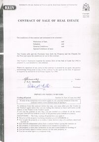
Document - PETER ELLIS COLLECTION: CONTRACT OF SALE
Copy of Contract of Sale of Real Estate and associated papers for property located in Flora Lane, Flora Hill which was purchased by Peter Ellis on 26 May 1993. Contract is in booklet with other loose papers. Contract includes General Conditions, Particulars of Sale, Special Conditions, Guarantee, Vendors Statement to the Purchaser, Shire of Strathfieldsaye Land Information Certificate, Planning Certificate Request for Building Approval Particulars, Coliban Region Water Authority Information Statement, Property Inquiry Application Form, Request for Property Information from Vic roads, Advice on Mine Subsidence Hazard (Department of Energy & Minerals), Map, Copy of Certificate of Title and Folder Numbers. Loose pages include Building Control Act 1981 Inspection Notice, two plans of building, Three plans (Coliban Water Asset Location) of Flora Lane where property is situated, 2 dated 13/11/2007 (have New Carport drawn beside house) and 1 dated 22/11/2007. Last page has specifications for car port.bendigo, house, peter ellis oam, peter ellis collection, reiv, law institute of victoria, real estate institute of victoria ltd, e j gannaway, peter n ellis, ray white bendigo pty ltd, e m monotti & son, rogers and every, craig watts, shire of strathfieldsaye, coliban region water authority, sec, g & fc of vic, telecom, vicroads, bruce l phillips, k deps?, department of energy and minerals, robert james sanderson, t flanagan, land titles office victoria, harston partridge & co pty ltd -
 Orbost & District Historical Society
maps, early 1900s
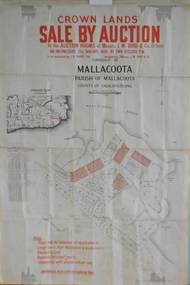
796.1 - Crown Land Sale by auction in the township of Mallacoota on Wednesday January 1920 at 2pm. 796.2 - Snowy River farms , 630 acres of river flat land at Orbost on Wednesday April 28, 1909 at 2.30pm. 796.3 - Famous Orbost Flats - "Important Sale of Snowy River Land" , 900 acres subdivided into 13 choice farms on Wednesday 1st December 1920 at 2.30pm. 796.4 - "Second Great Sale in James' Subdivision", adjoining town of Orbost on 16th May, 1919 at 2pm. 796.5 - "Subdivisional Sale Brooklands Estate", 5 rich Snowy River farms on Wednesday 23rd February at 2.30 at Orbost on account of James Hossack Esq. 796.6 - "Subdivisional sale of Splendid Residence Sites and Handy Small Paddocks" adjoining the progressive town of Orbost on 5th March 1915 at 11am at the rooms of H.James & Co. 796.7 - This is a contract drawing on waxed paper. Crossing near Harbecks Cunninghame Signed and traced N. Anderson 17/11/00. 796.8 - A plan and specification on waxed paper. Shire of Orbost Cunninghame Road - signed by the shire engineer. 796.9 - This is a hand drawn map of Orbost Cunninghame Road, November 1896. 796.10 - This is a hand drawn cross-section of a culvert on the Orbost Cunninghame Road. 796.11 - This is a plan of a culvert on Tabbara Road, 13th January 1899 796.12 - This is a poster for an "Important Subdivisional Sale' for land near Orbost Bridge, on Wednesday 16th March 1921 at the rooms of H. James & Co. These documents are an important part of Orbost history in that they show how the town and surrounding areas were subdivided for farming and residential settlement.A set of twelve maps, plans and land sale posters .orbost-land-1900s maps posters h.james -
 Flagstaff Hill Maritime Museum and Village
Equipment - Foghorn, 20th century
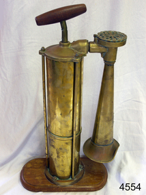
A marine foghorn gives an audible navigational signal to warn vessels of dangers, hazards and the presence of other vessels in fog conditions. The foghorn signal is a series of long and short sounds with short or long pauses between them. These common signals conform to a code called the International Regulations for Preventing Collisions at Sea and provide such information as whether the vessel is under sail or motor, large or small, aground or at anchor. The designs of foghorns vary but they all use a column of air to make a loud sound. Some use vibrating plates or metal reeds, others force air through holes in a revolving cylinder or disc, sounding like a siren, and some use a clockwork mechanism to open the valves that let the air into the horn. They are usually built to meet particular specifications e.g. U.S.C.G. (US Coast Guard). This Tyfon plunger foghorn has a horizontal handle attached to a vertical rod that moves up and down inside a cylinder. When the handle is plunged down, in a similar way to a bicycle pump, the air is forced out of the bottom of the cylinder into a pipe with a bell-shaped horn on the end, making a loud, low sound. The wider base of the cylinder helps to keep it stable. The original type Tyfon foghorns were manufactured in about 1910 by Kochums Mechanical Workshop (Kockums Mechanical Werkstad, Ltd.), Malmo, Sweden. The company was established in 1840, became a Limited company in 1866, and established a shipyard at the Port of Malmo, Sweden, in 1870. The civilian ship production in Malmo ceased in 1987. As well as building ships the company built large industrial and agricultural machinery and maritime goods.this replica foghorn represents the design of a Swedish, Tyfon model 1910. It is an example of the type of safety equipment used on marine vessels to signal other vessels and signal to land. Replica foghorn; portable marine, plunger operation. It has a brass cylinder and adjustable brass horn. The plunger handle and base are wooden. Inscriptions are on the plaque on the horn and moulded into the air intake. Facsimile of a Kockums of Malmo, Sweden, Tyfon model 1910 Fog Horn.Impressed into the attached plaque "KOCKUMS MLK. VERKSTAD / MALMO SWEDEN" and "TRADE TYFON MARK" Also added to the plaque individually "288938" Molded around the circumference of the air intake "TYFON PATENT"flagstaff hill, warrnambool, shipwrecked coast, flagstaff hill maritime museum, maritime museum, shipwreck coast, flagstaff hill maritime village, great ocean road, foghorn, fog horn, tyfon foghorn, kockums mlk verkstad, malmo sweden, replica, warning signal, safety equipment, ship's equipment -
 Eltham District Historical Society Inc
Album - Photograph, J.A. McDonald, Dixons Creek Road, June 1957
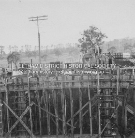
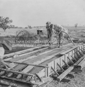
Bridge over Dixons Creek Job 56FD330 June 1957 Formwork for Dixons Creek pier completed Advertising (1957, January 19). The Argus (Melbourne, Vic. : 1848 - 1957), p. 33 (Col. 9). Retrieved August 24, 2022, from http://nla.gov.au/nla.news-article71777065 SHIRE OF ELTHAM. Loan No. 27.-Notice of Intention to Borrow Sum of £ 15,000 for Permanent Works and Undertakings. - Notice is hereby given, that the Council of the Shire of Eltham proposes to borrow the sum of £15,000 on the credit of the municipal revenues of the president, councillors, and ratepayers for the said shire, such sum to be raised by the Issue of debentures in accordance with the provisions of the Local Government Acts. 1. Maximum rate of interest that may be paid is £5/10/ per cent, per annum. 2. The purposes for which the loan is to be applied are: Construction of Sanitary Conveniences at Shire Office, Council's contribution towards costs of Dixons Creek Bridge, Construction of Mt. Pleasant rd., Construction of Cherry Tree rd. 3. The period of the loan shall be 10 years. 4. Moneys borrowed will be repayable by providing out of the Municipal Fund twenty half-yearly instalments of approximately £985/1/6 each, including principal and interest on the first day of October and the first day of April during the currency of the loan. The first Instalment shall be payable on the first day of October 1957. 5. Such moneys shall be repayable at the Commercial Bank of Australia Limited, Melbourne, or at the Council's bankers for the time being in Melbourne. The plans and specifications and the estimates of the costs of the proposed works and a statement showing the proposed expenditure of the moneys to be borrowed are open for inspection at the Shire Office, Eltham. R. J. HAM. Shire Secretary.Record of various Shire of Eltham infrastructure works undertaken during the period of 1952-1962 involving bridge and road reconstruction projects, sometimes with Eltham Shire Council Project Reference numbers quoted. It was during this period that a number of significant improvements were made to roads and new bridges constructed within the shire that remain in place as of present day (2022). In many situations, the photos provide a tangible visible record of infrastructure that existed throughout the early days of the Shire. The album was put together by or under the direction of the Shire Engineer, J.A. McDonald.infrastructure, road construction, shire of eltham, bridge construction, dixons creek bridge, dixon's creek road, 1957-06 -
 Eltham District Historical Society Inc
Album - Photograph, J.A. McDonald, Dixons Creek Road, June 1957
Piles being cast 1957 P. Morris on vibrator Advertising (1957, January 19). The Argus (Melbourne, Vic. : 1848 - 1957), p. 33 (Col. 9). Retrieved August 24, 2022, from http://nla.gov.au/nla.news-article71777065 SHIRE OF ELTHAM. Loan No. 27.-Notice of Intention to Borrow Sum of £ 15,000 for Permanent Works and Undertakings. - Notice is hereby given, that the Council of the Shire of Eltham proposes to borrow the sum of £15,000 on the credit of the municipal revenues of the president, councillors, and ratepayers for the said shire, such sum to be raised by the Issue of debentures in accordance with the provisions of the Local Government Acts. 1. Maximum rate of interest that may be paid is £5/10/ per cent, per annum. 2. The purposes for which the loan is to be applied are: Construction of Sanitary Conveniences at Shire Office, Council's contribution towards costs of Dixons Creek Bridge, Construction of Mt. Pleasant rd., Construction of Cherry Tree rd. 3. The period of the loan shall be 10 years. 4. Moneys borrowed will be repayable by providing out of the Municipal Fund twenty half-yearly instalments of approximately £985/1/6 each, including principal and interest on the first day of October and the first day of April during the currency of the loan. The first Instalment shall be payable on the first day of October 1957. 5. Such moneys shall be repayable at the Commercial Bank of Australia Limited, Melbourne, or at the Council's bankers for the time being in Melbourne. The plans and specifications and the estimates of the costs of the proposed works and a statement showing the proposed expenditure of the moneys to be borrowed are open for inspection at the Shire Office, Eltham. R. J. HAM. Shire Secretary.Record of various Shire of Eltham infrastructure works undertaken during the period of 1952-1962 involving bridge and road reconstruction projects, sometimes with Eltham Shire Council Project Reference numbers quoted. It was during this period that a number of significant improvements were made to roads and new bridges constructed within the shire that remain in place as of present day (2022). In many situations, the photos provide a tangible visible record of infrastructure that existed throughout the early days of the Shire. The album was put together by or under the direction of the Shire Engineer, J.A. McDonald.infrastructure, road construction, shire of eltham, bridge construction, dixons creek bridge, dixon's creek road, 1957-06, p. morris -
 Eltham District Historical Society Inc
Album - Photograph, J.A. McDonald, Dixons Creek Road, June 1957
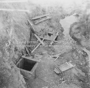
Dixons Creek Road P. Morris – Contractor Dixons Creek (North) abutment 1957 Advertising (1957, January 19). The Argus (Melbourne, Vic. : 1848 - 1957), p. 33 (Col. 9). Retrieved August 24, 2022, from http://nla.gov.au/nla.news-article71777065 SHIRE OF ELTHAM. Loan No. 27.-Notice of Intention to Borrow Sum of £ 15,000 for Permanent Works and Undertakings. - Notice is hereby given, that the Council of the Shire of Eltham proposes to borrow the sum of £15,000 on the credit of the municipal revenues of the president, councillors, and ratepayers for the said shire, such sum to be raised by the Issue of debentures in accordance with the provisions of the Local Government Acts. 1. Maximum rate of interest that may be paid is £5/10/ per cent, per annum. 2. The purposes for which the loan is to be applied are: Construction of Sanitary Conveniences at Shire Office, Council's contribution towards costs of Dixons Creek Bridge, Construction of Mt. Pleasant rd., Construction of Cherry Tree rd. 3. The period of the loan shall be 10 years. 4. Moneys borrowed will be repayable by providing out of the Municipal Fund twenty half-yearly instalments of approximately £985/1/6 each, including principal and interest on the first day of October and the first day of April during the currency of the loan. The first Instalment shall be payable on the first day of October 1957. 5. Such moneys shall be repayable at the Commercial Bank of Australia Limited, Melbourne, or at the Council's bankers for the time being in Melbourne. The plans and specifications and the estimates of the costs of the proposed works and a statement showing the proposed expenditure of the moneys to be borrowed are open for inspection at the Shire Office, Eltham. R. J. HAM. Shire Secretary.Record of various Shire of Eltham infrastructure works undertaken during the period of 1952-1962 involving bridge and road reconstruction projects, sometimes with Eltham Shire Council Project Reference numbers quoted. It was during this period that a number of significant improvements were made to roads and new bridges constructed within the shire that remain in place as of present day (2022). In many situations, the photos provide a tangible visible record of infrastructure that existed throughout the early days of the Shire. The album was put together by or under the direction of the Shire Engineer, J.A. McDonald.infrastructure, road construction, shire of eltham, bridge construction, dixons creek bridge, dixon's creek road, 1957-06 -
 Eltham District Historical Society Inc
Album - Photograph, J.A. McDonald, Dixons Creek Road, June 1957
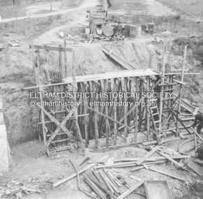
Dixons Creek Road Bridge over Dixons Creek – 56FD330 June 1957 Dixons Creek pier forming columns and beam Advertising (1957, January 19). The Argus (Melbourne, Vic. : 1848 - 1957), p. 33 (Col. 9). Retrieved August 24, 2022, from http://nla.gov.au/nla.news-article71777065 SHIRE OF ELTHAM. Loan No. 27.-Notice of Intention to Borrow Sum of £ 15,000 for Permanent Works and Undertakings. - Notice is hereby given, that the Council of the Shire of Eltham proposes to borrow the sum of £15,000 on the credit of the municipal revenues of the president, councillors, and ratepayers for the said shire, such sum to be raised by the Issue of debentures in accordance with the provisions of the Local Government Acts. 1. Maximum rate of interest that may be paid is £5/10/ per cent, per annum. 2. The purposes for which the loan is to be applied are: Construction of Sanitary Conveniences at Shire Office, Council's contribution towards costs of Dixons Creek Bridge, Construction of Mt. Pleasant rd., Construction of Cherry Tree rd. 3. The period of the loan shall be 10 years. 4. Moneys borrowed will be repayable by providing out of the Municipal Fund twenty half-yearly instalments of approximately £985/1/6 each, including principal and interest on the first day of October and the first day of April during the currency of the loan. The first Instalment shall be payable on the first day of October 1957. 5. Such moneys shall be repayable at the Commercial Bank of Australia Limited, Melbourne, or at the Council's bankers for the time being in Melbourne. The plans and specifications and the estimates of the costs of the proposed works and a statement showing the proposed expenditure of the moneys to be borrowed are open for inspection at the Shire Office, Eltham. R. J. HAM. Shire Secretary.Record of various Shire of Eltham infrastructure works undertaken during the period of 1952-1962 involving bridge and road reconstruction projects, sometimes with Eltham Shire Council Project Reference numbers quoted. It was during this period that a number of significant improvements were made to roads and new bridges constructed within the shire that remain in place as of present day (2022). In many situations, the photos provide a tangible visible record of infrastructure that existed throughout the early days of the Shire. The album was put together by or under the direction of the Shire Engineer, J.A. McDonald.infrastructure, road construction, shire of eltham, bridge construction, dixons creek bridge, dixon's creek road, 1957-06 -
 Bendigo Military Museum
Photograph - Photographic Technicians performing tasks at the Army Headquarters Survey Regiment, c1960s
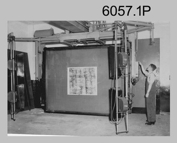
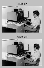
These eight photographs were most likely taken in the 1960s in Lithographic Squadron at the Army Headquarters Survey Regiment, Fortuna, Bendigo. Although Photo .1P is not annotated the remainder have the name of the technicians written on the back. The equipment operated by the technicians is the KLIMCH Commodore camera. The main tasks undertaken by the technicians were most likely enlargements and reductions of map reproduction material. The KLIMSCH Commodore camera was introduced in 1953 and was the largest in the Southern Hemisphere. It was replaced with a new model of the same size in 1979. The new model with its computer-based interface provided productivity gains with improved speed and its consistent results led to less wastage in time and materials. Its variomat lens system provided improved retention of map feature linear weights during the camera reduction process. The typed description pasted on the back of photo .5P states “Cpl R. MacKenzie of Bentley, Perth (WA) of the AHQ Survey Regt, located at “Fortuna”, Bendigo, (Vic). Has been in the Army for 5 years. He removes the lens cap from the 70 inch F16 lens of the giant KLIMSCH camera used in map making for the Army. The camera which was specially made for the Army in Germany is fully automatic and power operated. It is claimed to be one of the biggest automatic cameras of its type in the world. It was made to the specifications of the Aust Army Survey Corps to assist in the production of the very high standard maps for the Army. The AHQ Survey Regt also assists Commonwealth and other Govt departments in the printing of maps required other than for Army needs. The KLIMSCH camera is used for cartographic mapping photography.” This is a set of photographs of technicians operating photographic reproduction equipment at the Army Headquarters Survey Regiment, Bendigo c1960s. The photographs were printed on photographic paper and are part of the Army Survey Regiment’s Collection. The photographs were scanned at 300 dpi. .1) - Photo, black & white, c1960s, Les ‘Snow’ Taylor, Lithographic Squadron .2) - Photo, black & white, c1960s, Les ‘Snow’ Taylor, Lithographic Squadron .3) - Photo, black & white, c1960s, John Rolfe, Lithographic Squadron .4) - Photo, black & white, c1960s, John Rolfe, Lithographic Squadron .5) - Photo, black & white, c1960s, CPL R. MacKenzie, Lithographic Squadron .6) - Photo, black & white, c1960s, unidentified, Lithographic Squadron .7) - Photo, black & white, c1960s, George Graham, Lithographic Squadron .8) - Photo, black & white, c1960s, L to R: Bill Snelson, George Graham, Lithographic Squadron.1P – no annotation .2 to .4 – personnel names (less rank) annotated on back. .5 – name and rank annotated on back, with detailed typed description .6 to .8 – personnel names (less rank) annotated on back. royal australian survey corps, rasvy, army survey regiment, army svy regt, fortuna, asr, litho -
 Federation University Historical Collection
Document - Document - Design, E J Barker: University of Melbourne: Bachelor of Mechanical Engineering; Engineering Design Part II, 1946
... specifications ...Four folders containing an Engineering Design Part II Project. Each has detailed written information and drawings. No.1: To design an Extruder Addition to the hydraulic press in the plate shop to enable it to be used as an extruding press to operate on materials similar in behaviour to a wax. No. 2: To design a flywheel of uniform strength of not less than 25 feet. No 3: To design cams, valve gear and inlet and exhaust valves for a 6 cylinder truck engine. No 4: To design an experimental brown coal autoclave for drying brown coal in 10 kilogram lots. Jack chose to do Engineering while still at Footscray Technical School as it gave access to Diploma Courses and tertiary studies. This enabled him to enter the University of Melbourne and do a Bachelor in Mechanical Engineering - 1945, 1946, and 1947. In 1948 he did a Diploma in Education at Melbourne University. From this path he was able to follow a career in teaching and his first appointment was at the School of Mines in Ballarat, (SMB) 1949. He became the first Vice Principal of SMB in 1960 and then Principal in 1964 to 1976. From 1976 to his retirement in 1987, he was the Foundation Director of Ballarat College of Advanced Education (BCAE). The Library building at Mount Helen Campus is named after him.Four manila folders with design assessment in each. Each folder has written descriptions and detailed drawings.e j barker, jack barker, melbourne university, engineering, diploma of mechanical engineering, diploma of electrical engineering, school of mines ballarat, smb, diploma in education, vice principal, principal, foundation director, ballarat college of advanced education, bcae, bachelor of mechanical engineering, library, mount helen campus, engineering drawing, design, specifications, manufacture, extruder addition, hydraulic press, flywheel, cams, valve gear, inlet valve, exhaust valve, 6 cylinder truck engine, autoclave, brown coal -
Federation University Historical Collection
Document - Document - Design, E J Barker: University of Melbourne: Bachelor of Mechanical Engineering; Class notes and definitions
... specifications ...Notes are definitions and information on various aspects of Mechanical Engineering - Heat Engines, Internal Combustion Engines, Symbols for Physical Quantities, Historical-people and their inventions, Minutes of Meeting of Instructors and Examiners, Engineering Thermodynamics III, Refrigeration. Jack chose to do Engineering while still at Footscray Technical School as it gave access to Diploma Courses and tertiary studies. This enabled him to enter the University of Melbourne and do a Bachelor in Mechanical Engineering - 1945, 1946, and 1947. In 1948 he did a Diploma in Education at Melbourne University. From this path he was able to follow a career in teaching and his first appointment was at the School of Mines in Ballarat, (SMB) 1949. He became the first Vice Principal of SMB in 1960 and then Principal in 1964 to 1976. From 1976 to his retirement in 1987, he was the Foundation Director of Ballarat College of Advanced Education (BCAE). The Library building at Mount Helen Campus is named after him.Handwritten and typed notes. Plain and lined sheets.e j barker, jack barker, melbourne university, engineering, diploma of mechanical engineering, diploma of electrical engineering, school of mines ballarat, smb, diploma in education, vice principal, principal, foundation director, ballarat college of advanced education, bcae, bachelor of mechanical engineering, library, mount helen campus, engineering drawing, design, specifications, manufacture, heat engines, internal combustion engine, symbols of physical quantities, hisory, people, inventions, instructors, examiners, report, refrigeration -
 Melbourne Tram Museum
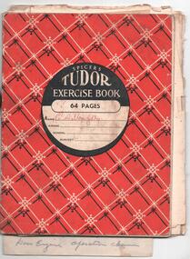
Document - Notebook, Charlie Willoughby, personal notes on tramcar maintenance, operations, recovery etc of C. Willoughby, late 1950's to early 1960's
Exercise book with personal notes on tramcar maintenance, operations, recovery etc of C. Willoughby in a Spicers Tudor Exercise book - 64 pages with arithmetical tables on the rear cover. Topics covered: Rail Grinder - details on how to operate and maintain it North Fitzroy Dick Kerr, Clyde, K35 and RC2 Controller sequences and diagrams - notes on testing and faults Buzzer wiring diagrams Maintenance of trams interiors and rooves - items to be checked for Line Breakers Lighting Circuits Compressors Trolley poles etc Air operated doors Re-railing of Maximum Traction trams - 22E ditto for equal wheel bogies ditto when split points Use of false trucks Derailments on the Royal Park line Electrical equipment faults Adjusting Trolley Poles heights and tension Notes on truck types and braking Brake diagram summary, giving specifications and a list of relevant drawings Forms for the insulation testing of the Rail Grinders Checking motor leads and electrical equipment - written on the rear of a St Patrick's Day Procession notice for 1962. Advice from Neil Elfick, 23/6/2018 knew him when the Running Shed Foreman at Kew Depot.trams, tramways, tramcars, faults, controllers, 22e trucks, derailments, accidents, royal park, grinder, notices and information, st patricks day -
 Trafalgar Holden Museum
Vehicle - VN Commodore, 1988
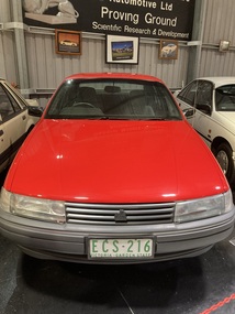
The VN Commodore was available in Executive, S, SS, Berlina and Calais specification levels, although a more basic SL model (opt. code A9K) was supposedly offered to government and fleet buyers, as it was not officially listed as part of the Commodore range. Changes in the relative values of the Australian dollar, the Japanese yen, and the US dollar made it impractical to continue with the well-regarded Nissan engine of the VL. Instead, Holden manufactured their own 90-degree V6 based on an old Buick design from the US, although initially it was imported. The 5.0-litre V8 remained optional and received a power boost to 165 kW (221 hp). Both these engines used multi point GM EFI and the V6 using 3 coil-packs for ignition. Holden and HSV developed this car as the basis for racing in Group A Confederation of Australian Motor Sport events. While the minimum number of cars built to qualify in Australian Touring car Championships, with modified body kit, brakes or engine is 500, only 302 VN were built but CAMS granted an exemption allowing them to compete.Holden and HSV had worked hard to develop this car to be a serious competitor to the Skyline, Ford Sierra and the BMW which had dominated in the previous years. This was to be the Holden’s answer and coincided with the return of Peter Brock back to the Holden team from 1987.Mechanically the cars were fitted with reworked version of Holden’s 4.9 litre V8. The engine block was cast for additional strength, modified cylinder heads roller rockers and high fuel flow fuel injection was applied. Output was 215 kw at 5200revs and, though at today’s standard, that is not that much it was very impressive at that time. The drive was through a six speed ZF gearbox with a heavy duty racing clutch and a limited slip differential.Under the Hawke government's Button car plan, which saw a reduction in the number of models manufactured locally, and the introduction of model sharing, the VN Commodore was rebadged as the Toyota Lexcen, named after the late America's Cup yacht designer, Ben Lexcen. Subsequently, the Toyota Corolla and Camry were, similarly, badged as the Holden Nova and Holden Apollo.Red executive 4 door sedanHolden Lion and stone emblem grille centre, Commodore boot LHS, Lion and stone emblem boot RHS.vehicle, vn commodore, holden, car -
 Melbourne Tram Museum
Letter - Correspondence, Melbourne & Metropolitan Tramways Board (MMTB), "Trolley Buses", 1922-36
File containing correspondence between the MMTB Chief Engineer Mr. Strickland and various companies, including Railless Ltd, Australian General Electric, English Electric / Dick Kerr and its UK consultants Heap and Digby (H&D) between the period August 1922 and August 1936. Includes drawings, technical specifications, some of which are duplicated in the Reg Item 535 file. For a listing of the contents of this file and of Reg Item 535, see Related Documents - htd535-536list.pdf Item 536 - Trolley Buses Listed from top of file, in order found. Letters generally to/from MMTB Chief Engineer. Date Type Notes 7/8/1936 Letter from TE Barnes – re Bremen Germany Steam Omnibus. Three pages. On foolscap paper – rest quarto. Has been damaged. 3/2/1926 Letter from Bruce Henderson re transport in the Glen Eira Rd area – poor private bus. 25/10/1925 Letter to G. Higgins, regarding a paper he had presented and printed in Australian Municipal Journal about transport around Melbourne, predicted the demise of trams, trains. Notes Spencer St bridge. Copy of paper is pinned with letters. 28/819/22 Copy of letter to H&D from AEC (see above) Includes the Mexborough test gradient drawing. Undated Pamphlet from Railless Limited about Birmingham’s new trolley buses. 16/3/1923 Extract from Electric Railway and Tramway Journal – wages of trolleybus drivers not getting paid extra in Bradford. Two copies pinned together. 9/4/1923 Letter from H&D re pamphlet exchange You should have had it! 23/2/1923 Letter to H&D asking for information. Has a note re the Board’s attitude towards motor buses. 28/8/1922 to 24/23 Series of letters pinned together with L. de Koenneritz regard trolley buses and Paris. Noted that the MMTB did not have the legislative power to run trolley buses. 15/2/1922 to 10/4/23 Series of letters pinned together with the Aust. GE regarding trolley buses and references to their operation in journals. 10/1/1923 Letter from H&D re request for information on driving gear of Railless Ltd. vehicles 23/2/1923 Letter to H&D re above. 23/2/1923 Sheet of paper on “Steads Review” paper – pamphlet not yet to hand. 8/11/1922 to 10/1/1923 Series of letters with H&D pinned together asking for Railless driving gear – reluctant to provide. 26/9/1922 Letter from H&D, with copy of letter from English Electric enclosing materials regarding Trolley Bus equipment. Note much of this material is the same as that in Reg Item 535 contained within the green cloth tape. Performance curves for DK 26B motor Blueprint – 4449 – outline of controller DK, Type D, form B. Specification for DK 26B trolley motor. Blueprint – drawing 2810 – DK 26 Motor Blueprint – No. 1312D – controller diagram Pamphlet – EE – tramcar Type D automatic circuit Breakers. Publication No. 230, dated 9/1920. Ditto, Form A, drawings No 3565, 1/1/19. Performance curves for DK85A motor Blueprint – P2002M034 – DK85 Motor. EE specification for Traction Motor DK85 Modified from a tram motor. Blueprint – EE drawing – P2002M036 – DK85 motor with ball bearings. EE blueprint P2102F021, traction control wiring for form D controller. EE blueprint P2103F033 – outline of controller type SE1, form C and D. EE blueprint P2102Z011 – wiring diagram for type SE1 form controller. EE blueprint – P2102F025 – diagram of connections (wiring) for Type SE1, form D controller.trams, tramways, trolley buses, melbourne, mmtb, aec, heap and digby, english electric, railless, dick kerr, general electric -
 Bendigo Military Museum
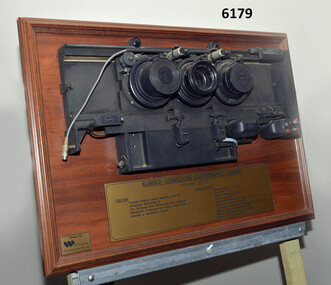
Plaque - Mounted Klimsch Commodore Cartographic Camera Lenses, WYCOMBE Constructions Pty Ltd, 1997
These are the Lenses from the Klimsch Commodore Cartographic Camera that was located in Lithographic Squadron at the Army Survey Regiment, Fortuna, Bendigo. The KLIMSCH Commodore camera was originally introduced to the Survey Regiment in 1953 and was the largest in the Southern Hemisphere. It was replaced with a new model of the same size in 1977. These lenses are from this new model. The new model with its computer-based interface provided productivity gains with improved speed and its consistent results led to less wastage in time and materials. Its variomat lens system provided improved retention of map feature linear weights during the camera reduction process. The camera which was specially made for the Australian Army in Germany was fully automatic and power operated. It was claimed to be one of the biggest automatic cameras of its type in the world. It was made to the specifications of the Royal Australian Army Survey Corps to assist in the production of the very high standard maps for the Australian Army. THIS KLIMSCH COMMODORE CARTOGRAPHIC CAMERA was in operation 1977 - 1997". It was a Precision Darkroom Camera especially suited for Cartographic Reproduction of Line, Continous Tone, Halftone and Colour Separation. Reproduction of Negatives and Positives from a variety of Reflection or Transmission Originals. Its characteristics were: Maximum Negative Size 1.27m sq, Copy Holder (Vacuum) 2m sq, Maximum Enlargement 400%, Maximum Reduction 13%, Automatic 60, 90 and 120cm Focal Length Lens, Transmission or Reflection Originals, Pulsed Xenon, Photo Flood or Fluorescent Tube Light Source, Maximum Reflection Original 1.3m x 1.85m, Maximum Transmission Original 1.3m x 1.85m, Exposure Light Monitoring System." The camera was superseded by computerized image manipulation software associated with the Automap system. These significant and extremely high-quality Lenses were retrieved by WYCOMBE Constructions Pty Ltd during the demolishment of the camera in 1997 and then mounted on a display board. See also Item 6189.4P for more photographs of the camera.Lenses from the Klimsch Commodore Cartographic Camera mounted on a very heavy timber display board. The display board contains an engraved plate that describes the technical characteristics of the camera."KLIMSCH COMMODORE CARTOGRAPHIC CAMERA 1977 - 1997", "FUNCTION: Precision Darkroom Camera especially suited for Cartographic Reproduction of Line, Continous Tone, Halftone and Colour Separation. Reproduction of Negatives and Positives from a variety of Reflection or Transmission Originals." "CHARACTERISTICS: Maximum Neg Size 1.27m sq, Copy Holder 2m sq, Maximum Enlargement 400%, Maximum Reduction 13%, Automatic 60, 90, 120cm Focal Length Lens, Transmission or Reflection Originals, Pulsed Xenon, Photo Flood or Fluorescent Tube Light Source, Maximum Reflection Original 1.3m x 1.85m, Maximum Transmission Original 1.3m x 1.85m, Exposure Light Monitoring System." royal australian survey corps, rasvy, fortuna, army survey regiment, army svy regt, asr, litho -
 Wodonga & District Historical Society Inc
Photograph - Codling Collection 01 - Woodland Grove, Wodonga
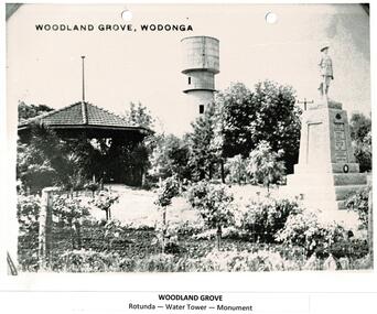
Miss Olive Codling was a Foundation Member and a Life Member of the Wodonga Historical Society. Many of her prize-winning photos are held in the Society Collection. She also held a range of roles and committee positions in a wide range of Wodonga community organisations. These included the Horticultural Society, the Wodonga Arts Council, the Wodonga Camera Club and the Wodonga Lapidary Club. Woodland Grove is located in the triangular reserve at the corner of High and Hovell Streets, Wodonga. ‘Woodland Grove". It was named in honour of John Woodland at the same time as the opening of the band rotunda in September 1920. John Woodland, Wodonga Shire’s first president, was born in Kent, England, in 1829 and came to Sydney with his parents in 1839. He arrived in the Wodonga district about 1853, where he created a successful carrier's business. He first lived on the Old Barnawartha Estate and a few years later purchased land at Green Hills, Wodonga West, where he farmed and also ran a hotel. The hotel licence was relinquished to give attention to duties as secretary and clerk of works to Wodonga Shire, which was then the Wodonga Riding of the Shire of Yackandandah. He was a main agitator for the separation of Wodonga district from Yackandandah Shire. This was successful in 1876, and he became the first president of Wodonga Shire. He held this post for two years, then taking on the role of shire secretary in 1878 until 1913. He concurrently undertook the role of clerk of works (engineer) from 1896 to 1907. As clerk of works he prepared the plans and specifications for, and supervised the construction of the big bridges on the Albury road and at Bonegilla and other important works. In his mid 70s, he proffered his resignation on a number of occasions but it was not accepted. Despite physical weakness and impaired vision, John continued his duties to the end, with the help of his daughter Rose Murphy. Rose became shire secretary for 20 years after her father’s death in 1913.This photo collection is significant as it documents the naming of a public area in Wodonga to honour an original and long-serving member of the Wodonga Shire Council.A black and white photo of Woodland Grove in High Street, Wodonga. It includes the rotunda, the water tower and the soldier's memorial. There is a post and wire fence in the foreground as well as several trees and rose bushes. Beneath the photo: "WOODLAND GROVE / Rotunda - Water Tower - Memorial"high st wodonga, woodland grove, john woodland -
 Melbourne Tram Museum
Legal record, Melbourne & Metropolitan Tramways Board (MMTB), "Agreement Melbourne and Metropolitan Tramways Board with A.N. Colquhoun", May. 1948
Bound Document, two large ruled grey folded sheets with containing various schedules and letters typed onto foolscap (folio) or quarto sheets. Titled "Agreement Melbourne and Metropolitan Tramways Board with A.N. Colquhoun "signed and sealed on 18th May 1945. Bound on left hand side with green ribbon. Gave Archibald Norman Colquhoun the right to advertising on the inside of tramcars and buses and on the rear of tickets for five years. Gave details of the contract, minimum payments, rebates and conditions of the contract. Schedule A - two pages - space available in tramcars Schedule B - two pages - buses ditto Schedule C - passenger check tickets / annum - some 350million - one page Schedule D - actual tendered document, 15/4/1948 - one page Schedule E - the Specification for the tender - five pages Schedule F - Letter signed by A.N. Colquhoun, on The Reilly Advertising Co. letterhead of which has was the Managing Director giving his credentials. Schedule G - supporting letter on The Reilly Advertising Co letterhead. Schedule H - Letter from the Commercial Bank of Australia Ltd - supporting Mr A.N. Colquhoun. Schedule I - letter from MMTB advising A.N. Colquhoun of his successful bid. Schedule J - Draft agreement in tender document - five pages - signed 15/4/1948."996/7" in top left hand corner of document and stamped "Treasurer"trams, tramways, tickets, advertisements, tramcars, buses, contracts, legal agreements -
 Bendigo Military Museum
Map - Map Extract - Charterhouse of Mendip, John James Raisbeck, Unknown
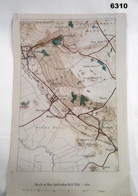
Map extract showing the towns of Cheddar, Rodney Stoke, Westbury and a smaller town of Easton. The area depicted is part of Somerset, England. Map is hand drawn by J.J. Raisbeck date unknown. John James RAISBECK was born on 4 July 1880 at Christchurch New Zealand. He served 4 years (Citizen Military Force - CMF) in 9th Australian Light Horse Regiment in Central VIC with the rank 2nd Lieutenant. He was the first Australian appointed to the Survey Section RAE, on 16 April 1910, as a draughtsman which was his civilian profession, with the rank Warrant Officer, honorary 2nd Lieutenant. He was required to resign his commission in the CMF. He supervised the draughting work of the Section in Melbourne and was largely responsible for the mapping standards and specifications set in the production of the Cowes one-inch-to-one-mile military map, which became the enduring Australian standard. He was also responsible for supervising the printing of the maps by the Victorian Government Printer. He was appointed 2nd Lieutenant in the AIF Survey Corps draft on 6 December 1917 (from Melbourne) embarking for England on 22 December 17. He was attached to the Australian Corps Topographic Section in France from 21 April 1918 to 5 March 1919 serving as Second-in-Command and as Officer Commanding. He was promoted Lieutenant 15 October 1918, attending the AIF Survey School, Southampton in 1919, returning to Australia 23 June 1919, before his AIF appointment was terminated 17 July 1919. He went on to serve the Survey Section RAE and Australian Survey Corps, including in the Second World War, having been promoted Captain then Major and Officer Commanding Army Headquarters Cartographic Section until February 1940. He retired after 33 years of service to military survey, and after serving the Corps in two world wars, on 4 July 1943 with the retired rank Lieutenant-Colonel. He was the author of the article ‘A Short History of the Military Survey of Australia, 1907-1936’, published in The Australian Surveyor, Sept 1, 1937Map extract slightly larger than A4. Scale: One Inch to One and a half Mile. 1:31680, 9 x copiesSignature of "J.J. Raisbeck" bottom right-hand cornerroyal australian survey corps, rasvy, fortuna, army survey regiment, army svy regt, asr -
 Bendigo Military Museum
Photograph - Detachment - Army Survey Regiment, Bonegilla, Victoria, c1973
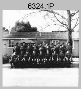
This is a set of three photographs of personnel from the Detachment - Army Survey Regiment taken in front of its main map production building at Bonegilla, Victoria in c1973. This cartographic map production sub-unit of the Army Survey Regiment operated in buildings owned by the School of Military Survey from 17th of June 1970 to the 30th of September 1985. A total of 800 topographic maps ranging in scale from 1:25,000 to 1: 250,000 scale were completed. A major focus of production in the 1970s was the cartographic completion of the Papua-New Guinea 1:100,000 map series and the Flexiflow quality control system was developed as a tool to coordinate production. The Flexiflow system comprised a series of job plans and charts linked to a task allocation to resource magnetic planning board. Using critical path analysis and task prioritisation, complex job planning was efficiently scheduled, and re-prioritisations readily made. Reproduction requirements were effectively coordinated by way of weekly courier to the Army Survey Regiment at Bendigo. Supervisors and technicians fully embraced the system as they could understand their role, others around them and the positive production achievements. WO1 Bill Boyd (who does not appear in this photograph) was the technical warrant officer for 11 years at the Detachment was awarded the OAM, the Order of Australia Medal for leading the development and the implementation of the Flexiflow system. By mid-1982, production of maps at these scales was undertaken digitally on Bendigo’s AUTOMAP 2 system and the Detachment reverted to production of small-scale large format RAAF aeronautical charts. Detachment personnel managed to produce 18 charts in the following two years, which was an impressive achievement for the staff, given major differences in format, specification and scales. Development of digital production of aeronautical charts in 1984-85 led to gradual reduction in production output and contracting out production was instigated to meet the shortfall and as a consequence the Detachment closed in September 1985. See pages 177 to 180 of Valerie Lovejoy’s book 'Mapmakers of Fortuna – A history of the Army Survey Regiment’ ISBN: 0-646-42120-4. for more information on the history of the Detachment at Bonegilla.This is a set of three photographs of the Detachment - Army Survey Regiment taken in front of the main map production building at Bonegilla, Victoria in c1973. The photographs were printed on photographic paper and are part of the Army Survey Regiment’s Collection. The photographic proofs were scanned at 600 dpi. .1) to .3) - Photo, black & white c1973. Back Row L to R: Peter Simpson, Chris Edwards, unidentified (x2), Colin Harden, Rowan Gillies, Bob Rowley OAM, Steve Hansen, Stu Thaxter. Centre Row L to R: Kevin Boehm, Dennis McCarthy, Peter Cross, unidentified, Brian Ryan, unidentified, Ian Marner, unidentified, Phil Smalley. Front Row L to R: Geoff Haynes, Bruce Wetzig, Dave Thompson, unidentified, OC Bob Roche, Ike Lever, John McCulloch, Dick Barwald, unidentified. There are no personnel annotated.royal australian survey corps, rasvy, army survey regiment, detachment - army survey regiment, army svy regt, asr -
 Flagstaff Hill Maritime Museum and Village
Equipment - Dentist Drill, Late 19th century
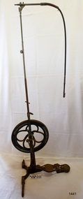
The design of this and other similar treadle powered dental engine (or dentist drill) was in common use by dentists from the 1870’s into the 1920's. When electricity became accessible to most communities the electrically powered dental engines began to take over from the treadle power. Over the ages teeth were extracted using picks and scissors and other gouging instruments. Bow drills, hand drills and even a "bur thimble" drill were later used to prepare cavities for filling. Some drills were made bendable by attaching flexible shanks between the metal bur and the handle, giving access to the teeth at the back of the mouth. Other mechanical devices were introduced along the way, such as clockwork drills, but they were hard to handle and inefficient. Over the centuries “dentistry has been performed by priests, monks and other healers. This was followed by barbers; the barber’s chair may well have been the precursor to the dental chair. “(SA Medical Heritage Society Inc.) In 1871 James Morrison patented the first commercially manufactured 'foot treadle dental engine', the first practica dental engine although others had been introduced as early as 1790 (by John Greenwood). Handmade steel burs or drills were introduced for dental handpieces, taking advantage of the significant increase in the speed of the drill. In 1891 the first machine-made steel burs were in use. The treadle drill reduced the time to prepare a cavity from hours to less than ten minutes. In 1876 the Samuel S. White Catalogue of Dentist Instruments listed a 12 ½ inch wheel diameter dental engine, with 14 bright steel parts, for sale at US $55 In today’s market, this is the equivalent to US $1200 approx. The specifications of that dental engine are very similar to the this one in our Flagstaff Hill Maritime Village’s collection. It is interesting to note that workings of a similar treadle dentist drill were used and modified to power a treadle spinning wheel of one of the volunteer spinners at Flagstaff Hill Maritime Village. The foot treadle dental engine was a milestone in dental history. “Historic importance of treadle powered machines; they made use of human power in an optimal way” (Lowtech Magazine “Short history of early pedal powered machines”) The invention of a machine to speed up the process of excavation of a tooth lead to the invention of new burs and drills for the handpieces, improving speed and the surgical process of dentistry. They were the fore-runner of today’s electrically powered dental engines. This treadle-powered dentist drill, or dentist engine, is made of iron and steel and provides power for a mechanical dental hand-piece that would be fitted with a dental tool. The drill has a three footed cast iron base, one foot being longer than the other two. A vertical C shaped frame is joined into the centre of the base, holding an axle that has a driving-wheel (or flywheel) and connecting to a crank. A slender, shoulder height post, made from telescoping pipes, joins into the top of this frame and is height adjusted by a hand tightened screw with a round knob. On the post just above the frame is a short metal, horizontal bar (to hold the hand-piece when it is not in use). A narrow tubular arm is attached to the top of the stand at a right angle and can move up and down. At the end of the arm is a firmly fixed, flexible rubber hose protected for a short distance by a sheath of thin metal. At the end of the hose there is a fitting where the drill’s hand-piece would be attached; a small, silver coloured alligator clip is also at the end. A treadle, or foot pedal, is hinged to the heel to the long foot of the base, and joined at the toe to the crank that turns the driving-wheel. There is a spring under the toe of the treadle. The metal driving-wheel has a wide rim. Touching the inside of the rim are four tubular rings that bulge towards the outside of the driving-wheel, away from the pole, and all meet at the hub of the axle. The axle is bulbous between the inside of the driving-wheel and the frame then passes through the frame and is attached on the other side. The driving-wheel has a groove around which a belt would sit. The belt would also fit around a pulley on the arm, at the top of the post. The pulley is joined to a rod inside the arm and this spins the drill's hand-piece and dental tool holder. The two shorter feet of the base are made from a long metal bar that has been curved outwards, and its centre is bolted to the base of the pole. Under the ends of the curved legs of the base are wedge shaped feet. The driving-wheel is decorated in light coloured paint on both sides, each side having three sets of floral decals evenly spaced around them, and each about a sixth of the wheel's circumference. Similar decoration is along the sides of the frame. The foot pedal has decorative cutout patterns in the centre of the foot and at the toe. On the long foot of the stand is some lettering with a fine, light coloured border around it. The lettering is hard to read, being a dark colour and flaking off. There are also remnants of fine, light coloured flourishes. The foot pedal has lettering of the maker’s trade mark cast into the metal at the ball of the foot. Lettering on the base is peeling and difficult to read. The foot pedal has a trade mark cast into it that looks like a combination of ‘C’ , ‘S’ , ‘A’, ‘R’. flagstaff hill, warrnambool, shipwrecked coast, flagstaff hill maritime museum, maritime museum, shipwreck coast, flagstaff hill maritime village, great ocean road, dentist, teeth, dental drill, dental engine, treadle drill, foot powered drill, treadle engine, orthodontics, dental surgery, james morrison -
 Flagstaff Hill Maritime Museum and Village
Equipment - Dentist Drill, Late 19th century
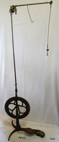
The design of this and other similar treadle powered dental engine (or dentist drill) was in common use by dentists from the 1870’s into the 1920's. When electricity became accessible to most communities the electrically powered dental engines began to take over from the treadle power. Over the ages teeth were extracted using picks and scissors and other gouging instruments. Bow drills, hand drills and even a "bur thimble" drill were later used to prepare cavities for filling. Some drills were made bendable by attaching flexible shanks between the metal bur and the handle, giving access to the teeth at the back of the mouth. Other mechanical devices were introduced along the way, such as clockwork drills, but they were hard to handle and inefficient. Over the centuries “dentistry has been performed by priests, monks and other healers. This was followed by barbers; the barber’s chair may well have been the precursor to the dental chair. “(SA Medical Heritage Society Inc.) In 1871 James Morrison patented the first commercially manufactured 'foot treadle dental engine', the first practica dental engine although others had been introduced as early as 1790 (by John Greenwood). Handmade steel burs or drills were introduced for dental handpieces, taking advantage of the significant increase in the speed of the drill. In 1891 the first machine-made steel burs were in use. The treadle drill reduced the time to prepare a cavity from hours to less than ten minutes. In 1876 the Samuel S. White Catalogue of Dentist Instruments listed a 12 ½ inch wheel diameter dental engine, with 14 bright steel parts, for sale at US $55 In today’s market, this is the equivalent to US $1200 approx. The specifications of that dental engine are very similar to the this one in our Flagstaff Hill Maritime Village’s collection. It is interesting to note that workings of a similar treadle dentist drill were used and modified to power a treadle spinning wheel of one of the volunteer spinners at Flagstaff Hill Maritime Village. The foot treadle dental engine was a milestone in dental history. “Historic importance of treadle powered machines; they made use of human power in an optimal way” (Lowtech Magazine “Short history of early pedal powered machines”) The invention of a machine to speed up the process of excavation of a tooth lead to the invention of new burs and drills for the handpieces, improving speed and the surgical process of dentistry. They were the fore-runner of today’s electrically powered dental engines. This treadle-powered dentist drill, or dentist engine, is made of iron and steel and provides power for a mechanical dental handpiece that would be fitted with a dental tool. On the foot is painted lettering naming it "The Brentfield" and there is a fine line of light coloured paint creating a border around the name. The paint under the lettering is peeling off. The drill has a Y-shaped, three footed cast iron base, one foot being longer than the other two. A vertical frame is joined into the centre of the base, holding an axle that has a driving-wheel (or flywheel) and connecting to a crank. A slender, shoulder height post, made from adjustable telescoping pipes, joins into the top of this frame. On the post just above the frame is a short metal, horizontal bar (to hold the hand-piece when it is not in use). A narrow tubular arm is attached to the top of the stand at a right angle and can move up, down and around. There is a pulley each side of the joint of the arm and a short way along the arm is fitted a short metal pipe. A little further along the arm a frayed-ended cord hangs down from a hole. At the end of the arm is another pulley and a joint from which hangs a long, thin metal pipe with two pulleys and a fitting on the end. A treadle, or foot pedal, is joined to the long foot of the base, and joined at the toe to the crank that turns the driving-wheel. The metal driving-wheel has a wide rim. Touching the inside of the rim are four tubular rings that bulge towards the outside of the driving-wheel, away from the pole, and all meet at the hub of the axle. The axle fits between the inside of the driving-wheel and the frame then passes through the frame and is attached on the other side. The driving-wheel has a groove around which a belt would sit. The belt would also fit around a pulley on the arm, at the top of the post. The pulley is joined to a rod inside the arm and this spins the drill's hand-piece and dental tool holder. The foot pedal has a cross-hatch pattern on the heel and the ball of the foot has tread lines across it. The end of the toe and the instep areas have cut-out pattern in them. "The ____/ Brentfield / __ DE IN L___" (Made in London) painted on the long foot of the base. Marked on the drill connection is “Richter De Trey, Germany”flagstaff hill, warrnambool, shipwrecked coast, flagstaff hill maritime museum, maritime museum, shipwreck coast, flagstaff hill maritime village, great ocean road, dentist, teeth, dental drill, dental engine, treadle drill, foot powered drill, treadle engine, orthodontics, dental surgery, james morrison, the brentfield, richter de trey, german dental fitting, london dental drill -
 Working Heritage Crown Land Collection
Award - Royal Mint Building Award, JA Dodd Excellence in Construction
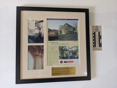
2002 Excellence in Construction AwardsFramed Award 2002 Excellence in Construction Awards, JA Dodd LTD, Excellence in Construction, (Existing Buildings) Under $2 million, Project: The Royal Mint Building, Architect: Robert Peck von Hartel Trethowan, Location: 280 William Street Melbourne, J A Dodd Ltd's refurbishment of the historic former Royal Mint Building delivered to the client's specification in retaining the features of this historic building, while at the same time providing modern office accommodation with state of the art facilities. New works have been defined by a modern style encompassing glass, stainless steel and flush surfaces, offering a stark departure from the ornate finishes of the original building. Traditional timber mouldings, tiles stonework and intricate paint methods have been used only where repairs to the existing building were required. The judges praised the superb job and made special mention of the exposed roof trusses. 38 master builder awards -
 Ballarat Tramway Museum
Book, City of Ballaarat, "Mayors Special Report Ballarat Tramways", Sep. 1971
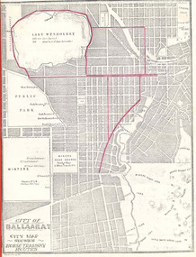
Historically significant for at the time it demonstrated aspects of the evolution of Ballarat Tramways and yields information about the formation of the tramways, the Councils viewpoint and has a strong association with the Mayor of the time.Twenty two page book, produced by photocopying, side stapled and bound with a red plastic binding, titled "Mayor's Special Report Ballarat Tramways", dated 20 September 1971 for presentation to the City of Ballaarat Council Meeting 27 Sept. 1971 and signed by the Mayor, J.A.Chisholm. Note pages 18 and 19 have been reversed. Comprises: Page 1 - map (image 1829i1) - of Ballarat (Ballaarat) showing the horse tram routes in red (appear to have been drawn in with a red pencil). Note the Sebastopol route terminates at Rubicon St. Page 3 - letter to the City Councillors from the Mayor Page 4 - Outline of the "The Ballarat Tramway System" Pages 5 - 7 - Conditions for tendering the horse tram system within the City of Ballarat" Pages 8 - 11 - Specifications and Agreement for the Ballaarat Tramways (horse trams). pages 12 - 19 - Memorandum of Agreement with the British Insulated Wire Company (later ESCo) Page 20 - Copy of letter from the Secretary of the SEC to the Minister of Fuel and Power, dated 10 Sept. 1971 advising of the formal abandonment of the Ballarat and Bendigo tramway systems. Page 21 - five photos (image 1829i3) of trams in Ballarat, including the bogie tram decorated for the Queens visit, courtesy of Mr. L. J. Denmead, Tramways Superintendent. Page 22 - Plan (image 1829i2) of Ballarat Bus Services, showing route numbers, destinations and existing tramway routes. 3rd copy added 16/7/2010trams, tramways, city of ballaarat, mayor's reports, ballaarat tramway company, british insulated wire company, esco, bus services, sec -
 Parks Victoria - Cape Nelson Lightstation
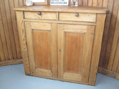
Furniture - Cabinet
The cabinet has a curved back and would have been custom‐built to fit the dimensions of the lantern room interior. It is likely to date from when the lighthouse was built in 1884 and may have been among the items delivered by the government steamer dispatch early in March which included ‘the lantern and other fittings for the Cape Nelson Lighthouse’. The Public Works Department provided a range of lightstation furnishings including office desks and cabinets, and domestic settings for keepers’ quarters, with nineteenth century items often stamped with a crown motif and the PWD monogram however the curved cupboards installed in Victoria’s lighthouse lantern rooms do not appear to display this small feature. Further research may reveal more about their manufacture and it is tempting to think that they were perhaps even supplied by Chance Bros as part of the entire lantern room installation. The company usually provided the timber battens for the lantern room paneling, and a cabinet may have been included in the assemblage. Another possibility is that the specially designed cabinet was made on site by carpenters along with other fittings. It is not known whether it is attached to the wall or movable; if attached it is considered to be a fixture and included in the Victorian Heritage Register listing for the lightstation (VHR H1773). Its location, when identified in the CMP of April 1995, was on the ‘lower lantern level’, where there was also a ‘timber step ladder’ (Argus, 6 March 1884, p6. nineteenth or early twentieth century), ‘timber framed lighthouse specification’, ‘timber framed chart’ and telephone .Residue on the furnishing indicates that it was formerly painted green, the colour of some of the other fixtures in the room, such as the original cast iron ladder. It is now partially varnished and the corner to the top’s edging on the right side has been cut off. The lighthouse also has a large curved back, two‐door cupboard. Other similar cabinets with curved backs survive at Cape Schanck, varnished wood cabinet with brass door knob, no drawers; Point Hicks, painted green with silver doors, no drawers and Gabo Island, bench top, 2‐door, no drawers, green paint removed to reveal cedar timber). Cape Nelson’s curved cabinet is unique among these examples for having drawers. The cabinet is a unique, original feature of the lantern room and has first level contributory significance for its historic values and provenance.The bench top cupboard has two drawers, each above a door, and each door is framed and beveled around a central panel. The cabinet has a curved back. -
 City of Moorabbin Historical Society (Operating the Box Cottage Museum)
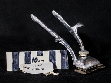
Barbers' Equipment, hair clippers 'BURMAN", c1950
Hair clippers are specialized implements used to cut human head hair. They work on the same principle as scissors, but are distinct from scissors and razors. :Hair clippers comprise a pair of sharpened comb-like blades in close contact one above the other which slide sideways relative to each other, a mechanism which may be manual or electrical to make the blades oscillate from side to side, and a handle. The clipper is moved so that hair is positioned between the teeth of the comb, and cut with a scissor action when one blade slides sideways relative to the other. Friction between the blades needs to be as low as possible, which is attained by choice of material and finish, and frequent lubrication. Hair clippers are operated by a pair of handles that are alternately squeezed together and released. Barbers used them to cut hair close and fast. The hair was picked up in locks and the head was rapidly depilated. Mid 20thC such haircuts became popular among boys, and young men in the military and in prisons. Burman & Sons Ltd, of Ryland Road, Birmingham, West Midlands, manufactured Burman-Douglas steering gear. Their recirculating worm and ball design of steering gear was fitted to pre-war vehicles such as the Ford Eight and the Ford Prefect, the Bedford CA, plus heavy trucks and off-road vehicles - both pre and post-war. In its day, Burman-Douglas steering-gear was regarded as.... a "quality" feature of a car chassis specification, but the worm and ball design was eventually surpassed by the cheaper rack and pinion design that dominates today. The company also manufactured motorcycle gearboxes, horse clippers and barbers’ clippers. 1871 Company founded. 1897 Private company. 1930s Gearbox for Ariel Square-four motorcycle. (Exhibit at Birmingham Thinktank museum) 1933 Burman and Sons Limited, manufacturers of horse and barbers' clippers, sheep shearers, motor cycle gear boxes and steering gears, Ryland road, Edgebaston 1953 S. F. Burman, M.B.E., Managing Director, Burman and Sons, Ltd 1955 Acquired by Vono Industrial Products. 1961 Manufacturers of motor and motorcycle accessories. 1,500 employees. 1968 Supplied rack and pinion steering units to Ford 1978 Adwest Group acquired Burman and Sons, the steering gear part of Duport. 1986 Major reduction in staffing at Burman due to fall in demand for its products and delivery problems. A set of hand held barbers’ hair clippers with an adjustable screw, from Burman and Sons Ltd of Birmingham, England. Chrome plated, in good condition, c1950. On left arm ; BURMAN On right arm ; MADE IN ENGLANDbarbers, hairdressing, hair clippers, grooming, horse clippers, cars, motor cycles, gear boxes, rack and pinion , worm and ball, steering gears, steel manufacture, birmingham england, burman and sons ltd, moorabbin, bentleigh, ormond, cheltenham, market gardeners, -
 Bendigo Military Museum
photograph - Cartographic Squadron Production – Army Survey Regiment, Fortuna, c1980
This collection of 12 photos was most likely taken in 1980. The photos were most likely taken in Cartographic Squadron’s Ante Room, the Attic and small offices on the top floor of Fortuna Villa. The computer based Editwriter typesetting system was introduced in 1975 as a replacement to the aging Fotosetter machine. It was operated by a specialised technician, who generated a large variety of map type styles and sizes quickly and reliably, as well as text panels. CPL Richards performed this task for several years and in photo .1P and .2P is reading off a type order next to the computer monitor. Output on Copy proof adhesive backed stripping type film replaced messy wax and spray adhesives in 1978. The Editwriter capability supported all RASvy units and contractor type setting requirements. Scribing was the cartographic process of drafting features such as drainage, relief, vegetation, roads and culture on specially coated map reproduction material. The cartographic technician scribed out the map feature such as a contour to a specified line width on the map sheet, using a tool affixed with a sapphire tipped cutter. The quality control edit (Proving) stage of map production was the first opportunity to inspect a proof of the map independently and systematically. Proving tasks were carried out by technicians conversant of the map product specification and task requirement, however, was not involved in its production. Corrections were identified, marked up and sent to back to the correcting section or contractors. Terrain Embossing was a manual map production technique to produce hill shading on medium to small scale graphics and air charts. SPR John Martin is seen in photos .8P to.10P using a fine embossing metal stylus to push down on the drainage impression on a thin malleable opaque plastic material (AK Poligraphy). Ridge lines were then pushed down using the contour impression as a guide, on the opposing side of the AK Poligraphy to create a 3D plastic model terrain effect. The map impression was sprayed with white paint and photographed to create a contone tone hill shade. SPR Gina (Coore) Neilson is seen in photo .11P washing a contone positive of a land mass in a solution. The contone components were registered to the map sheet, as shown in photo .12P and masked using an air brush and a halftone negative was then created. The terrain embossing method of producing hill shading was more efficient to produce than previous specialised artistic methods such pencil/eraser and air brush. Furthermore, a more consistent enhancement of terrain on charts was achieved between technicians.This is a set of 12 photographs of Cartographic Squadron performing four map production tasks at the Army Survey Regiment, Fortuna, Bendigo c1980. The first ten photographs were on 35mm negative film and were scanned at 96 dpi. Photos .11P and .12P were on photographic paper and scanned at 300 dpi. They are part of the Army Survey Regiment’s Collection. .1) - Photo, black & white, c1980, Editwriter typesetter, CPL Paul Richards. .2) - Photo, black & white, c1980, Editwriter typesetter, CPL Paul Richards. .3) - Photo, black & white, c1980, Scribing contours on a RAAF Chart, SPR Megan (McBurney) Reynolds. .4) - Photo, black & white, c1980, Scribing contours on a RAAF Chart, SPR Megan (McBurney) Reynolds. .5) - Photo, black & white, c1980, Scribing contours on a RAAF Chart, SPR Rod Skidmore. .6) - Photo, black & white, c1980, Scribing contours on a RAAF Chart, SPR Rod Skidmore. .7) - Photo, black & white, c1980, Formal quality control edit (Proving), CPL Ian Belmont. .8) - Photo, black & white, c1980, Hill Shade Terrain Embossing, SPR John Martin. .9) - Photo, black & white, c1980, Hill Shade Terrain Embossing, SPR John Martin. .10) - Photo, black & white, c1980, Hill Shade Terrain Embossing, SPR John Martin. .11) - Photo, black & white, c1980, Hill Shade Terrain Embossing, SPR Gina (Coore) Neilson. .12) - Photo, black & white, c1980, Hill Shade Terrain Embossing, unidentified..1P to .10P No personnel are identified. .11P and .12P annotated ‘Terrain Embossing’royal australian survey corps, rasvy, army survey regiment, army svy regt, fortuna, asr, carto -
 Flagstaff Hill Maritime Museum and Village
Functional object - Dry Measurement Container, Late 18th to early 19th century (before the standardised measurement was introduced in England in 1824)
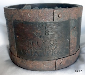
The peck has been in use since the early 14th century when it was introduced as a measure for flour. The term referred to varying quantities until the modern units of measurement were defined in the 19th century. Cities in England used to have official standard weights and measures for that city or area. These containers were marked with the city's name and emblem, merchant’s weights and measures would then be checked against this to make sure they weren't trying to cheat their customers. The item in the collection is a standard measure approved by Bristol City and used by that City’s grocers to measure dry goods such as peas, beans, sugar, flour, meal etc., and its metal banding ensures that the measure cannot be reduced in size to cheat customers. Additional Information: The British Imperial System evolved from the thousands of Roman, Celtic, Anglo-Saxon, and customary local units employed in the middle Ages. Traditional names such as pound, foot, and gallon were widely used, but the values so designated varied with time, place, trade, product specifications, and dozens of other requirements. Early royal standards were established to enforce uniformity took the name Winchester, after the ancient tenth century capital of Britain. King Henry VII reaffirmed the customary Winchester standards for capacity and length and distributed royal standards throughout the realm. This process was repeated about a century later in the reign of Queen Elizabeth I. In the 16th century, the rod (5.5 yards, or 16.5 feet) was defined (once again as a learning device and not as a standard) defined by the length of the left feet of 16 men lined up heel to toe as they emerged from the church. By the 17th century usage and legal statute had established the acre, rod, and furlong at their present values together with other historic units such as the peck. Establishment of the System: The Weights and Measures Act of 1824 and the Act of 1878 established the British Imperial System based on precise definitions of selected existing units. The 1824 act sanctioned a single imperial gallon to replace the wine, ale, and corn (wheat) gallons that were in general use. The new gallon was defined as equal in volume to 10 pounds avoirdupois of distilled water weighed at 62°F with the barometer at 30 inches, or 277.274 cubic inches (later corrected to 277.421 cubic inches). The two new basic standard units were the imperial standard yard and the troy pound, which was later restricted to weighing drugs, precious metals, and jewels. In 1963 an act of parliament abolished archaic measures as the rod and chaldron and a metric system was adopted. An early example of a dry measuring container giving a snapshot of how imperial weights and measures developed in England to evolve the British measurement system into the metric arrangement that most countries have adopted today including Australia. It has social significance as an item that was in everyday use by grocers and other merchants to measure dry goods in the late 18th to early 19th centuries and used specifically in the Bristol region of England as an officially recognised measurement.Wooden measurement container with iron banding and hand made rivets container is a Quarter Peck official measurement container. Inscriptions are impressed into the sides of the wooden body. The container has the official crown and emblem of the City of Bristol, indicating this item was the Bristol City standard quarter peck measurement.Impressed into the timber on the front, a crown emblem over "C B G / CITY OF BRISTOL / QUARTER", on one side "HALF" , another side "PECK". Handwritten in white chalk on the base is "1458"flagstaff hill, warrnambool, shipwrecked-coast, flagstaff-hill-maritime-museum, flagstaff-hill-maritime-village, weights and measures, quarter peck, measurement container, dry grocery measure, bristol city measurement standard, city of bristol, british weights and measures, 18th and 19th centure standard measures -
 Ringwood and District Historical Society
Document - Folder, Land Sale - Monterey Park Subdivision, Warrandyte Road, Ringwood North, Vic. - 1981
Foolscap manilla folder containing double-sided flyer advertising residential subdivision development, including outline of local facilities and services, with locality map and layout of Monterey Park streets. Subdivision includes Parkwood High School, Tortice Drive, Heape Way, Appleberry Place, Stringybark Court, Conifer Court, Crawley Grove, Monterey Close (later Monterey Place), Lucy Place, Middlebrook Drive, Gahnia Close, Glanfield Court, Cone Close, Jull Parade, Pinus Close (later Pinetree Court), Radiata Close, Old Warrandyte Road, and entry from Warrandyte Road. Vendor - Jennings Industries Limited, 690 Springvale Road, Mulgrave, 3170, Phone 5618000. A4 enclosures with tables showing each allotment List Price, Builders Price, Cash Price and Terms Price. Information page headed "Form of Restrictive Covenant to be incorporated in Transfer" specific to Certificates of Title. Restrictive Covenant (summary): (Name/s) "... will not erect or construct or cause to be erected or constructed on the land hereby transferred (a) Any front boundary fence, other than a fence which does not exceed one metre in height unless the same is set back as least 1.5 metres from the front boundary and the same is effectively screened from that boundary by the planting of trees, shrubs or plants. (b) Any side boundary fence other than a fence which is set back at least 1.5 metres from the front boundary on which does not exceed 1 metre in height within 1.5 metres of the front boundary. (c) For a period of 5 years from the date hereof, any building on the said land unless and until the Plans and Specifications thereof have first been approved by the said Residential Developments Pty. Limited. (d) For a period of 2 years from the date hereof whilst the said land remains vacant any Signboard or Notice advertising the sale of the said lot or any other lot. These covenants shall appear on the Certificate of Title to issue for the said land and run with the land." -
 Flagstaff Hill Maritime Museum and Village
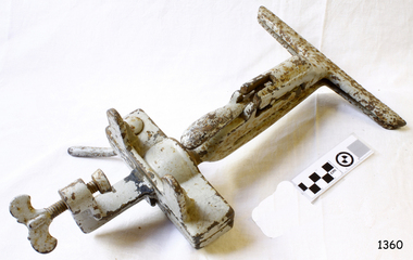
Tool - Bench Saw Vice, Henry Disston & Sons, 1910 -1925
The subject item is a saw blade sharpening clamp that attaches to a bench allowing the operator to sharpen the teeth on a saw with a file while keeping the saw blade in an upright position. Henry Disston (1819–1878) began his career as an American saw maker in Philadelphia. He emigrated from England in 1833 and started making saws and squares in 1840. In 1850, he founded the company that would become the largest saw maker in the world the ”Keystone Saw Works” on the Delaware River. Some five years later, Disston built a furnace possibly the first melting plant for steel in America and began producing the first crucible saw steel ever made in the United States. While his competitors were buying good steel from Britain, he was making his own, to his specification, for his own needs. Disston subsequently constructed a special rolling mill exclusively for saw blades. Over the following decade, the Disston company continued to grow, even while dedicating itself to the Union Army's war effort. In 1865, when his son Hamilton Disston rejoined the business after serving in the Civil War, Disston changed the company's name to Henry Disston & Son. Henry Disston and his sons set the standards for American saw makers, both in terms of producing high-quality saws and developing innovative manufacturing techniques. Disston also started making files in 1865. In September 1872, Henry Disston and two other men dug a part of the foundation for what was to become the largest saw manufacturing facility in the world: Disston Saw Works. This was in the Tacony section of Philadelphia. Having previously moved his expanding business from near Second and Market Streets to Front and Laurel Streets, Disston sought to establish his business away from this cramped area. It took over 25 years to move the entire facility to Tacony. This Philadelphia neighborhood seems to have been the only company town in the United States established within an existing city. At its peak of operations, Disston Saw Works employed 8,000 people and the factory covered 300 acres. The company, known as Henry Disston and Sons, Inc by the early 20th century, cast the first crucible steel in the nation from an electric furnace in 1906. The firm's Armour plate building near Princeton Avenue and Milnor Street contributed tremendously to the World War II effort. But the company's innovation and industriousness would not last forever. In 1955, with mounting cash-flow problems and waning interest on the family's part to run the firm, Henry Disston and Sons were sold to the H.K. Porter Company of Pittsburgh. Porter's Disston Division was sold in 1978 and became the Henry Disston Division of Sandvik Saw of Sweden. This division was then sold in 1984 to R.A.F. Industries of Philadelphia and became known as Disston Precision Incorporated, a maker of specialized flat steel products. In 2013, R.A.F. Industries sold Disston Precision Inc. in a private sale. Although the company has ceased making Disston handsaws, the Disston brand name still exists in this firm. A significant American company that pioneered the making of high-quality steel and saws along with other tools and accessories. The subject item is significant as it was made at a time when the company was in its hay day. Adjustable Ball & Socket Saw Sharpening vice, cast iron, with clamp to attach to a workbench. Made by Henry Disston & Co. No 1 painted greyflagstaff hill, warrnambool, flagstaff-hill, flagstaff-hill-maritime-museum, maritime-museum, shipwreck-coast, flagstaff-hill-maritime-village, saw clamp, henry disston & sons, saw sharpening, tool accessories, wood saws -
 Federation University Historical Collection
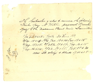
Document, Contract for the Madame Bent Gold Mining Company, 1886, 1886
Handwritten on foolscap paper, with red seal on last page.1) The Subcontractor is also to remove the following [ ? ] from Mr Webb's paddock ... to the Madame Bent Mine Grenville ... .2) Specification for the taking doan, removal and reerection 2 Engines 2 boilers pumping gear, Bob, Poppett heads and Capstone etc, for teh Mdame Bent G.M.Cy Grenville. The company will provide ... .3) Morey's Coys yard, together with holding down bolts, and the following ... .4) to the extent of Bed ... Carpentry Work - To carefully take down the poppet heads and co... and erect the same on the claim complete ... .5) Engine Framing as shown for the winding engines and pumping engines. Properly fitted to get ... .6) The boilers to be fed in front. The contractor to cut and drill all necessary holes in the boilers and pipes - to fire blow ... The contractor to make good any damage or breakage or loss to machinery or any part hereof that may occur to it during the removal of the reerection of same. The loss or damage, if any, not being made good by the contractor, or in the event of the works not being proceeded with to the satisfaction of the Company;s Engineer, The company's Engineer hereby ... .7) of the whole of the works, and in default thereof the COntractor shall forfeit the sum of two pounds ... Signed James Malcolm Witness L. Menz The Common seal of the company was affixed this thirteenth day of December:/86 by its manager James Burrell in the presence of [illegible] managers Seal - Madame Bent Gold Mining Company Durham Lead Buninyongmadame bent gold mining company, richard squire, james malcolm, james burrell -
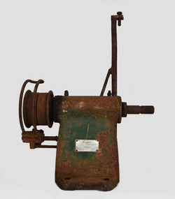 National Wool Museum
Tool - Grinder, 1960-69
Cooper S.E. Ball Bearing Grinder made and guaranteed by Sunbeam Corporation Limited. Grinders like this example have been made the same since the early 1900s, with this grinder thought to have been produced in the 1960s. It is belt driven, with the other end of the belt being attached to an engine; the same engine that would have powered the overhead shearing equipment in shearing sheds. It was common for shearing teams to bring their own equipment, especially pre-1960 as most shearing sheds were not connected to power, and shearers preferred to work with their own equipment. The engines that powered the shears and grinder were typically fuelled with kerosene or petrol. The large circular disks are attached to the bolt that protrudes from the grinder and fastened tightly with a nut. An example of seeing a similar grinder in action can be found on the following link - https://www.youtube.com/watch?v=O7eimI_Gm9o. Inventor Frederick Wolseley made the world's first commercially successful power-shearing system in Australia in 1888. US company Cooper, which had been founded in 1843 as a maker of sheep dip, began selling Wolseley equipment in the USA in 1895. The Chicago Flexible Shaft Company successfully entered the power-shearing market a few years later and entered a joint venture with Cooper. It set up a branch in Sydney and sold shearing sets, and engines to power them, into the Australian market. In 1921 the US parent company, realising it needed to make products whose sales were not as seasonal as those of shearing equipment, made its first household appliances and branded them Sunbeam. In 1933, changes in exchange rates and taxes led the company to manufacture engines and shearing equipment in Australia via subsidiary Cooper Engineering, which changed its name to Sunbeam in 1946. Although most Australians know of this company as a major manufacturer of household appliances, its rural division flourished and retained the Sunbeam name for shearing equipment even after it was taken over by New Zealand company Tru-Test in 2001. The grinder is formed from a central arch shaped block of green painted metal. Much of this paint has been lost to age, leaving the grinder in a ‘farm used’ condition with much surface oxidation present. On the front of the arch is a specification plate, reading “Cooper S.E. ball bearing grinder. Made and guaranteed by Sunbeam”. At the foot of the arch, three bolt holes are found for securing the grinder to the base of a solid wooden surface. Two of the bolt holes are found on the front of the grinder, with another found on the rear. From the central arch, a bolt protrudes to the right of the grinder. This large bolt is for securing a grinding plate to the grinder. Above the central arch is a pendulum which holds the comb / cutter that is being sharpened. From the pendulum, a large arm extends down (not pictured) to meet and strike the plate spinning at a rapid speed. On the left-hand side of the central arch of the grinder, a wheel is found which a belt is attached to for power. This belt is then attached to a separate engine, spinning the wheel and hence powering the grinder. The wheel is partially covered with a section of protective bent tube, designed to provide protection from the rapidly spinning wheel. Below this wheel is the belt shifter. It is designed to move the protective bent tube from one side of the grinder to the other, to accommodate the grinder in the setup of different shearing sheds. The two separate grinding plates are identical. They have a slight slope for sharpening the comb and cutters in the correct method, with a slight bias towards the base, or “tooth”, of the equipment. The disks have a large central bolt for attaching to the grinder. They have tags on the horizontal axis of the grinding plates, for securing the plates in transportation, and to help with initial alignment when setting up the grinder. The reverse of these grinding plates has the same green painted metal finish found on the grinder. This paint is also in a ‘farm used’ condition, with surface oxidation present. The grinder would be provided from the factory with a comb holder, shifter for securing the grinding plates, emery cloth and emery glue. The emery cloth is what does the actual grinding and is applied to the grinding disks, replacing once well worn. These items can be seen in the final images in the multimedia section, showcasing advertising for this grinder. Plate. Inscribed. “Cooper / S.E. BALL BEARING GRINDER / MADE AND GUARANTEED BY / Sunbeam / CORPORATION LIMITED / SYDNEY MELBOURNE / ADELAIDE BRISBANE ”sheep shearing, shearing equipment, sunbeam, grinder